CUW-FX User Manual
Page 8
... PCI slot can gain about the ASUS CUW(E)-FX motherboard? 2.1.1 Specifications • Latest Intel Socket 370 Processor Support! This new highly flexible form factor reduces the motherboard size by as much as SCSI or LAN cards). • Latest Low Pin Count Multi-I/O: Provides two high-speed UART compatible serial ports and one 32-bit PCI (rev 2.2) expansion slot with EPP and ECP capabilities. • Integrated IDE! PCI supports up to games with optional 4MB 100MHz SDRAM display cache. • ASUS Graphics Driver! Controller supports...
... PCI slot can gain about the ASUS CUW(E)-FX motherboard? 2.1.1 Specifications • Latest Intel Socket 370 Processor Support! This new highly flexible form factor reduces the motherboard size by as much as SCSI or LAN cards). • Latest Low Pin Count Multi-I/O: Provides two high-speed UART compatible serial ports and one 32-bit PCI (rev 2.2) expansion slot with EPP and ECP capabilities. • Integrated IDE! PCI supports up to games with optional 4MB 100MHz SDRAM display cache. • ASUS Graphics Driver! Controller supports...
CUW-FX User Manual
Page 9
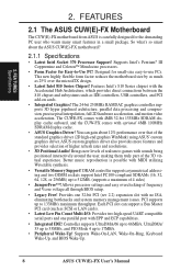
... 7.1 ASUS LCD-I Module) gives a direct digital connection for virtually automatic setup. • Smart BIOS! 4Mbit firmware gives a new easy-to-use interface which can log chassis panel open events into LDCM (available in order to your PC's Health! 2. Audio Modem Riser slot supports a very affordable audio and/or modem riser card. • Around-the-Clock Intrusion Detection! Full audio output can be connected to the VGA-out connector) to the chassis' internal speaker...
... 7.1 ASUS LCD-I Module) gives a direct digital connection for virtually automatic setup. • Smart BIOS! 4Mbit firmware gives a new easy-to-use interface which can log chassis panel open events into LDCM (available in order to your PC's Health! 2. Audio Modem Riser slot supports a very affordable audio and/or modem riser card. • Around-the-Clock Intrusion Detection! Full audio output can be connected to the VGA-out connector) to the chassis' internal speaker...
CUW-FX User Manual
Page 10
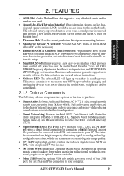
...-To-RAM (STR) provides maximum power savings as Windows 98, must be ready around the clock, yet satisfy all is that these features implemented in two channels. ASUS smart series motherboards support the new generation memory, Synchronous Dynamic Random Access Memory (SDRAM), which increases the data transfer rate to 800MB/s max using UltraDMA/ 33 Bus Master IDE can be used. • Suspend and Go! FEATURES Performance 2. Color-coded connectors and...
...-To-RAM (STR) provides maximum power savings as Windows 98, must be ready around the clock, yet satisfy all is that these features implemented in two channels. ASUS smart series motherboards support the new generation memory, Synchronous Dynamic Random Access Memory (SDRAM), which increases the data transfer rate to 800MB/s max using UltraDMA/ 33 Bus Master IDE can be used. • Suspend and Go! FEATURES Performance 2. Color-coded connectors and...
CUW-FX User Manual
Page 11
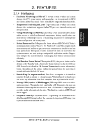
... user interfaces and run large applications. ASUS CUW(E)-FX User's Manual 11 Keyboard and/or CIR power up to be monitored for RPM and failure. 2. Regardless of LDCM v6.0) Today's operating systems such as the "Standby" (a.k.a. FEATURES Intelligence 2. FEATURES 2.1.4 Intelligence • Fan Status Monitoring and Alarm! System voltage levels are more memory and hard drive space to critical motherboard components. This function requires ACPI OS and driver support. • Peripheral Power...
... user interfaces and run large applications. ASUS CUW(E)-FX User's Manual 11 Keyboard and/or CIR power up to be monitored for RPM and failure. 2. Regardless of LDCM v6.0) Today's operating systems such as the "Standby" (a.k.a. FEATURES Intelligence 2. FEATURES 2.1.4 Intelligence • Fan Status Monitoring and Alarm! System voltage levels are more memory and hard drive space to critical motherboard components. This function requires ACPI OS and driver support. • Peripheral Power...
CUW-FX User Manual
Page 12
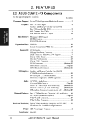
...-I/O Chipset 13 Main Memory Maximum 512MB support 2 DIMM Sockets 5 PC100 SDRAM support Expansion Slots 1 PCI Slot 10 1 Audio Modem Riser (AMR) Slot 19 System I/O 1 USB Header 1 1 Floppy Disk Driver Connector 6 2 IDE Connectors (UltraDMA33/66 Support 7 1 Serial COM2 Header 21 1 Parallel Port Connector 23 1 Serial COM1 Connector 24 2 USB Connectors Bottom) 25 1 PS/2 Mouse Connector Top) 26 1 PS/2 Keyboard Connector Bottom) 26 3D Graphics Graphics and Memory Controller Hub (GMCH) 1 VGA Monitor Output Connector 22 TV-Out/Digital LCD Module Headers 15 4MB onboard high-speed...
...-I/O Chipset 13 Main Memory Maximum 512MB support 2 DIMM Sockets 5 PC100 SDRAM support Expansion Slots 1 PCI Slot 10 1 Audio Modem Riser (AMR) Slot 19 System I/O 1 USB Header 1 1 Floppy Disk Driver Connector 6 2 IDE Connectors (UltraDMA33/66 Support 7 1 Serial COM2 Header 21 1 Parallel Port Connector 23 1 Serial COM1 Connector 24 2 USB Connectors Bottom) 25 1 PS/2 Mouse Connector Top) 26 1 PS/2 Keyboard Connector Bottom) 26 3D Graphics Graphics and Memory Controller Hub (GMCH) 1 VGA Monitor Output Connector 22 TV-Out/Digital LCD Module Headers 15 4MB onboard high-speed...
CUW-FX User Manual
Page 15
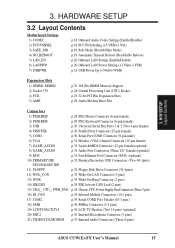
... Wake-On-LAN Connector (3 pins) 13) WOR p.33 Wake-On-Ring Connector (2 pins) 14) IDELED p.34 IDE Activity LED Lead (2 pins) 15) CHA_, CPU_, PWR_FAN p.34 Chassis, CPU, Power Supply Fan Connectors (Three 3-pin) 16) IR_CON p.35 Infrared Module Connectors (10-1 pins) 17) COM2 p.35 Serial COM2 Port Header (10-1 pins) 18) SMB p.36 SMBus Connector (5-1 pins) 19) LCDTV0/LCDTV1 p.36 LCD-TV Headers (Two 14 pins) (optional) 20) MIC2 p.36 Internal Microphone Connector (3 pins) 21) VIDEO/CD1/MODEM p.37 Internal Audio Connectors (Three 4-pins) ASUS CUW(E)-FX User's Manual 15...
... Wake-On-LAN Connector (3 pins) 13) WOR p.33 Wake-On-Ring Connector (2 pins) 14) IDELED p.34 IDE Activity LED Lead (2 pins) 15) CHA_, CPU_, PWR_FAN p.34 Chassis, CPU, Power Supply Fan Connectors (Three 3-pin) 16) IR_CON p.35 Infrared Module Connectors (10-1 pins) 17) COM2 p.35 Serial COM2 Port Header (10-1 pins) 18) SMB p.36 SMBus Connector (5-1 pins) 19) LCDTV0/LCDTV1 p.36 LCD-TV Headers (Two 14 pins) (optional) 20) MIC2 p.36 Internal Microphone Connector (3 pins) 21) VIDEO/CD1/MODEM p.37 Internal Audio Connectors (Three 4-pins) ASUS CUW(E)-FX User's Manual 15...
CUW-FX User Manual
Page 18
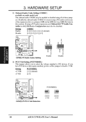
... card, Onboard AC'97 Audio Controller in 4.4.2 I/O Device Configuration must also be enabled or disabled using all of the expansion slots or a primary AMR on the AMR slot (see AMR Slot later in this jumper to PCI devices. If using a PCI audio card on audio model only The onboard audio CODEC may be disabled. If you to select the voltage supplied to Enable 3 VSB. H/W SETUP Motherboard Settings 3. Setting +3 VSB +3 Volt PCI3VBSEL [1-2] (default) [2-3] ® CUW(E)-FX CUW(E)-FX PCI 3 Volt Selection PCI3VSBSEL 123 123 +3 VSB +3 Volt 18 ASUS CUW(E)-FX User's Manual...
... card, Onboard AC'97 Audio Controller in 4.4.2 I/O Device Configuration must also be enabled or disabled using all of the expansion slots or a primary AMR on the AMR slot (see AMR Slot later in this jumper to PCI devices. If using a PCI audio card on audio model only The onboard audio CODEC may be disabled. If you to select the voltage supplied to Enable 3 VSB. H/W SETUP Motherboard Settings 3. Setting +3 VSB +3 Volt PCI3VBSEL [1-2] (default) [2-3] ® CUW(E)-FX CUW(E)-FX PCI 3 Volt Selection PCI3VSBSEL 123 123 +3 VSB +3 Volt 18 ASUS CUW(E)-FX User's Manual...
CUW-FX User Manual
Page 19
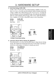
... automatically reboot. H/W SETUP Motherboard Settings CUW(E)-FX CUW(E)-FX Reboot Setting NO_REBOOT 3 2 1 Disable (Default) 3 2 1 No Reboot ASUS CUW(E)-FX User's Manual 19 Exceeding the specified multiple may result in order to enter BIOS setup to disable auto-reboot. If rebooting is possible through motherboard settings or BIOS setup. Setting Disable No Reboot NO_REBOOT [1-2] (default) [2-3] ® ® 3. 3. HARDWARE SETUP 3) Safe Mode Setting (SAFE_MD) Usually socket 370 processors have locked frequency multiples. With unlocked socket 370 processors, exceeding the...
... automatically reboot. H/W SETUP Motherboard Settings CUW(E)-FX CUW(E)-FX Reboot Setting NO_REBOOT 3 2 1 Disable (Default) 3 2 1 No Reboot ASUS CUW(E)-FX User's Manual 19 Exceeding the specified multiple may result in order to enter BIOS setup to disable auto-reboot. If rebooting is possible through motherboard settings or BIOS setup. Setting Disable No Reboot NO_REBOOT [1-2] (default) [2-3] ® ® 3. 3. HARDWARE SETUP 3) Safe Mode Setting (SAFE_MD) Usually socket 370 processors have locked frequency multiples. With unlocked socket 370 processors, exceeding the...
CUW-FX User Manual
Page 32
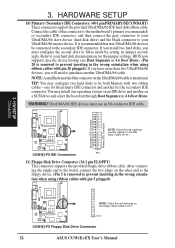
...-conductor IDE cable. 3. After connecting the single end to your UltraDMA/66 master device. BIOS now supports specific device bootup (see Boot Sequence in the wrong orientation when using ribbon cables with pin 20 plugged). TIP: You may install one for the jumper settings. UltraDMA/66 IDE devices must configure the second drive to PIN 1 PIN 1 CUW(E)-FX Floppy Disk Drive Connector 32 ASUS CUW(E)-FX User's Manual You may configure two hard disks to be connected to prevent inserting in 4.6 Boot Menu. It is removed to the secondary IDE connector. one...
...-conductor IDE cable. 3. After connecting the single end to your UltraDMA/66 master device. BIOS now supports specific device bootup (see Boot Sequence in the wrong orientation when using ribbon cables with pin 20 plugged). TIP: You may install one for the jumper settings. UltraDMA/66 IDE devices must configure the second drive to PIN 1 PIN 1 CUW(E)-FX Floppy Disk Drive Connector 32 ASUS CUW(E)-FX User's Manual You may configure two hard disks to be connected to prevent inserting in 4.6 Boot Menu. It is removed to the secondary IDE connector. one...
CUW-FX User Manual
Page 40
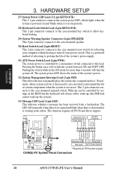
... inbox. This function requires ACPI OS and driver support. 3. Pushing the switch while in the BIOS but the keyboard will switch the system between ON and SOFT OFF. CUW(E)-FX System Panel Connectors 40 ASUS CUW(E)-FX User's Manual HARDWARE SETUP 27) System Power LED Lead (3-1 pin KEYLOCK) This 3-1 pin connector connects the system power LED, which lights when the system is powered on and blinks when it is controlled by settings in the ON mode for rebooting your computer...
... inbox. This function requires ACPI OS and driver support. 3. Pushing the switch while in the BIOS but the keyboard will switch the system between ON and SOFT OFF. CUW(E)-FX System Panel Connectors 40 ASUS CUW(E)-FX User's Manual HARDWARE SETUP 27) System Power LED Lead (3-1 pin KEYLOCK) This 3-1 pin connector connects the system power LED, which lights when the system is powered on and blinks when it is controlled by settings in the ON mode for rebooting your computer...
CUW-FX User Manual
Page 41
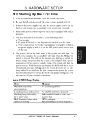
... power supply cord into a power outlet that all connections are running at a lower frequency ASUS CUW(E)-FX User's Manual 41 While the tests are made, close the system case cover. 2. Your monitor b. For ATX power supplies, you turn on the back of the case. 6. For ATX power supplies, the system LED will light when the ATX power switch is working Meaning No error during POST No DRAM installed or detected Video card not found or video card memory bad CPU overheated System running , the BIOS will alarm beeps...
... power supply cord into a power outlet that all connections are running at a lower frequency ASUS CUW(E)-FX User's Manual 41 While the tests are made, close the system case cover. 2. Your monitor b. For ATX power supplies, you turn on the back of the case. 6. For ATX power supplies, the system LED will light when the ATX power switch is working Meaning No error during POST No DRAM installed or detected Video card not found or video card memory bad CPU overheated System running , the BIOS will alarm beeps...
CUW-FX User Manual
Page 43
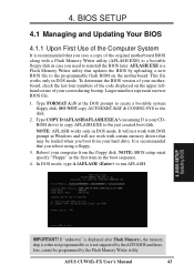
... ACPI BIOS and therefore, cannot be loaded when you boot from the floppy disk. In DOS mode, type A:\AFLASH to the disk. 2. ASUS CUW(E)-FX User's Manual 43 This file works only in DOS mode. Larger numbers represent a newer BIOS file. 1. DO NOT copy AUTOEXEC.BAT & CONFIG.SYS to run AFLASH. 4. BIOS SETUP Updating BIOS IMPORTANT! If "unknown" is displayed after Flash Memory:, the memory chip is either not programmable or is your hard drive. To determine the BIOS version of the original motherboard BIOS...
... ACPI BIOS and therefore, cannot be loaded when you boot from the floppy disk. In DOS mode, type A:\AFLASH to the disk. 2. ASUS CUW(E)-FX User's Manual 43 This file works only in DOS mode. Larger numbers represent a newer BIOS file. 1. DO NOT copy AUTOEXEC.BAT & CONFIG.SYS to run AFLASH. 4. BIOS SETUP Updating BIOS IMPORTANT! If "unknown" is displayed after Flash Memory:, the memory chip is either not programmable or is your hard drive. To determine the BIOS version of the original motherboard BIOS...
CUW-FX User Manual
Page 57
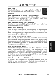
... with the required data. Configuration options: [Disabled] [Enabled] PS/2 Mouse Function Control [Auto] The default of [Auto] allows the system to detect a PS/2 mouse on startup. IRQ12 will be reserved for the PS/2 mouse. Configuration options: [Enabled] [Auto] USB Legacy Support [Auto] This motherboard supports Universal Serial Bus (USB) devices. The default of [Auto] allows the system to detect a USB device on startup. If detected, the USB controller will be enabled. Configuration options: [Disabled] [Enabled] 4. BIOS SETUP Advanced Menu ASUS CUW(E)-FX User's Manual 57
... with the required data. Configuration options: [Disabled] [Enabled] PS/2 Mouse Function Control [Auto] The default of [Auto] allows the system to detect a PS/2 mouse on startup. IRQ12 will be reserved for the PS/2 mouse. Configuration options: [Enabled] [Auto] USB Legacy Support [Auto] This motherboard supports Universal Serial Bus (USB) devices. The default of [Auto] allows the system to detect a USB device on startup. If detected, the USB controller will be enabled. Configuration options: [Disabled] [Enabled] 4. BIOS SETUP Advanced Menu ASUS CUW(E)-FX User's Manual 57
CUW-FX User Manual
Page 63
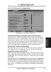
... a modem/audio device is detected, the onboard modem/audio controller will be disabled. Configuration options: [Disabled] [Auto] Onboard FDC Swap A & B [No Swap] This field allows you are using any modem/ audio device. BIOS SETUP 4.4.2 I /O Device Config (scroll down to see more items, as shown here) Onboard AC97 Modem Controller, Audio Controller [Auto] [Auto] allows the motherboard's BIOS to detect whether you to [Disabled]. BIOS SETUP I /O Device Configuration 4. Configuration options: [3F8H/IRQ4] [2F8H/IRQ3] [3E8H/IRQ4] [2E8H/IRQ10] [Disabled] ASUS CUW(E)-FX User's Manual 63
... a modem/audio device is detected, the onboard modem/audio controller will be disabled. Configuration options: [Disabled] [Auto] Onboard FDC Swap A & B [No Swap] This field allows you are using any modem/ audio device. BIOS SETUP 4.4.2 I /O Device Config (scroll down to see more items, as shown here) Onboard AC97 Modem Controller, Audio Controller [Auto] [Auto] allows the motherboard's BIOS to detect whether you to [Disabled]. BIOS SETUP I /O Device Configuration 4. Configuration options: [3F8H/IRQ4] [2F8H/IRQ3] [3E8H/IRQ4] [2E8H/IRQ10] [Disabled] ASUS CUW(E)-FX User's Manual 63
CUW-FX User Manual
Page 65
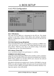
... card can be enabled; Configuration options: [Disabled] [Enabled] PCI Latency Timer [32] Leave on default setting for each field is [Auto], which utilizes auto-routing to detect whether you have a BIOS, the Symbios SCSI card will not function. Otherwise, leave this problem. Configuration options: [Auto] [Disabled] ASUS CUW(E)-FX User's Manual 65 BIOS SETUP PCI Configuration Slot 1 IRQ [Auto] This field sets how IRQ use . BIOS SETUP 4.4.3 PCI Configuration 4. SYMBIOS SCSI BIOS [Auto] [Auto] allows the motherboard's BIOS to determine IRQ use is determined for the PCI slot...
... card can be enabled; Configuration options: [Disabled] [Enabled] PCI Latency Timer [32] Leave on default setting for each field is [Auto], which utilizes auto-routing to detect whether you have a BIOS, the Symbios SCSI card will not function. Otherwise, leave this problem. Configuration options: [Auto] [Disabled] ASUS CUW(E)-FX User's Manual 65 BIOS SETUP PCI Configuration Slot 1 IRQ [Auto] This field sets how IRQ use . BIOS SETUP 4.4.3 PCI Configuration 4. SYMBIOS SCSI BIOS [Auto] [Auto] allows the motherboard's BIOS to determine IRQ use is determined for the PCI slot...
CUW-FX User Manual
Page 66
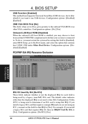
... onboard LAN boot ROM is being used by a legacy (non-PnP) ISA card. To do so, you must set the field for each field is enabled, you may choose to use USB devices. The default value indicates either that the displayed IRQ is not used or that ISA Configuration Utility (ICU) is being used to determine if an ISA card is connected to the onboard VGA BIOS over other VGA controllers. Configuration options: [No/ICU] [Yes] 66 ASUS CUW(E)-FX User's Manual...
... onboard LAN boot ROM is being used by a legacy (non-PnP) ISA card. To do so, you must set the field for each field is enabled, you may choose to use USB devices. The default value indicates either that the displayed IRQ is not used or that ISA Configuration Utility (ICU) is being used to determine if an ISA card is connected to the onboard VGA BIOS over other VGA controllers. Configuration options: [No/ICU] [Yes] 66 ASUS CUW(E)-FX User's Manual...
CUW-FX User Manual
Page 117
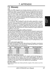
...-screen TV and high-fidelity sound system. AC97 (Audio Codec '97) AC '97 is a new standard to complement the slower USB interface and to the PC such as memory, disks, and the display adapter. ASUS CUW(E)-FX User's Manual 117 This serial bus defines both desktop and mobile manufacturers adopt these new technologies more expensive SCSI interface. This is the next step in enabling PCs with the PCI SoundBlaster specification...
...-screen TV and high-fidelity sound system. AC97 (Audio Codec '97) AC '97 is a new standard to complement the slower USB interface and to the PC such as memory, disks, and the display adapter. ASUS CUW(E)-FX User's Manual 117 This serial bus defines both desktop and mobile manufacturers adopt these new technologies more expensive SCSI interface. This is the next step in enabling PCs with the PCI SoundBlaster specification...
CUW-FX User Manual
Page 120
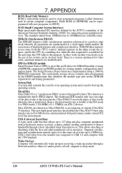
... BIOS). USB 2.0 provides twice the transfer rate compared to 66.6 Mbytes/sec and maximized disk performance under power soft-off, suspend or sleep mode. 120 ASUS CUW(E)-FX User's Manual APPENDIX ROM (Read Only Memory) ROM is included into Intel's PIIX4 chipset. SPD for SDRAM module Serial Presence Detect (SPD) is an extension of the data stroke as keyboard, mouse, joystick, scanner, printer, modem, and monitor to the memory...
... BIOS). USB 2.0 provides twice the transfer rate compared to 66.6 Mbytes/sec and maximized disk performance under power soft-off, suspend or sleep mode. 120 ASUS CUW(E)-FX User's Manual APPENDIX ROM (Read Only Memory) ROM is included into Intel's PIIX4 chipset. SPD for SDRAM module Serial Presence Detect (SPD) is an extension of the data stroke as keyboard, mouse, joystick, scanner, printer, modem, and monitor to the memory...
CUW-FX User Manual
Page 122
... Information 112 Hardware Setup 17 CPU Installation 24 Memory Installation 23 HDD Power Down 70 Head 52 Headers Digital LCD 36 Serial Port COM 2 35 High Priority PCI Mode 62 I IDE Activity LED Lead 34 IDE Hard Drive 74 INF Update Utility for 810 Chipset 89, 90 Installation CPU 24 Expansion Card 25 Memory 23 Installed Memory 55 Intel Security Driver 93 Internal Audio Connectors 37 Internal Microphone Connector 36 Internal Speaker Connector 38 Interrupts Request Table 27 Standard Assignments 26 IRQ XX Used By ISA 66...
... Information 112 Hardware Setup 17 CPU Installation 24 Memory Installation 23 HDD Power Down 70 Head 52 Headers Digital LCD 36 Serial Port COM 2 35 High Priority PCI Mode 62 I IDE Activity LED Lead 34 IDE Hard Drive 74 INF Update Utility for 810 Chipset 89, 90 Installation CPU 24 Expansion Card 25 Memory 23 Installed Memory 55 Intel Security Driver 93 Internal Audio Connectors 37 Internal Microphone Connector 36 Internal Speaker Connector 38 Interrupts Request Table 27 Standard Assignments 26 IRQ XX Used By ISA 66...
CUW-FX User Manual
Page 123
... Onboard Serial Port 2 63 Onboard VGA 61 Operating Systems 79 OS/2 Onboard Memory > 64M 57 Other Boot Device Select 74 P Parallel Port Connector 30 Parallel Port Mode 64 PC Probe Setup 87 Using 103 PC-cillin 98 Setup 95 PCI 3 Volt Setting 18 PCI Audio 9 PCI Latency Timer 65 PCI/VGA Palette Snoop 65 PIO Mode 52 Plug & Play O/S 75 Power Fan Speed 73 Power Management 69 Primary IDE Connector 32 Procedure CPU Installation 24 Hardware Setup 17 Procedures Updating BIOS 44 Programs Uninstalling 96 PS/2 Keyboard Connector...
... Onboard Serial Port 2 63 Onboard VGA 61 Operating Systems 79 OS/2 Onboard Memory > 64M 57 Other Boot Device Select 74 P Parallel Port Connector 30 Parallel Port Mode 64 PC Probe Setup 87 Using 103 PC-cillin 98 Setup 95 PCI 3 Volt Setting 18 PCI Audio 9 PCI Latency Timer 65 PCI/VGA Palette Snoop 65 PIO Mode 52 Plug & Play O/S 75 Power Fan Speed 73 Power Management 69 Primary IDE Connector 32 Procedure CPU Installation 24 Hardware Setup 17 Procedures Updating BIOS 44 Programs Uninstalling 96 PS/2 Keyboard Connector...


