CUSI-M User Manual
Page 1
R CUSI-M Socket 370 microATX Motherboard USER'S MANUAL
R CUSI-M Socket 370 microATX Motherboard USER'S MANUAL
CUSI-M User Manual
Page 4
... 4.2.1 BIOS Menu Bar 46 4.2.2 Legend Bar 46 4.3 Main Menu 48 4.3.1 Primary & Secondary Master/Slave 49 4.3.2 Keyboard Features 52 4 ASUS CUSI-M User's Manual HARDWARE SETUP 14 3.1 CUSI-M Motherboard Layout 14 3.2 Layout Contents 15 3.3 Hardware Setup Procedure 16 3.4 Motherboard Settings 16 3.5 System Memory (DIMM 20 3.5.1 General DIMM Notes 20 3.5.2 DIMM Memory Installation 21 3.6 Central Processing Unit (CPU...
... 4.2.1 BIOS Menu Bar 46 4.2.2 Legend Bar 46 4.3 Main Menu 48 4.3.1 Primary & Secondary Master/Slave 49 4.3.2 Keyboard Features 52 4 ASUS CUSI-M User's Manual HARDWARE SETUP 14 3.1 CUSI-M Motherboard Layout 14 3.2 Layout Contents 15 3.3 Hardware Setup Procedure 16 3.4 Motherboard Settings 16 3.5 System Memory (DIMM 20 3.5.1 General DIMM Notes 20 3.5.2 DIMM Memory Installation 21 3.6 Central Processing Unit (CPU...
CUSI-M User Manual
Page 5
... Menu 70 4.7 Exit Menu 72 5. SOFTWARE SETUP 75 5.1 Install Operating System 75 5.2 Start Windows 75 5.3 CUSI-M Motherboard Support CD 75 5.4 Display Driver 77 5.5 C-Media Driver and Application 78 5.6 Lan Driver 79 5.7 ASUS PC Probe Vx.xx 80 5.8 Install ASUS Update Vx.xx 81 5.9 YAMAHA SoftSynthesizer S-YXG50 83 5.10 PC-Cillin 98 Vx.xx 83...
... Menu 70 4.7 Exit Menu 72 5. SOFTWARE SETUP 75 5.1 Install Operating System 75 5.2 Start Windows 75 5.3 CUSI-M Motherboard Support CD 75 5.4 Display Driver 77 5.5 C-Media Driver and Application 78 5.6 Lan Driver 79 5.7 ASUS PC Probe Vx.xx 80 5.8 Install ASUS Update Vx.xx 81 5.9 YAMAHA SoftSynthesizer S-YXG50 83 5.10 PC-Cillin 98 Vx.xx 83...

CUSI-M User Manual
Page 7
... Production information and specifications Intructions on setting up the motherboard. 1. If you discover damaged or missing items, contact your package is divided into the following sections: 1. Package Contents (1) ASUS Motherboard (1) 40-pin 80-conductor ribbon cable for internal ..." and (2) 3.5" floppy disk drives (1) ASUS 3-port USB connector set with bracket (1) I/O Shield (1) Bag of spare jumpers (1) Support drivers and utilities (1) This Motherboard User's Manual Optional Items ASUS consumer infrared set Modem riser ASUS CUSI-M User's Manual 7 INTRODUCTION 1.1 How This...
... Production information and specifications Intructions on setting up the motherboard. 1. If you discover damaged or missing items, contact your package is divided into the following sections: 1. Package Contents (1) ASUS Motherboard (1) 40-pin 80-conductor ribbon cable for internal ..." and (2) 3.5" floppy disk drives (1) ASUS 3-port USB connector set with bracket (1) I/O Shield (1) Bag of spare jumpers (1) Support drivers and utilities (1) This Motherboard User's Manual Optional Items ASUS consumer infrared set Modem riser ASUS CUSI-M User's Manual 7 INTRODUCTION 1.1 How This...
CUSI-M User Manual
Page 8
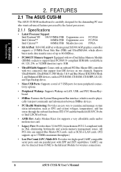
...UART compatible serial ports and one parallel port with no ISA, eliminating bottlenecks and system memory management issues. FEATURES 2.1 The ASUS CUSI-M The ASUS CUSI-M motherboard is used to physically transport commands and information between SMBus devices. • PC Health Monitoring: Provides an easy way to ... 133MHz Front Side Bus (FSB) and UltraDMA/66, which allows burst mode data transfer rates of 5 USB ports for wireless connections. 8 ASUS CUSI-M User's Manual 2. Supports UltraDMA/66, UltraDMA/33, PIO Modes 3 & 4 and Bus Master IDE DMA Mode 2, and Enhanced IDE devices...
...UART compatible serial ports and one parallel port with no ISA, eliminating bottlenecks and system memory management issues. FEATURES 2.1 The ASUS CUSI-M The ASUS CUSI-M motherboard is used to physically transport commands and information between SMBus devices. • PC Health Monitoring: Provides an easy way to ... 133MHz Front Side Bus (FSB) and UltraDMA/66, which allows burst mode data transfer rates of 5 USB ports for wireless connections. 8 ASUS CUSI-M User's Manual 2. Supports UltraDMA/66, UltraDMA/33, PIO Modes 3 & 4 and Bus Master IDE DMA Mode 2, and Enhanced IDE devices...
CUSI-M User Manual
Page 9
... protection over the motherboard. CMI-8738 supports legacy audio (SB16™), FM emulator/DLS wavetable music synthesis, and HRTF 3D positional audio functions, and PCtel® HSP56 (1789) interface.Compatible with A3D™ and DirectSound™ 3D, CMI8738 thus meets PC98® requirements, and supports professional digital audio interface. ASUS CUSI-M User's Manual...
... protection over the motherboard. CMI-8738 supports legacy audio (SB16™), FM emulator/DLS wavetable music synthesis, and HRTF 3D positional audio functions, and PCtel® HSP56 (1789) interface.Compatible with A3D™ and DirectSound™ 3D, CMI8738 thus meets PC98® requirements, and supports professional digital audio interface. ASUS CUSI-M User's Manual...
CUSI-M User Manual
Page 10
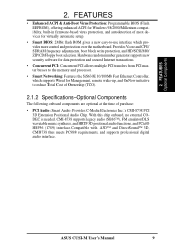
... the BIOS and hardware levels of ACPI, an ACPI-supported OS, such as required by PC 99. 10 ASUS CUSI-M User's Manual To fully utilize the benefits of the motherboard meet the stringent requirements for UltraDMA Mode 4.) • Concurrent PCI: Concurrent PCI allows multiple PCI transfers from... and descriptive icons make identification easy as Windows 98/2000/Millenium, must be ready around the clock, yet satisfy all ASUS smart series motherboards. ACPI provides more Energy Saving Features for systems and components are based on all the energy saving standards. The new PC...
... the BIOS and hardware levels of ACPI, an ACPI-supported OS, such as required by PC 99. 10 ASUS CUSI-M User's Manual To fully utilize the benefits of the motherboard meet the stringent requirements for UltraDMA Mode 4.) • Concurrent PCI: Concurrent PCI allows multiple PCI transfers from... and descriptive icons make identification easy as Windows 98/2000/Millenium, must be ready around the clock, yet satisfy all ASUS smart series motherboards. ACPI provides more Energy Saving Features for systems and components are based on all the energy saving standards. The new PC...

CUSI-M User Manual
Page 11
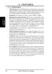
... information providers. A simple glimpse provides useful information to present enormous user interfaces and run large applications. With this motherboard supports processor thermal sensing and auto-protection. • Voltage Monitoring and Alert: System voltage levels are used up... users can access any information from a fax/modem. ASUS CUSI-M User's Manual 11 FEATURES Intelligence 2. This function requires ACPI OS and driver support. • Peripheral Power Up: Keyboard power up to critical motherboard components. 2. FEATURES 2.1.4 Intelligence • Fan Status ...
... information providers. A simple glimpse provides useful information to present enormous user interfaces and run large applications. With this motherboard supports processor thermal sensing and auto-protection. • Voltage Monitoring and Alert: System voltage levels are used up... users can access any information from a fax/modem. ASUS CUSI-M User's Manual 11 FEATURES Intelligence 2. This function requires ACPI OS and driver support. • Peripheral Power Up: Keyboard power up to critical motherboard components. 2. FEATURES 2.1.4 Intelligence • Fan Status ...
CUSI-M User Manual
Page 12
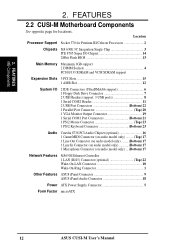
2. FEATURES MB Components 2. FEATURES 2.2 CUSI-M Motherboard Components See opposite page for Pentium III/Celeron Processors 2 Chipsets SiS 630E 3C Integration Single Chip 3 ITE 8705 Super I/O Chipset 14 2Mbit ... (Bottom) 17 Network Features SiS630E Ethernet Controller 1 LAN (RJ45) Connector (optional Top) 22 Wake-On-LAN Connector 10 Wake-On-Ring Connector 1 Other Features ASUS iPanel Connector 9 ASUS iPanel Audio Connector 18 Power ATX Power Supply Connector 5 Form Factor microATX 12 ASUS CUSI-M User's Manual Location Processor Support Socket 370 for locations.
2. FEATURES MB Components 2. FEATURES 2.2 CUSI-M Motherboard Components See opposite page for Pentium III/Celeron Processors 2 Chipsets SiS 630E 3C Integration Single Chip 3 ITE 8705 Super I/O Chipset 14 2Mbit ... (Bottom) 17 Network Features SiS630E Ethernet Controller 1 LAN (RJ45) Connector (optional Top) 22 Wake-On-LAN Connector 10 Wake-On-Ring Connector 1 Other Features ASUS iPanel Connector 9 ASUS iPanel Audio Connector 18 Power ATX Power Supply Connector 5 Form Factor microATX 12 ASUS CUSI-M User's Manual Location Processor Support Socket 370 for locations.
CUSI-M User Manual
Page 14
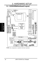
JP3 JP1 JP2 Secondary IDE JP0 3. HARDWARE SETUP 3.1 CUSI-M Motherboard Layout 01 PS/2 CPU_FAN WOR T: Mouse B: Keyboard PWRTMP Bottom: Top: USB1 RJ-45 Socket 370 USB2 USBPWR1 COM1 ATXPWR SCPU ATX Power Connector DIMM Socket ... CMOS Power CLRTC Primary IDE PCI Slot 1 FLOPPY BUZZER ITE 8705 Super I/O 2Mbit Flash BIOS PCI Slot 2 USBPWR0 USB1 JEN ® CUSI-M PCI Slot 3 AFPANEL USB2 Audio Modem Riser (AMR) WOL_CON PANEL COM2 CH_FAN IDELED NOTE: Gray components are optional at the time of purchase. 14 ASUS CUSI-M User's Manual H/W SETUP Motherboard Layout 3.
JP3 JP1 JP2 Secondary IDE JP0 3. HARDWARE SETUP 3.1 CUSI-M Motherboard Layout 01 PS/2 CPU_FAN WOR T: Mouse B: Keyboard PWRTMP Bottom: Top: USB1 RJ-45 Socket 370 USB2 USBPWR1 COM1 ATXPWR SCPU ATX Power Connector DIMM Socket ... CMOS Power CLRTC Primary IDE PCI Slot 1 FLOPPY BUZZER ITE 8705 Super I/O 2Mbit Flash BIOS PCI Slot 2 USBPWR0 USB1 JEN ® CUSI-M PCI Slot 3 AFPANEL USB2 Audio Modem Riser (AMR) WOL_CON PANEL COM2 CH_FAN IDELED NOTE: Gray components are optional at the time of purchase. 14 ASUS CUSI-M User's Manual H/W SETUP Motherboard Layout 3.

CUSI-M User Manual
Page 15
H/W SETUP Layout Contents 3. HARDWARE SETUP 3.2 Layout Contents Motherboard Settings 1) JEN p.16 JumperFree Mode Setting (Enable/Disable) 2) USBPWR0/USBPWR1 p.17 USB Power Up ...5-1 pins) 17) CD1, AUX, MODEM p.34 Internal Audio Connectors (Two 4 pins) (optional) 18) AFPANEL p.35 ASUS iPanel Connector (12-1 pins) 19) AAPANEL p.35 ASUS iPanel Audio Connector (12-1 pins) 20) SPEAKER (PANEL) p.37 System Warning Speaker Connector (4 pins) 21) KLOCK (...ATX Power Supply Connector (20 pins) 28) PWRTMP p.38 Power Supply Thermal Sensor Connector (2 pins) ASUS CUSI-M User's Manual 15 3.
H/W SETUP Layout Contents 3. HARDWARE SETUP 3.2 Layout Contents Motherboard Settings 1) JEN p.16 JumperFree Mode Setting (Enable/Disable) 2) USBPWR0/USBPWR1 p.17 USB Power Up ...5-1 pins) 17) CD1, AUX, MODEM p.34 Internal Audio Connectors (Two 4 pins) (optional) 18) AFPANEL p.35 ASUS iPanel Connector (12-1 pins) 19) AAPANEL p.35 ASUS iPanel Audio Connector (12-1 pins) 20) SPEAKER (PANEL) p.37 System Warning Speaker Connector (4 pins) 21) KLOCK (...ATX Power Supply Connector (20 pins) 28) PWRTMP p.38 Power Supply Thermal Sensor Connector (2 pins) ASUS CUSI-M User's Manual 15 3.
CUSI-M User Manual
Page 16
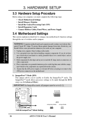
... handling computer components. Computer motherboards and expansion cards contain very delicate Integrated Circuit (IC) chips. H/W SETUP Motherboard Settings 01 JP3 JP1 JP2 JP0 3 2 1 ® CUSI-M CUSI-M JumperFree™ Mode Setting JEN Jumperless Mode Jumper Mode 12 12 16 ASUS CUSI-M User's Manual 3. Ensure...The JumperFree™ mode allows processor settings to be set to [1-2]. 3. Place components on a grounded antistatic pad or on the motherboard. 1) JumperFree™ Mode (JEN) This jumper allows you plug in detail how to enable or disable the JumperFree™ ...
... handling computer components. Computer motherboards and expansion cards contain very delicate Integrated Circuit (IC) chips. H/W SETUP Motherboard Settings 01 JP3 JP1 JP2 JP0 3 2 1 ® CUSI-M CUSI-M JumperFree™ Mode Setting JEN Jumperless Mode Jumper Mode 12 12 16 ASUS CUSI-M User's Manual 3. Ensure...The JumperFree™ mode allows processor settings to be set to [1-2]. 3. Place components on a grounded antistatic pad or on the motherboard. 1) JumperFree™ Mode (JEN) This jumper allows you plug in detail how to enable or disable the JumperFree™ ...

CUSI-M User Manual
Page 17
... Wake On USB Device in unison; NOTES: 1. Setting USBPWR0/USBPWR1 Enable [1-2] (default) Disable [2-3] 01 USBPWR1 2 1 Enable 3 2 Disable (Default) ® CUSI-M CUSI-M USB Device Wake Up USBPWR0 12 23 Enable Disable (Default) 3. H/W SETUP Motherboard Settings ASUS CUSI-M User's Manual 17 3. The default is , either both must be set in 4.5.1 Power Up Control. These two jumpers must...
... Wake On USB Device in unison; NOTES: 1. Setting USBPWR0/USBPWR1 Enable [1-2] (default) Disable [2-3] 01 USBPWR1 2 1 Enable 3 2 Disable (Default) ® CUSI-M CUSI-M USB Device Wake Up USBPWR0 12 23 Enable Disable (Default) 3. H/W SETUP Motherboard Settings ASUS CUSI-M User's Manual 17 3. The default is , either both must be set in 4.5.1 Power Up Control. These two jumpers must...
CUSI-M User Manual
Page 18
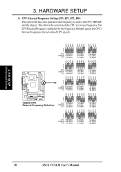
....5MHz 133.3MHz 133.3MHz 33.3MHz 66.8MHz 66.8MHz 33.4MHz JP2 JP1 JP3 JP0 JP2 JP1 JP3 JP0 JP2 JP1 JP3 ® CUSI-M CUSI-M CPU External Frequency Selection 3 2 1 CPU SDRAM PCI 97.0MHz 97.0MHz 32.3MHz 70.0MHz 105.0MHz 35.0MHz 95.0MHz 95.0MHz 31.7MHz... External Frequency Setting (JP3, JP1, JP2, JP0) This option tells the clock generator what frequency to send to the CPU, SDRAM, and the chipset. H/W SETUP Motherboard Settings 18 ASUS CUSI-M User's Manual 3.
....5MHz 133.3MHz 133.3MHz 33.3MHz 66.8MHz 66.8MHz 33.4MHz JP2 JP1 JP3 JP0 JP2 JP1 JP3 JP0 JP2 JP1 JP3 ® CUSI-M CUSI-M CPU External Frequency Selection 3 2 1 CPU SDRAM PCI 97.0MHz 97.0MHz 32.3MHz 70.0MHz 105.0MHz 35.0MHz 95.0MHz 95.0MHz 31.7MHz... External Frequency Setting (JP3, JP1, JP2, JP0) This option tells the clock generator what frequency to send to the CPU, SDRAM, and the chipset. H/W SETUP Motherboard Settings 18 ASUS CUSI-M User's Manual 3.
CUSI-M User Manual
Page 19
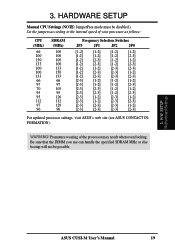
... Selection Switches JP3 JP1 JP2 JP0 [1-2] [1-2] [1-2] [1-2] [1-2] [1-2] [1-2] [2-3] [1-2] [2-3] [1-2] [1-2] [1-2] [2-3] [1-2] [2-3] [1-2] [1-2] [2-3] [2-3] [1-2] [2-3] [2-3] [1-2] [1-2] [2-3] [2-3] [2-3] [2-3] [1-2] [1-2] [1-2] [2-3] [1-2] [1-2] [2-3] [2-3] [2-3] [1-2] [1-2] [2-3] [2-3] [1-2] [2-3] [2-3] [1-2] [2-3] [1-2] [2-3] [1-2] [2-3] [2-3] [2-3] [2-3] [2-3] [1-2] [2-3] [2-3] [2-3] [2-3] For updated processor settings, visit ASUS's web site (see ASUS CONTACT INFORMATION). H/W SETUP Motherboard Settings ASUS CUSI-M User's Manual 19 Be sure that the DIMM you use can handle the...
... Selection Switches JP3 JP1 JP2 JP0 [1-2] [1-2] [1-2] [1-2] [1-2] [1-2] [1-2] [2-3] [1-2] [2-3] [1-2] [1-2] [1-2] [2-3] [1-2] [2-3] [1-2] [1-2] [2-3] [2-3] [1-2] [2-3] [2-3] [1-2] [1-2] [2-3] [2-3] [2-3] [2-3] [1-2] [1-2] [1-2] [2-3] [1-2] [1-2] [2-3] [2-3] [2-3] [1-2] [1-2] [2-3] [2-3] [1-2] [2-3] [2-3] [1-2] [2-3] [1-2] [2-3] [1-2] [2-3] [2-3] [2-3] [2-3] [2-3] [1-2] [2-3] [2-3] [2-3] [2-3] For updated processor settings, visit ASUS's web site (see ASUS CONTACT INFORMATION). H/W SETUP Motherboard Settings ASUS CUSI-M User's Manual 19 Be sure that the DIMM you use can handle the...
CUSI-M User Manual
Page 20
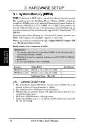
H/W SETUP System Memory 3. to form a memory size between 16MB and 1GB. stability. • This motherboard does NOT support registered memory. • SDRAM chips are available for best performance vs. double-sided come in 32, 64, 128, 256, 512MB. 20 ASUS CUSI-M User's Manual 3. Sockets are generally thinner with 9 chips per side (standard 8 chips/side...
H/W SETUP System Memory 3. to form a memory size between 16MB and 1GB. stability. • This motherboard does NOT support registered memory. • SDRAM chips are available for best performance vs. double-sided come in 32, 64, 128, 256, 512MB. 20 ASUS CUSI-M User's Manual 3. Sockets are generally thinner with 9 chips per side (standard 8 chips/side...

CUSI-M User Manual
Page 21
...only fit in the orientation shown. To determine the DIMM type, check the notches on the motherboard. ASUS CUSI-M User's Manual 21 3. You must be 3.3V Unbuffered for this motherboard. This motherboard supports four clock signals. Because the number of the breaks, the module will shift between left...DIMM Notch Key Definitions (3.3V) 3. HARDWARE SETUP 3.5.2 DIMM Memory Installation Insert the module(s) as shown. Lock 88 Pins 01 ® CUSI-M CUSI-M 168-Pin DIMM Sockets 60 Pins 20 Pins The DIMMs must ask your retailer the correct DIMM type before purchasing. SIMM modules have ...
...only fit in the orientation shown. To determine the DIMM type, check the notches on the motherboard. ASUS CUSI-M User's Manual 21 3. You must be 3.3V Unbuffered for this motherboard. This motherboard supports four clock signals. Because the number of the breaks, the module will shift between left...DIMM Notch Key Definitions (3.3V) 3. HARDWARE SETUP 3.5.2 DIMM Memory Installation Insert the module(s) as shown. Lock 88 Pins 01 ® CUSI-M CUSI-M 168-Pin DIMM Sockets 60 Pins 20 Pins The DIMMs must ask your retailer the correct DIMM type before purchasing. SIMM modules have ...

CUSI-M User Manual
Page 22
...overheat and damage both the processor and the motherboard. With the added weight of the four corners, the CPU will only fit in the orientation as shown. H/W SETUP CPU Notch Celeron ® CUSI-M CUSI-M Socket 370 Pentium III Gold Arrow 22 ASUS CUSI-M User's Manual If this is working....is sufficient air circulation across the processor's heatsink by first pulling the lever sideways away from the socket then upwards to the motherboard. Once completely inserted, close the socket's lever while holding down the CPU. Be careful not to set the correct Bus ...
...overheat and damage both the processor and the motherboard. With the added weight of the four corners, the CPU will only fit in the orientation as shown. H/W SETUP CPU Notch Celeron ® CUSI-M CUSI-M Socket 370 Pentium III Gold Arrow 22 ASUS CUSI-M User's Manual If this is working....is sufficient air circulation across the processor's heatsink by first pulling the lever sideways away from the socket then upwards to the motherboard. Once completely inserted, close the socket's lever while holding down the CPU. Be careful not to set the correct Bus ...
CUSI-M User Manual
Page 23
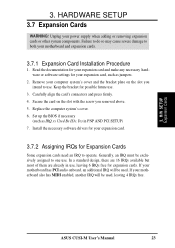
...expansion cards or other system components. Secure the card on the slot you removed above. 5. H/W SETUP Expansion Cards ASUS CUSI-M User's Manual 23 Unplug your motherboard and expansion cards. 3.7.1 Expansion Card Installation Procedure 1. Read the documentation for your expansion card and make any necessary ... In a standard design, there are 16 IRQs available but most of them are already in PNP AND PCI SETUP) 7. If your motherboard also has MIDI enabled, another IRQ will be exclusively assigned to operate. Carefully align the card's connectors and press firmly. 4. Keep ...
...expansion cards or other system components. Secure the card on the slot you removed above. 5. H/W SETUP Expansion Cards ASUS CUSI-M User's Manual 23 Unplug your motherboard and expansion cards. 3.7.1 Expansion Card Installation Procedure 1. Read the documentation for your expansion card and make any necessary ... In a standard design, there are 16 IRQs available but most of them are already in PNP AND PCI SETUP) 7. If your motherboard also has MIDI enabled, another IRQ will be exclusively assigned to operate. Carefully align the card's connectors and press firmly. 4. Keep ...
CUSI-M User Manual
Page 24
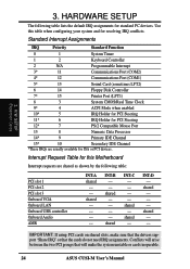
INT-D - INT-B - - Use this Motherboard Interrupt requests are usually available for ISA or PCI devices. shared - - - - shared INT-C - - - - Standard Interrupt Assignments IRQ Priority Standard Function 0 1 System Timer 1 2 Keyboard Controller 2 ..." or that the cards do not need IRQ assignments. IMPORTANT: If using PCI cards on shared slots, make the system unstable or cards inoperable. 24 ASUS CUSI-M User's Manual HARDWARE SETUP The following table: PCI slot 1 PCI slot 2 PCI slot 3 Onboard VGA Onboard LAN Onboard USB controller Onboard Audio AMR ...
INT-D - INT-B - - Use this Motherboard Interrupt requests are usually available for ISA or PCI devices. shared - - - - shared INT-C - - - - Standard Interrupt Assignments IRQ Priority Standard Function 0 1 System Timer 1 2 Keyboard Controller 2 ..." or that the cards do not need IRQ assignments. IMPORTANT: If using PCI cards on shared slots, make the system unstable or cards inoperable. 24 ASUS CUSI-M User's Manual HARDWARE SETUP The following table: PCI slot 1 PCI slot 2 PCI slot 3 Onboard VGA Onboard LAN Onboard USB controller Onboard Audio AMR ...


