
CUSI-M User Manual
Page 2
...and Acrobat are registered trademarks of Adobe Systems Incorporated. Copyright © 2000 ASUSTeK COMPUTER INC. Product Name: ASUS CUSI-M Manual Revision: 1.01 E605 Release Date: September 2000 2 ASUS CUSI-M User's Manual USER'S NOTICE No part of this manual may or may be reproduced, transmitted, transcribed, ...Manual revisions are registered trademarks of the manual revision number. For previous or updated manuals, BIOS, drivers, or product release information, contact ASUS at http://www.asus.com.tw or through any means, except documentation kept by the purchaser for each product...
...and Acrobat are registered trademarks of Adobe Systems Incorporated. Copyright © 2000 ASUSTeK COMPUTER INC. Product Name: ASUS CUSI-M Manual Revision: 1.01 E605 Release Date: September 2000 2 ASUS CUSI-M User's Manual USER'S NOTICE No part of this manual may or may be reproduced, transmitted, transcribed, ...Manual revisions are registered trademarks of the manual revision number. For previous or updated manuals, BIOS, drivers, or product release information, contact ASUS at http://www.asus.com.tw or through any means, except documentation kept by the purchaser for each product...
CUSI-M User Manual
Page 4
... 9 2.1.3 Performance 10 2.1.4 Intelligence 11 2.2 CUSI-M Motherboard Components 12 3. BIOS SETUP 41 4.1 Managing and Updating Your BIOS 41 4.1.1 Upon First Use of the Computer System 41 4.1.2 Updating BIOS Procedures 42 4.2 BIOS Setup Program 45 4.2.1 BIOS Menu Bar 46 4.2.2 Legend Bar 46 4.3 Main Menu 48 4.3.1 Primary & Secondary Master/Slave 49 4.3.2 Keyboard Features 52 4 ASUS CUSI-M User's Manual INTRODUCTION 7 1.1 How This...
... 9 2.1.3 Performance 10 2.1.4 Intelligence 11 2.2 CUSI-M Motherboard Components 12 3. BIOS SETUP 41 4.1 Managing and Updating Your BIOS 41 4.1.1 Upon First Use of the Computer System 41 4.1.2 Updating BIOS Procedures 42 4.2 BIOS Setup Program 45 4.2.1 BIOS Menu Bar 46 4.2.2 Legend Bar 46 4.3 Main Menu 48 4.3.1 Primary & Secondary Master/Slave 49 4.3.2 Keyboard Features 52 4 ASUS CUSI-M User's Manual INTRODUCTION 7 1.1 How This...

CUSI-M User Manual
Page 7
... 7. Intructions on setting up the BIOS Intructions on setting up the included software Reference material for (1) 5.25" and (2) 3.5" floppy disk drives (1) ASUS 3-port USB connector set with bracket (1) I/O Shield (1) Bag of spare jumpers (1) Support drivers and utilities (1) This Motherboard User's Manual Optional Items ASUS consumer infrared set Modem riser ASUS CUSI-M User's Manual 7 INTRODUCTION Manual...
... 7. Intructions on setting up the BIOS Intructions on setting up the included software Reference material for (1) 5.25" and (2) 3.5" floppy disk drives (1) ASUS 3-port USB connector set with bracket (1) I/O Shield (1) Bag of spare jumpers (1) Support drivers and utilities (1) This Motherboard User's Manual Optional Items ASUS consumer infrared set Modem riser ASUS CUSI-M User's Manual 7 INTRODUCTION Manual...
CUSI-M User Manual
Page 9
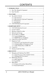
...Wired for Management, remote wake-up, and OnNow initiative to -use interface which provides more control and protection over the motherboard. ASUS CUSI-M User's Manual 9 FEATURES Optional Components 2. Provides Vcore and CPU/ SDRAM frequency adjustments, boot block write protection, and HD/SCSI... ZIP/CD/Floppy boot selection. FEATURES • Enhanced ACPI & Anti-Boot Virus Protection: Programmable BIOS (Flash EEPROM), offering enhanced ACPI for virtually automatic setup. • Smart BIOS: 2Mbit flash ROM gives a new easy-to reduce Total Cost of Ownership (TCO). 2.1.2 Specifications-...
...Wired for Management, remote wake-up, and OnNow initiative to -use interface which provides more control and protection over the motherboard. ASUS CUSI-M User's Manual 9 FEATURES Optional Components 2. Provides Vcore and CPU/ SDRAM frequency adjustments, boot block write protection, and HD/SCSI... ZIP/CD/Floppy boot selection. FEATURES • Enhanced ACPI & Anti-Boot Virus Protection: Programmable BIOS (Flash EEPROM), offering enhanced ACPI for virtually automatic setup. • Smart BIOS: 2Mbit flash ROM gives a new easy-to reduce Total Cost of Ownership (TCO). 2.1.2 Specifications-...
CUSI-M User Manual
Page 10
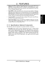
... systems and components are based on all system components, and 32-bit device drivers and installation procedures for configuring and managing all ASUS smart series motherboards. FEATURES Performance 2. This motherboard with existing DMA devices and systems so there is also implemented on the following high... UltraDMA/33 Bus Master IDE can be used. • New Compliancy: Both the BIOS and hardware levels of ACPI, an ACPI-supported OS, such as required by PC 99. 10 ASUS CUSI-M User's Manual To fully utilize the benefits of the motherboard meet the stringent requirements for...
... systems and components are based on all system components, and 32-bit device drivers and installation procedures for configuring and managing all ASUS smart series motherboards. FEATURES Performance 2. This motherboard with existing DMA devices and systems so there is also implemented on the following high... UltraDMA/33 Bus Master IDE can be used. • New Compliancy: Both the BIOS and hardware levels of ACPI, an ACPI-supported OS, such as required by PC 99. 10 ASUS CUSI-M User's Manual To fully utilize the benefits of the motherboard meet the stringent requirements for...

CUSI-M User Manual
Page 11
...Through BIOS, the power button can be powered ON using your keyboard. All the fans are monitored to ensure stable current to prevent possible application crashes. This function requires ACPI OS and driver support. • Peripheral Power Up: Keyboard power up to critical motherboard components. ASUS CUSI-M...applications. Regardless of the setting, pushing the power button for more memory and hard drive space to be turned on remotely through BIOS setup to allow the computer to the user. A simple glimpse provides useful information to be monitored for its normal RPM range ...
...Through BIOS, the power button can be powered ON using your keyboard. All the fans are monitored to ensure stable current to prevent possible application crashes. This function requires ACPI OS and driver support. • Peripheral Power Up: Keyboard power up to critical motherboard components. ASUS CUSI-M...applications. Regardless of the setting, pushing the power button for more memory and hard drive space to be turned on remotely through BIOS setup to allow the computer to the user. A simple glimpse provides useful information to be monitored for its normal RPM range ...
CUSI-M User Manual
Page 12
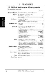
FEATURES 2.2 CUSI-M Motherboard Components See opposite page for Pentium III/Celeron Processors 2 Chipsets SiS 630E 3C Integration Single Chip 3 ITE 8705 Super I/O Chipset 14 2Mbit Flash BIOS 13 Main Memory Maximum 1GB support 2 DIMM Sockets 4 PC100/133 SDRAM and VCM SDRAM support... Top) 22 Wake-On-LAN Connector 10 Wake-On-Ring Connector 1 Other Features ASUS iPanel Connector 9 ASUS iPanel Audio Connector 18 Power ATX Power Supply Connector 5 Form Factor microATX 12 ASUS CUSI-M User's Manual 2. Location Processor Support Socket 370 for locations. FEATURES MB Components ...
FEATURES 2.2 CUSI-M Motherboard Components See opposite page for Pentium III/Celeron Processors 2 Chipsets SiS 630E 3C Integration Single Chip 3 ITE 8705 Super I/O Chipset 14 2Mbit Flash BIOS 13 Main Memory Maximum 1GB support 2 DIMM Sockets 4 PC100/133 SDRAM and VCM SDRAM support... Top) 22 Wake-On-LAN Connector 10 Wake-On-Ring Connector 1 Other Features ASUS iPanel Connector 9 ASUS iPanel Audio Connector 18 Power ATX Power Supply Connector 5 Form Factor microATX 12 ASUS CUSI-M User's Manual 2. Location Processor Support Socket 370 for locations. FEATURES MB Components ...
CUSI-M User Manual
Page 14
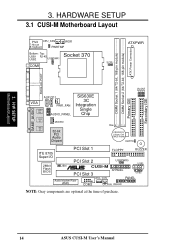
H/W SETUP Motherboard Layout 3. HARDWARE SETUP 3.1 CUSI-M Motherboard Layout 01 PS/2 CPU_FAN WOR T: Mouse B: Keyboard PWRTMP Bottom: Top: USB1 RJ-45 Socket 370 USB2 USBPWR1 COM1 ATXPWR SCPU ATX Power Connector DIMM ... CLRTC Primary IDE PCI Slot 1 FLOPPY BUZZER ITE 8705 Super I/O 2Mbit Flash BIOS PCI Slot 2 USBPWR0 USB1 JEN ® CUSI-M PCI Slot 3 AFPANEL USB2 Audio Modem Riser (AMR) WOL_CON PANEL COM2 CH_FAN IDELED NOTE: Gray components are optional at the time of purchase. 14 ASUS CUSI-M User's Manual JP3 JP1 JP2 Secondary IDE JP0 3.
H/W SETUP Motherboard Layout 3. HARDWARE SETUP 3.1 CUSI-M Motherboard Layout 01 PS/2 CPU_FAN WOR T: Mouse B: Keyboard PWRTMP Bottom: Top: USB1 RJ-45 Socket 370 USB2 USBPWR1 COM1 ATXPWR SCPU ATX Power Connector DIMM ... CLRTC Primary IDE PCI Slot 1 FLOPPY BUZZER ITE 8705 Super I/O 2Mbit Flash BIOS PCI Slot 2 USBPWR0 USB1 JEN ® CUSI-M PCI Slot 3 AFPANEL USB2 Audio Modem Riser (AMR) WOL_CON PANEL COM2 CH_FAN IDELED NOTE: Gray components are optional at the time of purchase. 14 ASUS CUSI-M User's Manual JP3 JP1 JP2 Secondary IDE JP0 3.
CUSI-M User Manual
Page 16
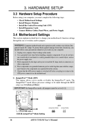
... supply case. 3. H/W SETUP Motherboard Settings 01 JP3 JP1 JP2 JP0 3 2 1 ® CUSI-M CUSI-M JumperFree™ Mode Setting JEN Jumperless Mode Jumper Mode 12 12 16 ASUS CUSI-M User's Manual Ensure that came with the component whenever the components are separated from static electricity, ...on the bag that the ATX power supply is switched off before handling computer components. Unplug your motherboard's function settings through the BIOS setup (see 4.4 Advanced Menu) IMPORTANT: In JumperFree mode, all jumpers must complete the following steps: • Check Motherboard ...
... supply case. 3. H/W SETUP Motherboard Settings 01 JP3 JP1 JP2 JP0 3 2 1 ® CUSI-M CUSI-M JumperFree™ Mode Setting JEN Jumperless Mode Jumper Mode 12 12 16 ASUS CUSI-M User's Manual Ensure that came with the component whenever the components are separated from static electricity, ...on the bag that the ATX power supply is switched off before handling computer components. Unplug your motherboard's function settings through the BIOS setup (see 4.4 Advanced Menu) IMPORTANT: In JumperFree mode, all jumpers must complete the following steps: • Check Motherboard ...
CUSI-M User Manual
Page 20
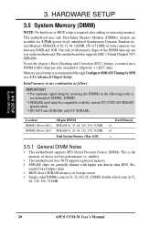
... SDRAM memory on the motherboard. double-sided come in 32, 64, 128, 256, 512MB. 20 ASUS CUSI-M User's Manual HARDWARE SETUP 3.5 System Memory (DIMM) NOTE: No hardware or BIOS setup is recommended through Configure SDRAM Timing by SPD (see 4.4.2 Advanced Chipset Setup). to form a memory size between 16MB and 1GB. One side (with...
... SDRAM memory on the motherboard. double-sided come in 32, 64, 128, 256, 512MB. 20 ASUS CUSI-M User's Manual HARDWARE SETUP 3.5 System Memory (DIMM) NOTE: No hardware or BIOS setup is recommended through Configure SDRAM Timing by SPD (see 4.4.2 Advanced Chipset Setup). to form a memory size between 16MB and 1GB. One side (with...
CUSI-M User Manual
Page 23
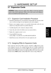
... 4 IRQs free. 3. 3. If your motherboard also has MIDI enabled, another IRQ will be used . Replace the computer system's cover. 6. Set up the BIOS if necessary (such as jumpers. 2. In a standard design, there are 16 IRQs available but most of them are already in PNP AND PCI SETUP) 7. ...Failure to do so may cause severe damage to one use . Secure the card on the slot you removed above. 5. H/W SETUP Expansion Cards ASUS CUSI-M User's Manual 23 Keep the bracket for possible future use , leaving 6 IRQs free for your power supply when adding or removing expansion cards or...
... 4 IRQs free. 3. 3. If your motherboard also has MIDI enabled, another IRQ will be used . Replace the computer system's cover. 6. Set up the BIOS if necessary (such as jumpers. 2. In a standard design, there are 16 IRQs available but most of them are already in PNP AND PCI SETUP) 7. ...Failure to do so may cause severe damage to one use . Secure the card on the slot you removed above. 5. H/W SETUP Expansion Cards ASUS CUSI-M User's Manual 23 Keep the bracket for possible future use , leaving 6 IRQs free for your power supply when adding or removing expansion cards or...
CUSI-M User Manual
Page 30
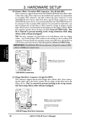
... NOTE: Orient the red markings on the other end to the floppy drives. (Pin 5 is removed to PIN 1. ® CUSI-M PIN 1 CUSI-M Floppy Disk Drive Connector 30 ASUS CUSI-M User's Manual HARDWARE SETUP 10) Primary (Blue) / Secondary IDE Connectors (Two 40-1pin IDE) These connectors support the provided ... the wrong orientation when using ribbon cables with pin 20 plugged). tion when using ribbon cables with pin 5 plugged). 01 01 3. BIOS now supports specific device bootup (see 4.4.1 Advanced CMOS Setup). (Pin 20 is recommended that non-UltraDMA/66 devices be both Masters with...
... NOTE: Orient the red markings on the other end to the floppy drives. (Pin 5 is removed to PIN 1. ® CUSI-M PIN 1 CUSI-M Floppy Disk Drive Connector 30 ASUS CUSI-M User's Manual HARDWARE SETUP 10) Primary (Blue) / Secondary IDE Connectors (Two 40-1pin IDE) These connectors support the provided ... the wrong orientation when using ribbon cables with pin 20 plugged). tion when using ribbon cables with pin 5 plugged). 01 01 3. BIOS now supports specific device bootup (see 4.4.1 Advanced CMOS Setup). (Pin 20 is recommended that non-UltraDMA/66 devices be both Masters with...
CUSI-M User Manual
Page 39
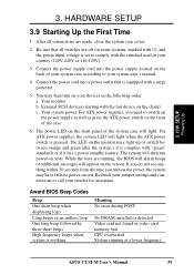
... error during POST No DRAM installed or detected Video card not found or video card memory bad CPU overheated System running , the BIOS will alarm beeps or additional messages will appear on the front of the system case will light when the ATX power switch is ... your system user's manual. 4. Award BIOS Beep Codes Beep One short beep when displaying logo Long beeps in some systems, marked with a surge protector. 5. Your monitor b. Your system power. The power LED on tests. 3. After all switches are running at a lower frequency ASUS CUSI-M User's Manual 39 H/W SETUP Powering ...
... error during POST No DRAM installed or detected Video card not found or video card memory bad CPU overheated System running , the BIOS will alarm beeps or additional messages will appear on the front of the system case will light when the ATX power switch is ... your system user's manual. 4. Award BIOS Beep Codes Beep One short beep when displaying logo Long beeps in some systems, marked with a surge protector. 5. Your monitor b. Your system power. The power LED on tests. 3. After all switches are running at a lower frequency ASUS CUSI-M User's Manual 39 H/W SETUP Powering ...
CUSI-M User Manual
Page 40
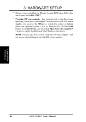
BIOS SETUP. * Powering Off your computer: You must first exit or shut down your computer" will not appear when shutting down with ATX power supplies. 3. If ... . Follow the instructions in 4. NOTE: The message "You can press the ATX power switch after Windows shuts down your operating system. H/W SETUP Powering Up 40 ASUS CUSI-M User's Manual 3. For ATX power supplies, you use Windows 9X, click the Start button, click Shut Down, and then click Shut down to enter...
BIOS SETUP. * Powering Off your computer: You must first exit or shut down your computer" will not appear when shutting down with ATX power supplies. 3. If ... . Follow the instructions in 4. NOTE: The message "You can press the ATX power switch after Windows shuts down your operating system. H/W SETUP Powering Up 40 ASUS CUSI-M User's Manual 3. For ATX power supplies, you use Windows 9X, click the Start button, click Shut Down, and then click Shut down to enter...
CUSI-M User Manual
Page 41
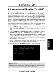
... copy AUTOEXEC.BAT & CONFIG.SYS to create a bootable system floppy disk. ASUS CUSI-M User's Manual 41 Larger numbers represent a newer BIOS file. 1. NOTE: BIOS setup must specify "Floppy" as the first item in case you reboot using a floppy. 3. BIOS SETUP 4.1 Managing and Updating Your BIOS 4.1.1 Upon First Use of the Computer System It is recommended that...
... copy AUTOEXEC.BAT & CONFIG.SYS to create a bootable system floppy disk. ASUS CUSI-M User's Manual 41 Larger numbers represent a newer BIOS file. 1. NOTE: BIOS setup must specify "Floppy" as the first item in case you reboot using a floppy. 3. BIOS SETUP 4.1 Managing and Updating Your BIOS 4.1.1 Upon First Use of the Computer System It is recommended that...
CUSI-M User Manual
Page 42
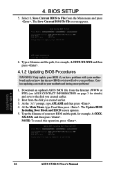
... example, A:\XXXXX.XXX, and then press . Download an updated ASUS BIOS file from the Internet (WWW or FTP) (see ASUS CONTACT INFORMATION on page 3 for details) and save to File from the disk you created earlier. 2. BIOS SETUP Updating BIOS 42 ASUS CUSI-M User's Manual 4. The Update BIOS Including Boot Block and ESCD screen appears. 5. At the Main...
... example, A:\XXXXX.XXX, and then press . Download an updated ASUS BIOS file from the Internet (WWW or FTP) (see ASUS CONTACT INFORMATION on page 3 for details) and save to File from the disk you created earlier. 2. BIOS SETUP Updating BIOS 42 ASUS CUSI-M User's Manual 4. The Update BIOS Including Boot Block and ESCD screen appears. 5. At the Main...
CUSI-M User Manual
Page 43
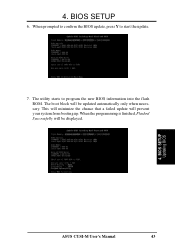
BIOS SETUP Updating BIOS ASUS CUSI-M User's Manual 43 The boot block will be displayed. 4. When prompted to confirm the BIOS update, press Y to program the new BIOS information into the flash ROM. The utility starts to start the update. 7. 4. This will minimize the chance that a failed update will be updated automatically only when necessary. When the programming is finished, Flashed Successfully will prevent your system from booting up. BIOS SETUP 6.
BIOS SETUP Updating BIOS ASUS CUSI-M User's Manual 43 The boot block will be displayed. 4. When prompted to confirm the BIOS update, press Y to program the new BIOS information into the flash ROM. The utility starts to start the update. 7. 4. This will minimize the chance that a failed update will be updated automatically only when necessary. When the programming is finished, Flashed Successfully will prevent your system from booting up. BIOS SETUP 6.
CUSI-M User Manual
Page 44
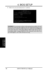
4. Just repeat the process, and if the problem still persists, update the original BIOS file you encounter problems while updating the new BIOS, DO NOT turn off your system since this happens, your system will need servicing. 4. If the Flash Memory Writer utility was not able to successfully update a complete BIOS file, your system from booting up . Follow the onscreen instructions to disk above. If this might prevent your system may not be able to boot up . BIOS SETUP 8. If you saved to continue. BIOS SETUP Updating BIOS 44 ASUS CUSI-M User's Manual WARNING!
4. Just repeat the process, and if the problem still persists, update the original BIOS file you encounter problems while updating the new BIOS, DO NOT turn off your system since this happens, your system will need servicing. 4. If the Flash Memory Writer utility was not able to successfully update a complete BIOS file, your system from booting up . Follow the onscreen instructions to disk above. If this might prevent your system may not be able to boot up . BIOS SETUP 8. If you saved to continue. BIOS SETUP Updating BIOS 44 ASUS CUSI-M User's Manual WARNING!
CUSI-M User Manual
Page 45
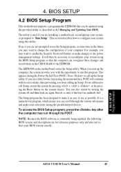
... program, at some time in the CMOS RAM of your system using the BIOS Setup program so that can also restart by pressing the Reset button on the system chassis. 4. BIOS SETUP Program Information ASUS CUSI-M User's Manual 45 If you are a little bit late in 4.1 Managing... and Updating Your BIOS. The Setup program has been designed to make your system using the provided ...
... program, at some time in the CMOS RAM of your system using the BIOS Setup program so that can also restart by pressing the Reset button on the system chassis. 4. BIOS SETUP Program Information ASUS CUSI-M User's Manual 45 If you are a little bit late in 4.1 Managing... and Updating Your BIOS. The Setup program has been designed to make your system using the provided ...
CUSI-M User Manual
Page 46
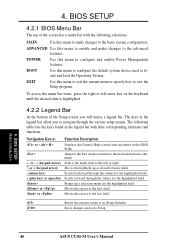
... to the first field or Moves the cursor to the last field Resets the current screen to the advanced features. BIOS SETUP Menu Introduction 46 ASUS CUSI-M User's Manual 4. The following selections: MAIN Use this menu to make changes to its Setup Defaults Saves changes...Scrolls backward through the values for the highlighted field + (plus key) or spacebar Scrolls forward through the various setup menus. BIOS SETUP 4.2.1 BIOS Menu Bar The top of the Setup screen you to the basic system configuration. Navigation Key(s) Function Description or Displays the General...
... to the first field or Moves the cursor to the last field Resets the current screen to the advanced features. BIOS SETUP Menu Introduction 46 ASUS CUSI-M User's Manual 4. The following selections: MAIN Use this menu to make changes to its Setup Defaults Saves changes...Scrolls backward through the values for the highlighted field + (plus key) or spacebar Scrolls forward through the various setup menus. BIOS SETUP 4.2.1 BIOS Menu Bar The top of the Setup screen you to the basic system configuration. Navigation Key(s) Function Description or Displays the General...


