CUSI-M User Manual
Page 1
R CUSI-M Socket 370 microATX Motherboard USER'S MANUAL
R CUSI-M Socket 370 microATX Motherboard USER'S MANUAL

CUSI-M User Manual
Page 2
...in the manual revision number. Manual revisions are used only for each product design represented by ASUS; Manual updates are both printed on the following page. All Rights Reserved. Product Name: ASUS CUSI-M Manual Revision: 1.01 E605 Release Date: September 2000 2 ASUS CUSI-M User's Manual or (2)... the serial number of alteration is defaced or missing. IN NO EVENT SHALL ASUS, ITS DIRECTORS, OFFICERS, EMPLOYEES OR AGENTS BE ...
...in the manual revision number. Manual revisions are used only for each product design represented by ASUS; Manual updates are both printed on the following page. All Rights Reserved. Product Name: ASUS CUSI-M Manual Revision: 1.01 E605 Release Date: September 2000 2 ASUS CUSI-M User's Manual or (2)... the serial number of alteration is defaced or missing. IN NO EVENT SHALL ASUS, ITS DIRECTORS, OFFICERS, EMPLOYEES OR AGENTS BE ...
CUSI-M User Manual
Page 3
...2894-3447 ext. 111 Fax: +886-2-2895-9254 Email: tsd@asus.com.tw Newsgroup: news2.asus.com.tw WWW: www.asus.com.tw FTP: ftp.asus.com.tw/pub/ASUS ASUS COMPUTER INTERNATIONAL (America) Marketing Address: 6737 Mowry Avenue, Mowry Business ...ASUS ASUS COMPUTER GmbH (Europe) Marketing Address: Harkort Str. 25, 40880 Ratingen, BRD, Germany Telephone: 49-2102-445011 Fax: 49-2102-442066 Email: [email protected] Technical Support Hotline: 49-2102-499712 BBS: 49-2102-448690 Email: [email protected] WWW: www.asuscom.de FTP: ftp.asuscom.de/pub/ASUSCOM ASUS CUSI-M User's Manual...
...2894-3447 ext. 111 Fax: +886-2-2895-9254 Email: tsd@asus.com.tw Newsgroup: news2.asus.com.tw WWW: www.asus.com.tw FTP: ftp.asus.com.tw/pub/ASUS ASUS COMPUTER INTERNATIONAL (America) Marketing Address: 6737 Mowry Avenue, Mowry Business ...ASUS ASUS COMPUTER GmbH (Europe) Marketing Address: Harkort Str. 25, 40880 Ratingen, BRD, Germany Telephone: 49-2102-445011 Fax: 49-2102-442066 Email: [email protected] Technical Support Hotline: 49-2102-499712 BBS: 49-2102-448690 Email: [email protected] WWW: www.asuscom.de FTP: ftp.asuscom.de/pub/ASUSCOM ASUS CUSI-M User's Manual...
CUSI-M User Manual
Page 4
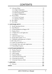
... 4.2 BIOS Setup Program 45 4.2.1 BIOS Menu Bar 46 4.2.2 Legend Bar 46 4.3 Main Menu 48 4.3.1 Primary & Secondary Master/Slave 49 4.3.2 Keyboard Features 52 4 ASUS CUSI-M User's Manual CONTENTS 1. HARDWARE SETUP 14 3.1 CUSI-M Motherboard Layout 14 3.2 Layout Contents 15 3.3 Hardware Setup Procedure 16 3.4 Motherboard Settings 16 3.5 System Memory (DIMM 20 3.5.1 General DIMM Notes 20 3.5.2 DIMM Memory...
... 4.2 BIOS Setup Program 45 4.2.1 BIOS Menu Bar 46 4.2.2 Legend Bar 46 4.3 Main Menu 48 4.3.1 Primary & Secondary Master/Slave 49 4.3.2 Keyboard Features 52 4 ASUS CUSI-M User's Manual CONTENTS 1. HARDWARE SETUP 14 3.1 CUSI-M Motherboard Layout 14 3.2 Layout Contents 15 3.3 Hardware Setup Procedure 16 3.4 Motherboard Settings 16 3.5 System Memory (DIMM 20 3.5.1 General DIMM Notes 20 3.5.2 DIMM Memory...
CUSI-M User Manual
Page 5
... 83 5.11 Adobe Acrobat Reader Vx.x 84 5.12 Cyberlink Video and Audio Applications 85 5.13 Uninstalling Programs 86 6. APPENDIX 105 7.1 Glossary 105 INDEX 109 ASUS CUSI-M User's Manual 5 SOFTWARE REFERENCE 89 6.1 Display Properties 89 6.2 ASUS PC Probe 93 6.3 ASUS Update 98 6.4 Yamaha XGPlayer 99 6.5 CyberLink PowerPlayer SE 100 6.6 CyberLink PowerDVD 101 6.7 CyberLink VideoLive Mail 102 7.
... 83 5.11 Adobe Acrobat Reader Vx.x 84 5.12 Cyberlink Video and Audio Applications 85 5.13 Uninstalling Programs 86 6. APPENDIX 105 7.1 Glossary 105 INDEX 109 ASUS CUSI-M User's Manual 5 SOFTWARE REFERENCE 89 6.1 Display Properties 89 6.2 ASUS PC Probe 93 6.3 ASUS Update 98 6.4 Yamaha XGPlayer 99 6.5 CyberLink PowerPlayer SE 100 6.6 CyberLink PowerDVD 101 6.7 CyberLink VideoLive Mail 102 7.
CUSI-M User Manual
Page 6
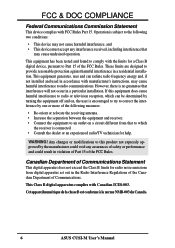
.... These limits are designed to radio communications. Cet appareil numérique de la classe B est conforme à la norme NMB-003 du Canada. 6 ASUS CUSI-M User's Manual WARNING! Canadian Department of Communications Statement This digital apparatus does not exceed the Class B limits for help. Operation is connected. • Consult the dealer or...
.... These limits are designed to radio communications. Cet appareil numérique de la classe B est conforme à la norme NMB-003 du Canada. 6 ASUS CUSI-M User's Manual WARNING! Canadian Department of Communications Statement This digital apparatus does not exceed the Class B limits for help. Operation is connected. • Consult the dealer or...

CUSI-M User Manual
Page 7
... connector set with bracket (1) I/O Shield (1) Bag of spare jumpers (1) Support drivers and utilities (1) This Motherboard User's Manual Optional Items ASUS consumer infrared set Modem riser ASUS CUSI-M User's Manual 7 INTRODUCTION 2. SOFTWARE SETUP 6. INTRODUCTION Manual / Checklist 1. SOFTWARE REFERENCE 7. Package Contents (1) ASUS Motherboard (1) 40-pin 80-conductor ribbon cable for internal UltraDMA/ 66 or UltraDMA/33 IDE drives (1) Ribbon...
... connector set with bracket (1) I/O Shield (1) Bag of spare jumpers (1) Support drivers and utilities (1) This Motherboard User's Manual Optional Items ASUS consumer infrared set Modem riser ASUS CUSI-M User's Manual 7 INTRODUCTION 2. SOFTWARE SETUP 6. INTRODUCTION Manual / Checklist 1. SOFTWARE REFERENCE 7. Package Contents (1) ASUS Motherboard (1) 40-pin 80-conductor ribbon cable for internal UltraDMA/ 66 or UltraDMA/33 IDE drives (1) Ribbon...
CUSI-M User Manual
Page 8
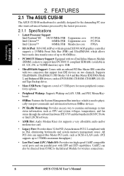
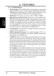
... • Legacy Free: Provides three 32-bit PCI (Asynchronous PCI 2.2 compliant) with EPP and ECP capabilities. FEATURES 2.1 The ASUS CUSI-M The ASUS CUSI-M motherboard is carefully designed for the demanding PC user who wants advanced features processed by the fastest processors. 2.1.1 Specifications • ...: Features the System Management Bus interface, which allows burst mode data transfer rates of 5 USB ports for wireless connections. 8 ASUS CUSI-M User's Manual UART2 can support Bus Master PCI cards, such as SCSI or LAN cards. (PCI supports up to the Infrared Module for ...
... • Legacy Free: Provides three 32-bit PCI (Asynchronous PCI 2.2 compliant) with EPP and ECP capabilities. FEATURES 2.1 The ASUS CUSI-M The ASUS CUSI-M motherboard is carefully designed for the demanding PC user who wants advanced features processed by the fastest processors. 2.1.1 Specifications • ...: Features the System Management Bus interface, which allows burst mode data transfer rates of 5 USB ports for wireless connections. 8 ASUS CUSI-M User's Manual UART2 can support Bus Master PCI cards, such as SCSI or LAN cards. (PCI supports up to the Infrared Module for ...
CUSI-M User Manual
Page 9
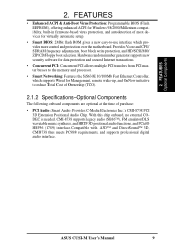
ASUS CUSI-M User's Manual 9 Hardware random number generator supports new security software for data protection and secured Internet transactions. • Concurrent PCI: Concurrent PCI allows multiple PCI transfers from ...
ASUS CUSI-M User's Manual 9 Hardware random number generator supports new security software for data protection and secured Internet transactions. • Concurrent PCI: Concurrent PCI allows multiple PCI transfers from ...
CUSI-M User Manual
Page 10
... can be used. • New Compliancy: Both the BIOS and hardware levels of ACPI, an ACPI-supported OS, such as required by PC 99. 10 ASUS CUSI-M User's Manual With these features implemented in two channels. The new PC 99 requirements for systems and components are based on all...
... can be used. • New Compliancy: Both the BIOS and hardware levels of ACPI, an ACPI-supported OS, such as required by PC 99. 10 ASUS CUSI-M User's Manual With these features implemented in two channels. The new PC 99 requirements for systems and components are based on all...

CUSI-M User Manual
Page 11
...system damage, this benefit on-hand, users can access any information from their computers from anywhere in conjunction with either the bundled ASUS PC Probe or Intel LDCM will give the user information on remotely through BIOS setup to allow the computer to present enormous ...efficiently. • Dual Function Power Button: Through BIOS, the power button can determine if a message has been received from a fax/modem. ASUS CUSI-M User's Manual 11 2. Suggestions will warn the user before the system resources are set for RPM and failure. This function requires ACPI OS and driver support...
...system damage, this benefit on-hand, users can access any information from their computers from anywhere in conjunction with either the bundled ASUS PC Probe or Intel LDCM will give the user information on remotely through BIOS setup to allow the computer to present enormous ...efficiently. • Dual Function Power Button: Through BIOS, the power button can determine if a message has been received from a fax/modem. ASUS CUSI-M User's Manual 11 2. Suggestions will warn the user before the system resources are set for RPM and failure. This function requires ACPI OS and driver support...
CUSI-M User Manual
Page 12
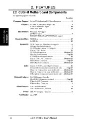
Location Processor Support Socket 370 for locations. 2. FEATURES MB Components 2. FEATURES 2.2 CUSI-M Motherboard Components See opposite page for Pentium III/Celeron Processors 2 Chipsets SiS 630E 3C Integration Single Chip 3 ITE 8705 Super I/O Chipset 14 2Mbit ...... (Bottom) 17 Network Features SiS630E Ethernet Controller 1 LAN (RJ45) Connector (optional Top) 22 Wake-On-LAN Connector 10 Wake-On-Ring Connector 1 Other Features ASUS iPanel Connector 9 ASUS iPanel Audio Connector 18 Power ATX Power Supply Connector 5 Form Factor microATX 12 ASUS CUSI-M User's Manual
Location Processor Support Socket 370 for locations. 2. FEATURES MB Components 2. FEATURES 2.2 CUSI-M Motherboard Components See opposite page for Pentium III/Celeron Processors 2 Chipsets SiS 630E 3C Integration Single Chip 3 ITE 8705 Super I/O Chipset 14 2Mbit ...... (Bottom) 17 Network Features SiS630E Ethernet Controller 1 LAN (RJ45) Connector (optional Top) 22 Wake-On-LAN Connector 10 Wake-On-Ring Connector 1 Other Features ASUS iPanel Connector 9 ASUS iPanel Audio Connector 18 Power ATX Power Supply Connector 5 Form Factor microATX 12 ASUS CUSI-M User's Manual
CUSI-M User Manual
Page 14
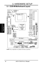
HARDWARE SETUP 3.1 CUSI-M Motherboard Layout 01 PS/2 CPU_FAN WOR T: Mouse B: Keyboard PWRTMP Bottom: Top: USB1 RJ-45 Socket 370 USB2 USBPWR1 COM1 ATXPWR SCPU ATX Power Connector DIMM ... PCI Slot 1 FLOPPY BUZZER ITE 8705 Super I/O 2Mbit Flash BIOS PCI Slot 2 USBPWR0 USB1 JEN ® CUSI-M PCI Slot 3 AFPANEL USB2 Audio Modem Riser (AMR) WOL_CON PANEL COM2 CH_FAN IDELED NOTE: Gray components are optional at the time of purchase. 14 ASUS CUSI-M User's Manual JP3 JP1 JP2 Secondary IDE JP0 3. H/W SETUP Motherboard Layout 3.
HARDWARE SETUP 3.1 CUSI-M Motherboard Layout 01 PS/2 CPU_FAN WOR T: Mouse B: Keyboard PWRTMP Bottom: Top: USB1 RJ-45 Socket 370 USB2 USBPWR1 COM1 ATXPWR SCPU ATX Power Connector DIMM ... PCI Slot 1 FLOPPY BUZZER ITE 8705 Super I/O 2Mbit Flash BIOS PCI Slot 2 USBPWR0 USB1 JEN ® CUSI-M PCI Slot 3 AFPANEL USB2 Audio Modem Riser (AMR) WOL_CON PANEL COM2 CH_FAN IDELED NOTE: Gray components are optional at the time of purchase. 14 ASUS CUSI-M User's Manual JP3 JP1 JP2 Secondary IDE JP0 3. H/W SETUP Motherboard Layout 3.

CUSI-M User Manual
Page 15
... p.33 USB Connector Set (10-1 pins, 5-1 pins) 17) CD1, AUX, MODEM p.34 Internal Audio Connectors (Two 4 pins) (optional) 18) AFPANEL p.35 ASUS iPanel Connector (12-1 pins) 19) AAPANEL p.35 ASUS iPanel Audio Connector (12-1 pins) 20) SPEAKER (PANEL) p.37 System Warning Speaker Connector (4 pins) 21) KLOCK (PANEL) p.37 Keyboard Lock Switch Lead...) RESET (PANEL) p.37 Reset Switch Lead (2 pins) 27) ATXPWR p.38 ATX Power Supply Connector (20 pins) 28) PWRTMP p.38 Power Supply Thermal Sensor Connector (2 pins) ASUS CUSI-M User's Manual 15 3. H/W SETUP Layout Contents 3.
... p.33 USB Connector Set (10-1 pins, 5-1 pins) 17) CD1, AUX, MODEM p.34 Internal Audio Connectors (Two 4 pins) (optional) 18) AFPANEL p.35 ASUS iPanel Connector (12-1 pins) 19) AAPANEL p.35 ASUS iPanel Audio Connector (12-1 pins) 20) SPEAKER (PANEL) p.37 System Warning Speaker Connector (4 pins) 21) KLOCK (PANEL) p.37 Keyboard Lock Switch Lead...) RESET (PANEL) p.37 Reset Switch Lead (2 pins) 27) ATXPWR p.38 ATX Power Supply Connector (20 pins) 28) PWRTMP p.38 Power Supply Thermal Sensor Connector (2 pins) ASUS CUSI-M User's Manual 15 3. H/W SETUP Layout Contents 3.
CUSI-M User Manual
Page 16
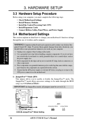
... not to enable or disable the JumperFree™ mode. H/W SETUP Motherboard Settings 01 JP3 JP1 JP2 JP0 3 2 1 ® CUSI-M CUSI-M JumperFree™ Mode Setting JEN Jumperless Mode Jumper Mode 12 12 16 ASUS CUSI-M User's Manual Place components on a grounded antistatic pad or on your computer, you do not have one, touch both of switches...
... not to enable or disable the JumperFree™ mode. H/W SETUP Motherboard Settings 01 JP3 JP1 JP2 JP0 3 2 1 ® CUSI-M CUSI-M JumperFree™ Mode Setting JEN Jumperless Mode Jumper Mode 12 12 16 ASUS CUSI-M User's Manual Place components on a grounded antistatic pad or on your computer, you do not have one, touch both of switches...

CUSI-M User Manual
Page 17
NOTES: 1. H/W SETUP Motherboard Settings ASUS CUSI-M User's Manual 17 HARDWARE SETUP 2) USB Device Wake Up (USBPWR0, USBPWR1) These jumpers allow you set these to Disable because not all computers have the appropriate ATX.... The default is , either both must be set in 4.5.1 Power Up Control. Setting USBPWR0/USBPWR1 Enable [1-2] (default) Disable [2-3] 01 USBPWR1 2 1 Enable 3 2 Disable (Default) ® CUSI-M CUSI-M USB Device Wake Up USBPWR0 12 23 Enable Disable (Default) 3. These settings must be set to Enable and do not have the appropriate ATX power...
NOTES: 1. H/W SETUP Motherboard Settings ASUS CUSI-M User's Manual 17 HARDWARE SETUP 2) USB Device Wake Up (USBPWR0, USBPWR1) These jumpers allow you set these to Disable because not all computers have the appropriate ATX.... The default is , either both must be set in 4.5.1 Power Up Control. Setting USBPWR0/USBPWR1 Enable [1-2] (default) Disable [2-3] 01 USBPWR1 2 1 Enable 3 2 Disable (Default) ® CUSI-M CUSI-M USB Device Wake Up USBPWR0 12 23 Enable Disable (Default) 3. These settings must be set to Enable and do not have the appropriate ATX power...
CUSI-M User Manual
Page 18
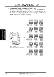
....5MHz 133.3MHz 133.3MHz 33.3MHz 66.8MHz 66.8MHz 33.4MHz JP2 JP1 JP3 JP0 JP2 JP1 JP3 JP0 JP2 JP1 JP3 ® CUSI-M CUSI-M CPU External Frequency Selection 3 2 1 CPU SDRAM PCI 97.0MHz 97.0MHz 32.3MHz 70.0MHz 105.0MHz 35.0MHz 95.0MHz 95.0MHz 31.7MHz....0MHz SDRAM 126.7MHz PCI 31.7MHz 112.0MHz 112.0MHz 37.3MHz 97.0MHz 129.3MHz 32.2MHz JP0 JP0 3. H/W SETUP Motherboard Settings 18 ASUS CUSI-M User's Manual 3. HARDWARE SETUP 3) CPU External Frequency Setting (JP3, JP1, JP2, JP0) This option tells the clock generator what frequency to send to the CPU, SDRAM...
....5MHz 133.3MHz 133.3MHz 33.3MHz 66.8MHz 66.8MHz 33.4MHz JP2 JP1 JP3 JP0 JP2 JP1 JP3 JP0 JP2 JP1 JP3 ® CUSI-M CUSI-M CPU External Frequency Selection 3 2 1 CPU SDRAM PCI 97.0MHz 97.0MHz 32.3MHz 70.0MHz 105.0MHz 35.0MHz 95.0MHz 95.0MHz 31.7MHz....0MHz SDRAM 126.7MHz PCI 31.7MHz 112.0MHz 112.0MHz 37.3MHz 97.0MHz 129.3MHz 32.2MHz JP0 JP0 3. H/W SETUP Motherboard Settings 18 ASUS CUSI-M User's Manual 3. HARDWARE SETUP 3) CPU External Frequency Setting (JP3, JP1, JP2, JP0) This option tells the clock generator what frequency to send to the CPU, SDRAM...
CUSI-M User Manual
Page 19
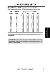
WARNING! H/W SETUP Motherboard Settings ASUS CUSI-M User's Manual 19 HARDWARE SETUP Manual CPU Settings (NOTE: JumperFree mode ... [1-2] [1-2] [2-3] [1-2] [2-3] [1-2] [1-2] [2-3] [2-3] [1-2] [2-3] [2-3] [1-2] [1-2] [2-3] [2-3] [2-3] [2-3] [1-2] [1-2] [1-2] [2-3] [1-2] [1-2] [2-3] [2-3] [2-3] [1-2] [1-2] [2-3] [2-3] [1-2] [2-3] [2-3] [1-2] [2-3] [1-2] [2-3] [1-2] [2-3] [2-3] [2-3] [2-3] [2-3] [1-2] [2-3] [2-3] [2-3] [2-3] For updated processor settings, visit ASUS's web site (see ASUS CONTACT INFORMATION). Be sure that the DIMM you use can handle the specified SDRAM MHz or else bootup...
WARNING! H/W SETUP Motherboard Settings ASUS CUSI-M User's Manual 19 HARDWARE SETUP Manual CPU Settings (NOTE: JumperFree mode ... [1-2] [1-2] [2-3] [1-2] [2-3] [1-2] [1-2] [2-3] [2-3] [1-2] [2-3] [2-3] [1-2] [1-2] [2-3] [2-3] [2-3] [2-3] [1-2] [1-2] [1-2] [2-3] [1-2] [1-2] [2-3] [2-3] [2-3] [1-2] [1-2] [2-3] [2-3] [1-2] [2-3] [2-3] [1-2] [2-3] [1-2] [2-3] [1-2] [2-3] [2-3] [2-3] [2-3] [2-3] [1-2] [2-3] [2-3] [2-3] [2-3] For updated processor settings, visit ASUS's web site (see ASUS CONTACT INFORMATION). Be sure that the DIMM you use can handle the specified SDRAM MHz or else bootup...
CUSI-M User Manual
Page 20
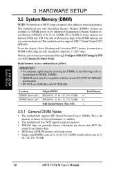
... Memory 3. Install memory in any combination as follows: IMPORTANT • For optimum signal integrity, inserting the DIMMs in 32, 64, 128, 256, 512MB. 20 ASUS CUSI-M User's Manual tended Data Output) chips. • BIOS shows SDRAM memory on bootup screen. • Single-sided DIMMs come in the following order is recommended: DIMM1, DIMM2...
... Memory 3. Install memory in any combination as follows: IMPORTANT • For optimum signal integrity, inserting the DIMMs in 32, 64, 128, 256, 512MB. 20 ASUS CUSI-M User's Manual tended Data Output) chips. • BIOS shows SDRAM memory on bootup screen. • Single-sided DIMMs come in the following order is recommended: DIMM1, DIMM2...

CUSI-M User Manual
Page 21
... identify the type and also to prevent the wrong type from being inserted into the DIMM slot on both sides. Lock 88 Pins 01 ® CUSI-M CUSI-M 168-Pin DIMM Sockets 60 Pins 20 Pins The DIMMs must ask your retailer the correct DIMM type before purchasing. H/W SETUP System Memory DRAM Key... contact on the motherboard. To determine the DIMM type, check the notches on the DIMMs (see figure below). 168-Pin DIMM Notch Key Definitions (3.3V) 3. 3. ASUS CUSI-M User's Manual 21
... identify the type and also to prevent the wrong type from being inserted into the DIMM slot on both sides. Lock 88 Pins 01 ® CUSI-M CUSI-M 168-Pin DIMM Sockets 60 Pins 20 Pins The DIMMs must ask your retailer the correct DIMM type before purchasing. H/W SETUP System Memory DRAM Key... contact on the motherboard. To determine the DIMM type, check the notches on the DIMMs (see figure below). 168-Pin DIMM Notch Key Definitions (3.3V) 3. 3. ASUS CUSI-M User's Manual 21


