CUPLE-VM User Manual
Page 1
® CUPLE-VM JumperFree™ PC133/VC133 133/100/66 MHz FSB Socket 370 Motherboard USER'S MANUAL
® CUPLE-VM JumperFree™ PC133/VC133 133/100/66 MHz FSB Socket 370 Motherboard USER'S MANUAL

CUPLE-VM User Manual
Page 4
... Is Organized 7 1.2 Item Checklist 7 2. CONTENTS 1. FEATURES 8 2.1 The ASUS CUPLE-VM 8 2.1.1 Specifications 8 2.1.2 Special Features 10 2.1.3 Performance Features 10 2.1.4 Intelligence 11 2.2 Motherboard Components 12 2.2.1 Component Locations 13 3. BIOS SETUP 37 4.1 Managing and Updating Your... Program 40 4.2.1 BIOS Menu Bar 41 4.2.2 Legend Bar 41 4 ASUS CUPLE-VM User's Manual HARDWARE SETUP 14 3.1 Motherboard Layout 14 3.2 Layout Contents 15 3.3 Hardware Setup Procedure 16 3.4 Motherboard Settings 16 3.5 System Memory (DIMM 18 3.5.1 General DIMM Notes 18...
... Is Organized 7 1.2 Item Checklist 7 2. CONTENTS 1. FEATURES 8 2.1 The ASUS CUPLE-VM 8 2.1.1 Specifications 8 2.1.2 Special Features 10 2.1.3 Performance Features 10 2.1.4 Intelligence 11 2.2 Motherboard Components 12 2.2.1 Component Locations 13 3. BIOS SETUP 37 4.1 Managing and Updating Your... Program 40 4.2.1 BIOS Menu Bar 41 4.2.2 Legend Bar 41 4 ASUS CUPLE-VM User's Manual HARDWARE SETUP 14 3.1 Motherboard Layout 14 3.2 Layout Contents 15 3.3 Hardware Setup Procedure 16 3.4 Motherboard Settings 16 3.5 System Memory (DIMM 18 3.5.1 General DIMM Notes 18...

CUPLE-VM User Manual
Page 7
... SOFTWARE REFERENCE 7. APPENDIX Manual information and checklist Production information and specifications Intructions on setting up the motherboard. Intructions on setting up the BIOS Intructions on setting up the included software Reference material for one...ASUS CIDB chassis intrusion detection module ASUS IrDA-compliant infrared module (1) 9-pin COM Cable (1) ASUS 2-port USB Connector Set (1) Bag of spare jumper caps (1) ASUS Support CD with drivers and utilities (1) This Motherboard User's Manual ASUS CUPLE-VM User's Manual 7 Package Contents (1) ASUS Motherboard...
... SOFTWARE REFERENCE 7. APPENDIX Manual information and checklist Production information and specifications Intructions on setting up the motherboard. Intructions on setting up the BIOS Intructions on setting up the included software Reference material for one...ASUS CIDB chassis intrusion detection module ASUS IrDA-compliant infrared module (1) 9-pin COM Cable (1) ASUS 2-port USB Connector Set (1) Bag of spare jumper caps (1) ASUS Support CD with drivers and utilities (1) This Motherboard User's Manual ASUS CUPLE-VM User's Manual 7 Package Contents (1) ASUS Motherboard...

CUPLE-VM User Manual
Page 8
complies with two connectors that supports a WOR connector. 8 ASUS CUPLE-VM User's Manual VC SDRAM is a new DRAM core architecture that dramatically improves the memory system's ability to service, among others, high multimedia...Master IDE controller with 4X, 2X, and 1X AGP modes; 2. AC97 audio; bus interface with support for 4 PCI masters. FEATURES 2.1 The ASUS CUPLE-VM The ASUS CUPLE-VM motherboard is carefully designed for the demanding PC user who wants advanced features processed by the fastest processors. 2.1.1 Specifications • Intel® Celeron™/Coppermine...
complies with two connectors that supports a WOR connector. 8 ASUS CUPLE-VM User's Manual VC SDRAM is a new DRAM core architecture that dramatically improves the memory system's ability to service, among others, high multimedia...Master IDE controller with 4X, 2X, and 1X AGP modes; 2. AC97 audio; bus interface with support for 4 PCI masters. FEATURES 2.1 The ASUS CUPLE-VM The ASUS CUPLE-VM motherboard is carefully designed for the demanding PC user who wants advanced features processed by the fastest processors. 2.1.1 Specifications • Intel® Celeron™/Coppermine...

CUPLE-VM User Manual
Page 9
... provides Vcore and CPU/SDRAM frequency adjustments, boot block write protection, and HD/SCSI/MO/ZIP/CD/Floppy boot selection. ASUS CUPLE-VM User's Manual 9 2. FEATURES Specifications 2. FEATURES • USB: Supports up to 4 USB ports, two on the ...status information, such as CPU and systerm voltages, temperatures, and fan status through the onboard hardware ASUS ASIC and the bundled ASUS PC Probe. • SMBus: Features the System Management Bus interface, which is used to ...Flash EEPROM), offering enhanced ACPI for Windows 98 compatibility, built-in this motherboard are color-coded.
... provides Vcore and CPU/SDRAM frequency adjustments, boot block write protection, and HD/SCSI/MO/ZIP/CD/Floppy boot selection. ASUS CUPLE-VM User's Manual 9 2. FEATURES Specifications 2. FEATURES • USB: Supports up to 4 USB ports, two on the ...status information, such as CPU and systerm voltages, temperatures, and fan status through the onboard hardware ASUS ASIC and the bundled ASUS PC Probe. • SMBus: Features the System Management Bus interface, which is used to ...Flash EEPROM), offering enhanced ACPI for Windows 98 compatibility, built-in this motherboard are color-coded.
CUPLE-VM User Manual
Page 10
...%. With these features implemented in the OS, PCs can be enabled.) • VCM/SDRAM Optimized Performance: This motherboard supports a new generation memory, NEC's 64Mb Virtual Channel Memory (VCM) Synchronous Dynamic Random Access Memory (SDRAM), ...Performance 2. UltraDMA/100 is compatible to 50% higher SDRAM speed at reduced power consumption of this motherboard meet the stringent requirements for PC 99 certification The new PC 99 requirements for systems and components are... Data Transfer Interface: IDE transfers using PC100-compliant SDRAMs). 10 ASUS CUPLE-VM User's Manual
...%. With these features implemented in the OS, PCs can be enabled.) • VCM/SDRAM Optimized Performance: This motherboard supports a new generation memory, NEC's 64Mb Virtual Channel Memory (VCM) Synchronous Dynamic Random Access Memory (SDRAM), ...Performance 2. UltraDMA/100 is compatible to 50% higher SDRAM speed at reduced power consumption of this motherboard meet the stringent requirements for PC 99 certification The new PC 99 requirements for systems and components are... Data Transfer Interface: IDE transfers using PC100-compliant SDRAMs). 10 ASUS CUPLE-VM User's Manual

CUPLE-VM User Manual
Page 11
...requires modem): This allows a computer to prevent possible application crashes. Voltage specifications are monitored to ensure stable voltage to critical motherboard components. ASUS CUPLE-VM User's Manual 11 Suggestions will power off mode regardless of two states: sleep mode or soft-off mode, depending on managing...the system is necessary to present enormous user interfaces and run large applications. When the power button is monitored by the ASUS ASIC to prevent system overheat and system damage. • Voltage Monitoring and Alert: System voltage levels are more memory ...
...requires modem): This allows a computer to prevent possible application crashes. Voltage specifications are monitored to ensure stable voltage to critical motherboard components. ASUS CUPLE-VM User's Manual 11 Suggestions will power off mode regardless of two states: sleep mode or soft-off mode, depending on managing...the system is necessary to present enormous user interfaces and run large applications. When the power button is monitored by the ASUS ASIC to prevent system overheat and system damage. • Voltage Monitoring and Alert: System voltage levels are more memory ...
CUPLE-VM User Manual
Page 12
... See opposite page for Intel® Processors 2 (NOTE: CPU thermal sensor is integrated on the motherboard, located near the center of the CPU heat source, just below the CPU socket) VIA® VT8601A (PLE133) system controller 1...LAN Connector 12 Wake-On-Ring Connector 17 Hardware Monitoring System Voltage Monitoring (integrated in ASUS ASIC) ....... 11 3 Fan Power and Speed Monitoring Connectors Power ATX Power Supply Connector 3 Form Factor Micro ATX 12 ASUS CUPLE-VM User's Manual FEATURES Motherboard Parts 2. Location Processor Support Chipsets Socket 370 for locations.
... See opposite page for Intel® Processors 2 (NOTE: CPU thermal sensor is integrated on the motherboard, located near the center of the CPU heat source, just below the CPU socket) VIA® VT8601A (PLE133) system controller 1...LAN Connector 12 Wake-On-Ring Connector 17 Hardware Monitoring System Voltage Monitoring (integrated in ASUS ASIC) ....... 11 3 Fan Power and Speed Monitoring Connectors Power ATX Power Supply Connector 3 Form Factor Micro ATX 12 ASUS CUPLE-VM User's Manual FEATURES Motherboard Parts 2. Location Processor Support Chipsets Socket 370 for locations.
CUPLE-VM User Manual
Page 13
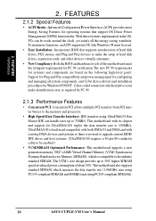
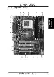
FEATURES 2.2.1 Component Locations 12 3 4 56 24 23 22 21 20 19 18 17 16 15 - 14 13 12 11 10 9 87 ASUS CUPLE-VM User's Manual 13 FEATURES Motherboard Parts 2. 2.
FEATURES 2.2.1 Component Locations 12 3 4 56 24 23 22 21 20 19 18 17 16 15 - 14 13 12 11 10 9 87 ASUS CUPLE-VM User's Manual 13 FEATURES Motherboard Parts 2. 2.
CUPLE-VM User Manual
Page 14
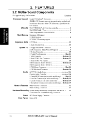
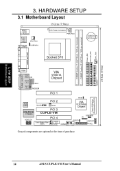
HARDWARE SETUP 3.1 Motherboard Layout 19.2cm (7.56in) PS/2 T: Mouse B: Keyboard Bottom: USB1 USB2 COM1 CPU_FAN USBPWR1 ATX Power Connector PWR_FAN CR2032 3V Lithium Cell CMOS Power Socket 370 ... Codec CHASS PCI 2 WOR CREATIVE CT5880 PCI 3 CUPLE-VM AC97_EN PCI 4 Audio Modem Riser (AMR) ASUS ASIC WOLCON COM2 01 23 R139 VIA VT82C686B Chipset IDELED USBPWR2 IR USBPORT PANEL Grayed components are optional at the time of purchase. Flash EEPROM (Programable BIOS) 14 ASUS CUPLE-VM User's Manual H/W SETUP Motherboard Layout 3. CHA_FAN FLOPPY 24.4cm (9.6in) 3.
HARDWARE SETUP 3.1 Motherboard Layout 19.2cm (7.56in) PS/2 T: Mouse B: Keyboard Bottom: USB1 USB2 COM1 CPU_FAN USBPWR1 ATX Power Connector PWR_FAN CR2032 3V Lithium Cell CMOS Power Socket 370 ... Codec CHASS PCI 2 WOR CREATIVE CT5880 PCI 3 CUPLE-VM AC97_EN PCI 4 Audio Modem Riser (AMR) ASUS ASIC WOLCON COM2 01 23 R139 VIA VT82C686B Chipset IDELED USBPWR2 IR USBPORT PANEL Grayed components are optional at the time of purchase. Flash EEPROM (Programable BIOS) 14 ASUS CUPLE-VM User's Manual H/W SETUP Motherboard Layout 3. CHA_FAN FLOPPY 24.4cm (9.6in) 3.

CUPLE-VM User Manual
Page 15
HARDWARE SETUP 3.2 Layout Contents Motherboard Settings 1) USBPWR1/USBPWR2 p. 17 USB Device Wake-up (Disable/Enable) 2) AC97_EN p. 17 Audio CODEC Setting (Disable/Enable) Expansion Slots/Sockets 1) System Memory p.18 System Memory ...) p.34 System Power LED Lead (3 pin) 21) RESET (PANEL) p.34 Reset Switch Lead (2 pin) 22) PWR.SW (PANEL) p.34 ATX / Soft-Off Switch Lead (2 pin) ASUS CUPLE-VM User's Manual 15 3.
HARDWARE SETUP 3.2 Layout Contents Motherboard Settings 1) USBPWR1/USBPWR2 p. 17 USB Device Wake-up (Disable/Enable) 2) AC97_EN p. 17 Audio CODEC Setting (Disable/Enable) Expansion Slots/Sockets 1) System Memory p.18 System Memory ...) p.34 System Power LED Lead (3 pin) 21) RESET (PANEL) p.34 Reset Switch Lead (2 pin) 22) PWR.SW (PANEL) p.34 ATX / Soft-Off Switch Lead (2 pin) ASUS CUPLE-VM User's Manual 15 3.
CUPLE-VM User Manual
Page 16
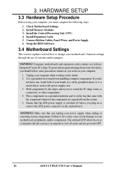
... or remove the ATX power connector on your computer. 1. Install Memory Modules 3. Install the Central Processing Unit (CPU) 4. Computer motherboards and expansion cards contain very delicate Integrated Circuit (IC) chips. Connect Ribbon Cables, Panel Wires, and Power Supply 6. HARDWARE SETUP ..., you plug in suspend or soft-off mode and not powered OFF. 16 ASUS CUPLE-VM User's Manual Place components on a grounded antistatic pad or on the bag that the system is switched off before handling computer components. 3. Check Motherboard Settings 2. Install Expansion Cards 5.
... or remove the ATX power connector on your computer. 1. Install Memory Modules 3. Install the Central Processing Unit (CPU) 4. Computer motherboards and expansion cards contain very delicate Integrated Circuit (IC) chips. Connect Ribbon Cables, Panel Wires, and Power Supply 6. HARDWARE SETUP ..., you plug in suspend or soft-off mode and not powered OFF. 16 ASUS CUPLE-VM User's Manual Place components on a grounded antistatic pad or on the bag that the system is switched off before handling computer components. 3. Check Motherboard Settings 2. Install Expansion Cards 5.

CUPLE-VM User Manual
Page 18
...takes up one row on the motherboard. compliant DIMMs. • ASUS motherboards support SPD (Serial Presence Detect) DIMMs. This is recommended through SDRAM Configuration under "Chipset Features Setup". Be sure that have more ): • SDRAMs used must be possible. 18 ASUS CUPLE-VM User's Manual 3. Install memory... in 32, 64, 128, 256, 512MB. double-sided come in 16, 32, 64,128, 256MB; stability. • BIOS shows SDRAM memory on this motherboard. • For the system CPU bus to...
...takes up one row on the motherboard. compliant DIMMs. • ASUS motherboards support SPD (Serial Presence Detect) DIMMs. This is recommended through SDRAM Configuration under "Chipset Features Setup". Be sure that have more ): • SDRAMs used must be possible. 18 ASUS CUPLE-VM User's Manual 3. Install memory... in 32, 64, 128, 256, 512MB. double-sided come in 16, 32, 64,128, 256MB; stability. • BIOS shows SDRAM memory on this motherboard. • For the system CPU bus to...

CUPLE-VM User Manual
Page 19
...must be 3.3Volt unbuffered SDRAMs. To determine the DIMM type, check the notches on the DIMM will only fit in the orientation shown. ASUS CUPLE-VM User's Manual 19 HARDWARE SETUP 3.5.2 Memory Installation WARNING! Failure to do so may cause severe damage to prevent the wrong type from being ... the correct DIMM type before purchasing. DRAM SIMM modules have a higher pin density. 88 Pins 60 Pins CUPLE-VM 20 Pins CUPLE-VM 168-Pin DIMM Sockets The DIMMs must tell your motherboard and expansion cards (see figure below) 168-Pin DIMM Notch Key Definitions (3.3V) 3. SDRAM DIMMs have ...
...must be 3.3Volt unbuffered SDRAMs. To determine the DIMM type, check the notches on the DIMM will only fit in the orientation shown. ASUS CUPLE-VM User's Manual 19 HARDWARE SETUP 3.5.2 Memory Installation WARNING! Failure to do so may cause severe damage to prevent the wrong type from being ... the correct DIMM type before purchasing. DRAM SIMM modules have a higher pin density. 88 Pins 60 Pins CUPLE-VM 20 Pins CUPLE-VM 168-Pin DIMM Sockets The DIMMs must tell your motherboard and expansion cards (see figure below) 168-Pin DIMM Notch Key Definitions (3.3V) 3. SDRAM DIMMs have ...

CUPLE-VM User Manual
Page 20
... of the CPU with a ZIF Socket for reference only. Be sure that there is working. You may occur to scrape the motherboard when mounting a clampstyle processor fan or else damage may install an auxiliary fan, if necessary. CAUTION! WARNING! It is for.... otherwise, your CPU will be damaged! 20 ASUS CUPLE-VM User's Manual The following illustration shows the CPU socket location on one before installing the CPU. H/W SETUP System Memory 3. HARDWARE SETUP 3.6 Central Processing Unit (CPU) The motherboard comes with the corresponding corner on the socket so...
... of the CPU with a ZIF Socket for reference only. Be sure that there is working. You may occur to scrape the motherboard when mounting a clampstyle processor fan or else damage may install an auxiliary fan, if necessary. CAUTION! WARNING! It is for.... otherwise, your CPU will be damaged! 20 ASUS CUPLE-VM User's Manual The following illustration shows the CPU socket location on one before installing the CPU. H/W SETUP System Memory 3. HARDWARE SETUP 3.6 Central Processing Unit (CPU) The motherboard comes with the corresponding corner on the socket so...

CUPLE-VM User Manual
Page 21
Unlock the socket by the vendor. Do not force the CPU into the socket until it up problems. ASUS CUPLE-VM User's Manual 21 Attach the heatsink and fan to avoid start-up to prevent bending the pins and damaging the CPU. When the CPU is ... fits in place. Locate the ZIF socket on the socket indicating that it firmly on unlocked processors) for bent pins. 5. The lever clicks on the motherboard. 2. HARDWARE SETUP 3.6.1 CPU Installation Follow these steps to the socket. 4. If the CPU does not fit completely, check its notched or marked corner matches the...
Unlock the socket by the vendor. Do not force the CPU into the socket until it up problems. ASUS CUPLE-VM User's Manual 21 Attach the heatsink and fan to avoid start-up to prevent bending the pins and damaging the CPU. When the CPU is ... fits in place. Locate the ZIF socket on the socket indicating that it firmly on unlocked processors) for bent pins. 5. The lever clicks on the motherboard. 2. HARDWARE SETUP 3.6.1 CPU Installation Follow these steps to the socket. 4. If the CPU does not fit completely, check its notched or marked corner matches the...

CUPLE-VM User Manual
Page 22
... the bracket plate on the slot you may cause severe damage to change the settings.) 7. 3. Keep the screw for the expansion card. 22 ASUS CUPLE-VM User's Manual Align the card connectors with the screw you removed earlier. 5. Replace the system cover. 6. Follow the steps in place. 4. .... 2. Read the documentation that comes with the expansion card and make any . (see section 4.4.3 PCI Configuration to both the motherboard and expansion cards. 3.7.1 Installing an Expansion Card 1. HARDWARE SETUP 3.7 Expansion Cards In the future, you intend to support these cards.
... the bracket plate on the slot you may cause severe damage to change the settings.) 7. 3. Keep the screw for the expansion card. 22 ASUS CUPLE-VM User's Manual Align the card connectors with the screw you removed earlier. 5. Replace the system cover. 6. Follow the steps in place. 4. .... 2. Read the documentation that comes with the expansion card and make any . (see section 4.4.3 PCI Configuration to both the motherboard and expansion cards. 3.7.1 Installing an Expansion Card 1. HARDWARE SETUP 3.7 Expansion Cards In the future, you intend to support these cards.
CUPLE-VM User Manual
Page 23
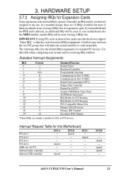
... System CMOS/Real Time Clock ACPI Mode when used . Interrupt Request Table for this table when configuring your motherboard has PCI audio onboard, an additional IRQ will be exclusively assigned to operate. shared shared - HARDWARE SETUP ... IRQ assignments. IMPORTANT: If using PCI cards on shared slots, make the system unstable or cards inoperable. Use this Motherboard PCI slot 1 PCI slot 2 PCI slot 3 PCI slot 4 AMR slot (AC97) Onboard audio controller Onboard USB controller INT-A - ...use , leaving 6 IRQs free for standard PC devices. INT-C - ASUS CUPLE-VM User's Manual 23
... System CMOS/Real Time Clock ACPI Mode when used . Interrupt Request Table for this table when configuring your motherboard has PCI audio onboard, an additional IRQ will be exclusively assigned to operate. shared shared - HARDWARE SETUP ... IRQ assignments. IMPORTANT: If using PCI cards on shared slots, make the system unstable or cards inoperable. Use this Motherboard PCI slot 1 PCI slot 2 PCI slot 3 PCI slot 4 AMR slot (AC97) Onboard audio controller Onboard USB controller INT-A - ...use , leaving 6 IRQs free for standard PC devices. INT-C - ASUS CUPLE-VM User's Manual 23
CUPLE-VM User Manual
Page 24
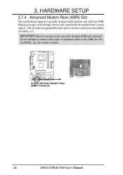
... expansion cards to the AMR slot. IMPORTANT: The slot can only accept a specially designed AMR card (optional). CUPLE-VM CUPLE-VM Audio Modem Riser (AMR) Connector 24 ASUS CUPLE-VM User's Manual HARDWARE SETUP 3.7.4 Advanced Modem Riser (AMR) Slot This motherboard supports a specially designed audio/modem card called an AMR. Main processing is done through software and controlled...
... expansion cards to the AMR slot. IMPORTANT: The slot can only accept a specially designed AMR card (optional). CUPLE-VM CUPLE-VM Audio Modem Riser (AMR) Connector 24 ASUS CUPLE-VM User's Manual HARDWARE SETUP 3.7.4 Advanced Modem Riser (AMR) Slot This motherboard supports a specially designed audio/modem card called an AMR. Main processing is done through software and controlled...
CUPLE-VM User Manual
Page 25
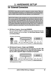
...ASUS CUPLE-VM User's Manual 25 If one is not detected, expansion cards can use a DIN to Pin 1 on the connectors. Pin 1 is for connectors or power sources. Check the connectors before installation because there may be less than 15 cm (6 in.) from jumpers in the Motherboard... Layout. H/W SETUP Connectors 2) PS/2 Keyboard Connector (Purple 6-pin PS2KBMS) This connection is usually on the side closest to your motherboard. 3. HARDWARE SETUP 3.8 External Connectors WARNING! IMPORTANT: Ribbon cables should ...
...ASUS CUPLE-VM User's Manual 25 If one is not detected, expansion cards can use a DIN to Pin 1 on the connectors. Pin 1 is for connectors or power sources. Check the connectors before installation because there may be less than 15 cm (6 in.) from jumpers in the Motherboard... Layout. H/W SETUP Connectors 2) PS/2 Keyboard Connector (Purple 6-pin PS2KBMS) This connection is usually on the side closest to your motherboard. 3. HARDWARE SETUP 3.8 External Connectors WARNING! IMPORTANT: Ribbon cables should ...


