C8HM70-I User's Manual
Page 1
Motherboard C8HM70-I SERIES • C8HM70-I • C8HM70-I/HDMI
Motherboard C8HM70-I SERIES • C8HM70-I • C8HM70-I/HDMI
C8HM70-I User's Manual
Page 3
Contents Safety information...v About this guide...vi C8HM70-I SERIES specifications summary viii Package contents...x Product introduction 1.1 Before you proceed 1-1 1.2 Motherboard overview 1-2 1.2.1 Placement direction 1-2 1.2.2 Screw holes 1-2 1.2.3 Motherboard layout 1-3 1.2.4 Layout contents 1-3 1.3 Central Processing ... DVD information 1-15 BIOS information 2.1 Managing and updating your BIOS 2-1 2.1.1 ASUS Update utility 2-1 2.1.2 ASUS EZ Flash 2 2-2 2.1.3 ASUS CrashFree BIOS 3 utility 2-3 2.1.4 ASUS BIOS Updater 2-4 2.2 BIOS setup program 2-6 2.3 Main menu 2-10 2.3.1 ...
Contents Safety information...v About this guide...vi C8HM70-I SERIES specifications summary viii Package contents...x Product introduction 1.1 Before you proceed 1-1 1.2 Motherboard overview 1-2 1.2.1 Placement direction 1-2 1.2.2 Screw holes 1-2 1.2.3 Motherboard layout 1-3 1.2.4 Layout contents 1-3 1.3 Central Processing ... DVD information 1-15 BIOS information 2.1 Managing and updating your BIOS 2-1 2.1.1 ASUS Update utility 2-1 2.1.2 ASUS EZ Flash 2 2-2 2.1.3 ASUS CrashFree BIOS 3 utility 2-3 2.1.4 ASUS BIOS Updater 2-4 2.2 BIOS setup program 2-6 2.3 Main menu 2-10 2.3.1 ...
C8HM70-I User's Manual
Page 5
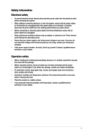
...If possible, disconnect all power cables from the existing system before you add a device. • Before connecting or removing signal cables from the motherboard, ensure that your power supply is broken, do not try to the correct voltage in any damage, contact your retailer. Operation safety •...; Before installing the motherboard and adding devices on a stable surface. • If you are using the product, ensure all cables are correctly connected and the power...
...If possible, disconnect all power cables from the existing system before you add a device. • Before connecting or removing signal cables from the motherboard, ensure that your power supply is broken, do not try to the correct voltage in any damage, contact your retailer. Operation safety •...; Before installing the motherboard and adding devices on a stable surface. • If you are using the product, ensure all cables are correctly connected and the power...
C8HM70-I User's Manual
Page 6
...you need when installing and configuring the motherboard. Detailed descriptions of the BIOS parameters are not part of the motherboard and the new technology it supports. • Chapter 2: BIOS information This chapter tells how to the ASUS contact information. 2. Refer to change system...parts: • Chapter 1: Product introduction This chapter describes the features of the standard package. vi ASUS websites The ASUS website provides updated information on ASUS hardware and software products. About this guide is organized This guide contains the following sources for additional ...
...you need when installing and configuring the motherboard. Detailed descriptions of the BIOS parameters are not part of the motherboard and the new technology it supports. • Chapter 2: BIOS information This chapter tells how to the ASUS contact information. 2. Refer to change system...parts: • Chapter 1: Product introduction This chapter describes the features of the standard package. vi ASUS websites The ASUS website provides updated information on ASUS hardware and software products. About this guide is organized This guide contains the following sources for additional ...
C8HM70-I User's Manual
Page 10
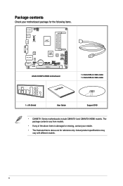
... module) VGA Super I/O LAN_USB34 RTL 8111F AUDIO AAFP ALC 887 Intel® HM70 64Mb BIOS SATA6G_1 SATA3G_1 EATXPWR Lithium Cell CMOS Power USB1112 CLRTC F_PANEL C8HM70-I/HDMI SPEAKER CHASSIS PCIEX16_1 SB_PWR ASUS C8HM70-I/HDMI motherboard User Manual 1 x Serial ATA 3.0 Gb/s cable 1 x Serial ATA 6.0 Gb/s cable 1 x I/O-Shield User Guide Support DVD •...
... module) VGA Super I/O LAN_USB34 RTL 8111F AUDIO AAFP ALC 887 Intel® HM70 64Mb BIOS SATA6G_1 SATA3G_1 EATXPWR Lithium Cell CMOS Power USB1112 CLRTC F_PANEL C8HM70-I/HDMI SPEAKER CHASSIS PCIEX16_1 SB_PWR ASUS C8HM70-I/HDMI motherboard User Manual 1 x Serial ATA 3.0 Gb/s cable 1 x Serial ATA 6.0 Gb/s cable 1 x I/O-Shield User Guide Support DVD •...
C8HM70-I User's Manual
Page 11
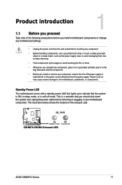
... on a grounded antistatic pad or in the bag that came with a standby power LED that lights up to the motherboard, peripherals, or components. SB_PWR C8HM70-I/HDMI ON OFF Standby Power Powered Off C8HM70-I/HDMI Onboard LED ASUS C8HM70-I Series 1-1 This is a reminder that you should shut down the system and unplug the power cable before removing or...
... on a grounded antistatic pad or in the bag that came with a standby power LED that lights up to the motherboard, peripherals, or components. SB_PWR C8HM70-I/HDMI ON OFF Standby Power Powered Off C8HM70-I/HDMI Onboard LED ASUS C8HM70-I Series 1-1 This is a reminder that you should shut down the system and unplug the power cable before removing or...
C8HM70-I User's Manual
Page 12
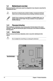
... user guide are for C8HM70-I/HDMI only. 1.2.1 Placement direction When installing the motherboard, ensure that you place it . 1.2 Motherboard overview Before you install the motherboard, study the configuration of your chassis to ensure that the motherboard fits into the holes indicated by circles to secure the motherboard to the chassis. C8HM70-I Series motherboards include C8HM70-I and C8HM70-I /HDMI Chapter 1: Product introduction The...
... user guide are for C8HM70-I/HDMI only. 1.2.1 Placement direction When installing the motherboard, ensure that you place it . 1.2 Motherboard overview Before you install the motherboard, study the configuration of your chassis to ensure that the motherboard fits into the holes indicated by circles to secure the motherboard to the chassis. C8HM70-I Series motherboards include C8HM70-I and C8HM70-I /HDMI Chapter 1: Product introduction The...
C8HM70-I User's Manual
Page 13
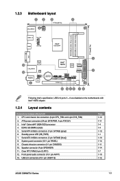
... 8. DDR3 SO-DIMM sockets 5. Serial ATA 6.0Gb/s connectors (7-pin SATA6G [gray]) 6. 1.2.3 Motherboard layout 1 2 3 4 17.0cm(6.7in) KB_USB910 ATX12V USB3_12 CHA_FAN HDMI CPU_FAN Intel® Celeron847 DDR3 DIMM_B1 (64bit, 204-pin module) DDR3 DIMM_A1 (64bit, 204-pin ...11 1-4 1-4 1-13 1-1 1-13 1-14 1-11 1-14 1-7 1-10 1-12 ASUS C8HM70-I /HDMI PCIEX16_1 F_PANEL SPEAKER CHASSIS SB_PWR 11 10 9 8 7 6 Following Intel's specification, USB 2.0 ports 5 ~ 8 are disabled on the motherboards with Intel® HM70 chipset. 1.2.4 Layout contents Connectors/Jumpers/Slots/LED 1. System...
... 8. DDR3 SO-DIMM sockets 5. Serial ATA 6.0Gb/s connectors (7-pin SATA6G [gray]) 6. 1.2.3 Motherboard layout 1 2 3 4 17.0cm(6.7in) KB_USB910 ATX12V USB3_12 CHA_FAN HDMI CPU_FAN Intel® Celeron847 DDR3 DIMM_B1 (64bit, 204-pin module) DDR3 DIMM_A1 (64bit, 204-pin ...11 1-4 1-4 1-13 1-1 1-13 1-14 1-11 1-14 1-7 1-10 1-12 ASUS C8HM70-I /HDMI PCIEX16_1 F_PANEL SPEAKER CHASSIS SB_PWR 11 10 9 8 7 6 Following Intel's specification, USB 2.0 ports 5 ~ 8 are disabled on the motherboards with Intel® HM70 chipset. 1.2.4 Layout contents Connectors/Jumpers/Slots/LED 1. System...
C8HM70-I User's Manual
Page 14
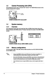
1.3 Central Processing Unit (CPU) The motherboard comes with two Double Data Rate 3 (DDR3) Small Outline Dual Inline Memory Modules (SO-DIMM) sockets. Intel® Celeron847 C8HM70-I/HDMI C8HM70-I /HDMI 204-pin DDR3 DIMM sockets 1.4.2 Memory configurations You may install 512MB... of 3GB system memory. • This motherboard does not support DIMMs made up of the DDR3 DIMM sockets: DIMM_B1 DIMM_A1 Channel Channel A Channel B Sockets DIMM_A1 DIMM_B1 C8HM70-I/HDMI C8HM70-I /HDMI CPU Celeron847 1.4 System memory 1.4.1 Overview This motherboard comes with an onboard Intel® Celeron™...
1.3 Central Processing Unit (CPU) The motherboard comes with two Double Data Rate 3 (DDR3) Small Outline Dual Inline Memory Modules (SO-DIMM) sockets. Intel® Celeron847 C8HM70-I/HDMI C8HM70-I /HDMI 204-pin DDR3 DIMM sockets 1.4.2 Memory configurations You may install 512MB... of 3GB system memory. • This motherboard does not support DIMMs made up of the DDR3 DIMM sockets: DIMM_B1 DIMM_A1 Channel Channel A Channel B Sockets DIMM_A1 DIMM_B1 C8HM70-I/HDMI C8HM70-I /HDMI CPU Celeron847 1.4 System memory 1.4.1 Overview This motherboard comes with an onboard Intel® Celeron™...

C8HM70-I User's Manual
Page 15
...-C8KM9-NBE FSFF65F-C8KM9-NAE KVR1333D3S9/1G KVR1333D3S9/2G KVR16S11/8 AS8F8G73F-DJ2 M471B5773CHS-CH9 Size SS/ DS Chip Brand Chip No. Visit the ASUS website at www.asus.com for the latest QVL. Size SS/ DS A-Data Apacer Apacer CORSAIR CORSAIR G.SKILL G.SKILL GEIL GEIL GEIL Hynix Kingmax Kingmax Kingmax...-GN-F - 1.5V · · 2GB DS PSC A3P1GF3FGF - - · · 2GB DS SAMSUNG K4B2G0846C - - · · DDR3-1067 MHz capability Vendors Part No. ASUS C8HM70-I Series Motherboard Qualified Vendors Lists (QVL) DDR3-1333 MHz capability Vendors Part No.
...-C8KM9-NBE FSFF65F-C8KM9-NAE KVR1333D3S9/1G KVR1333D3S9/2G KVR16S11/8 AS8F8G73F-DJ2 M471B5773CHS-CH9 Size SS/ DS Chip Brand Chip No. Visit the ASUS website at www.asus.com for the latest QVL. Size SS/ DS A-Data Apacer Apacer CORSAIR CORSAIR G.SKILL G.SKILL GEIL GEIL GEIL Hynix Kingmax Kingmax Kingmax...-GN-F - 1.5V · · 2GB DS PSC A3P1GF3FGF - - · · 2GB DS SAMSUNG K4B2G0846C - - · · DDR3-1067 MHz capability Vendors Part No. ASUS C8HM70-I Series Motherboard Qualified Vendors Lists (QVL) DDR3-1333 MHz capability Vendors Part No.
C8HM70-I User's Manual
Page 16
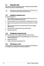
Remove the system unit cover (if your motherboard is completely seated on the slot. 5. Align the card connector with the PCI Express specifications. 1-6 Chapter 1: Product introduction The following sub‑sections describe the ... the documentation that you may cause you removed earlier. 6. Remove the bracket opposite the slot that came with the screw you physical injury and damage motherboard components. 1.5.1 Installing an expansion card To install an expansion card: 1. Keep the screw for the expansion card. 1.5.3 PCI Express x16 slot This...
Remove the system unit cover (if your motherboard is completely seated on the slot. 5. Align the card connector with the PCI Express specifications. 1-6 Chapter 1: Product introduction The following sub‑sections describe the ... the documentation that you may cause you removed earlier. 6. Remove the bracket opposite the slot that came with the screw you physical injury and damage motherboard components. 1.5.1 Installing an expansion card To install an expansion card: 1. Keep the screw for the expansion card. 1.5.3 PCI Express x16 slot This...

C8HM70-I User's Manual
Page 20
...`97 audio standard. Front panel audio connector (10-1 pin AAFP) This connector is set to this connector. Connect one end of the motherboard's high-definition audio capability. • If you want to connect a high-definition front panel audio module to this connector, set the...AAFP PIN 1 PIN 1 MIC2 MICPWR Line out_R NC Line out_L PORT1 L PORT1 R PORT2 R SENSE_SEND PORT2 L C8HM70-I/HDMI HD-audio-compliant Legacy AC'97 pin definition compliant definition C8HM70-I /O module that you connect a high-definition front panel audio module to this connector to avail of the front panel...
...`97 audio standard. Front panel audio connector (10-1 pin AAFP) This connector is set to this connector. Connect one end of the motherboard's high-definition audio capability. • If you want to connect a high-definition front panel audio module to this connector, set the...AAFP PIN 1 PIN 1 MIC2 MICPWR Line out_R NC Line out_L PORT1 L PORT1 R PORT2 R SENSE_SEND PORT2 L C8HM70-I/HDMI HD-audio-compliant Legacy AC'97 pin definition compliant definition C8HM70-I /O module that you connect a high-definition front panel audio module to this connector to avail of the front panel...
C8HM70-I User's Manual
Page 22
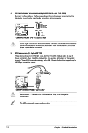
USB+5V USB_P11USB_P11+ GND NC PIN 1 USB+5V USB_P12USB_P12+ GND USB1112 C8HM70-I/HDMI C8HM70-I /HDMI CPU fan connector Do not forget to connect the fan cables to the fan connectors. Insufficient air flow inside the system may damage the motherboard components. These are for USB 2.0 ports. The USB module cable is purchased separately. 1-12 Chapter 1: Product...
USB+5V USB_P11USB_P11+ GND NC PIN 1 USB+5V USB_P12USB_P12+ GND USB1112 C8HM70-I/HDMI C8HM70-I /HDMI CPU fan connector Do not forget to connect the fan cables to the fan connectors. Insufficient air flow inside the system may damage the motherboard components. These are for USB 2.0 ports. The USB module cable is purchased separately. 1-12 Chapter 1: Product...
C8HM70-I User's Manual
Page 25
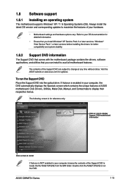
... Click an item to install If Autorun is NOT enabled in your computer, browse the contents of ASUS motherboard. ASUS C8HM70-I Series 1-15 Visit the ASUS website at any time without notice. The following screen is enabled in your computer, the DVD automatically displays the ...Specials screen which contains the unique features of the Support DVD to avail all motherboard features. Double-click the ASSETUP.EXE to display their respective ...
... Click an item to install If Autorun is NOT enabled in your computer, browse the contents of ASUS motherboard. ASUS C8HM70-I Series 1-15 Visit the ASUS website at any time without notice. The following screen is enabled in your computer, the DVD automatically displays the ...Specials screen which contains the unique features of the Support DVD to avail all motherboard features. Double-click the ASSETUP.EXE to display their respective ...
C8HM70-I User's Manual
Page 27
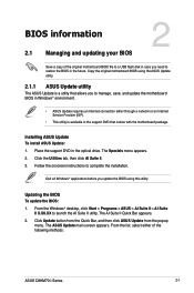
... either through a network or an Internet Service Provider (ISP). • This utility is a utility that comes with the motherboard package. BIOS information 2.1 Managing and updating your BIOS 2 Save a copy of the following methods: ASUS C8HM70-I Series 2-1 Click the Utilities tab, then click AI Suite II. 3. Updating the BIOS To update the BIOS: 1. The...
... either through a network or an Internet Service Provider (ISP). • This utility is a utility that comes with the motherboard package. BIOS information 2.1 Managing and updating your BIOS 2 Save a copy of the following methods: ASUS C8HM70-I Series 2-1 Click the Utilities tab, then click AI Suite II. 3. Updating the BIOS To update the BIOS: 1. The...
C8HM70-I User's Manual
Page 29
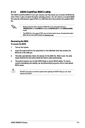
... shut down or reset the system while updating the BIOS! Doing so can restore a corrupted BIOS file using the motherboard support DVD or a USB flash drive that contains the BIOS file to the USB port. 3. ASUS C8HM70-I /HDMI model. • The BIOS file in the removable device to C8HM70I.CAP for the... C8HM70-I model and HM70IH.CAP for the BIOS file. You can cause system boot failure! When found, the utility ...
... shut down or reset the system while updating the BIOS! Doing so can restore a corrupted BIOS file using the motherboard support DVD or a USB flash drive that contains the BIOS file to the USB port. 3. ASUS C8HM70-I /HDMI model. • The BIOS file in the removable device to C8HM70I.CAP for the... C8HM70-I model and HM70IH.CAP for the BIOS file. You can cause system boot failure! When found, the utility ...
C8HM70-I User's Manual
Page 30
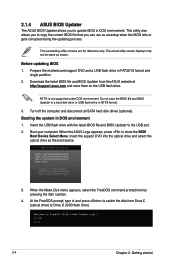
... motherboard support DVD and a USB flash drive in NTFS format. 3. NTFS is not supported under DOS environment. Insert the USB flash drive with the latest BIOS file and BIOS Updater to show the BIOS Boot Device Select Menu. At the FreeDOS prompt, type d: and press to switch the disk from the ASUS... may not be same as the boot device. 3. Insert the support DVD into the optical drive and select the optical drive as shown. When the ASUS Logo appears, press to the USB port. 2. Download the latest BIOS file and BIOS Updater from Drive C (optical drive) to update BIOS in DOS ...
... motherboard support DVD and a USB flash drive in NTFS format. 3. NTFS is not supported under DOS environment. Insert the USB flash drive with the latest BIOS file and BIOS Updater to show the BIOS Boot Device Select Menu. At the FreeDOS prompt, type d: and press to switch the disk from the ASUS... may not be same as the boot device. 3. Insert the support DVD into the optical drive and select the optical drive as shown. When the ASUS Logo appears, press to the USB port. 2. Download the latest BIOS file and BIOS Updater from Drive C (optical drive) to update BIOS in DOS ...

C8HM70-I User's Manual
Page 32
...on . We recommend to always shut down the system properly from a running operating system can cause damage to your screen. • Visit the ASUS website at startup: • Press during the Power-On Self Test (POST). Select the Load Optimized Defaults item under the Exit menu. Do... the BIOS setup program. • If the system becomes unstable after changing any BIOS setting, try to clear the CMOS and reset the motherboard to ensure system compatibility and stability. See section 2.9 Exit Menu for information on how to force reset from the operating system. • ...
...on . We recommend to always shut down the system properly from a running operating system can cause damage to your screen. • Visit the ASUS website at startup: • Press during the Power-On Self Test (POST). Select the Load Optimized Defaults item under the Exit menu. Do... the BIOS setup program. • If the system becomes unstable after changing any BIOS setting, try to clear the CMOS and reset the motherboard to ensure system compatibility and stability. See section 2.9 Exit Menu for information on how to force reset from the operating system. • ...
C8HM70-I User's Manual
Page 33
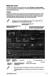
... options vary depending on the devices you enter the BIOS setup program. Refer to the Setup Mode item in the EZ Mode/Advanced Mode screen. ASUS C8HM70-I Series 2-7 To access the Advanced Mode, click Exit/Advanced Mode, then select Advanced Mode. BIOS menu screen The BIOS setup program can be ...menu or from the Exit/Advanced Mode button in section 2.7 Boot menu for entering the BIOS setup program can be changed. Displays the CPU/motherboard temperature, CPU/5V/3.3V/12V voltage output, CPU/chassis fan speed Selects the display language of the BIOS setup program Exits the BIOS setup ...
... options vary depending on the devices you enter the BIOS setup program. Refer to the Setup Mode item in the EZ Mode/Advanced Mode screen. ASUS C8HM70-I Series 2-7 To access the Advanced Mode, click Exit/Advanced Mode, then select Advanced Mode. BIOS menu screen The BIOS setup program can be ...menu or from the Exit/Advanced Mode button in section 2.7 Boot menu for entering the BIOS setup program can be changed. Displays the CPU/motherboard temperature, CPU/5V/3.3V/12V voltage output, CPU/chassis fan speed Selects the display language of the BIOS setup program Exits the BIOS setup ...
C8HM70-I User's Manual
Page 44
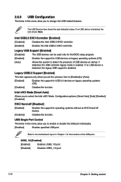
... operating systems (OS). [Disabled] Disables the function. The USB Devices item shows the auto-detected values. Intel xHCI Mode [Smart Auto] Allows you to the motherboard layout in Chapter 1 for operating systems without an EHCI hand‑off feature. [Disabled] Disables the function. Configuration options: [Smart Auto] [Auto] [Enabled] [Disabled] EHCI...
... operating systems (OS). [Disabled] Disables the function. The USB Devices item shows the auto-detected values. Intel xHCI Mode [Smart Auto] Allows you to the motherboard layout in Chapter 1 for operating systems without an EHCI hand‑off feature. [Disabled] Disables the function. Configuration options: [Smart Auto] [Auto] [Enabled] [Disabled] EHCI...


