
B75M-PLUS User's Manual
Page 2
... without intent to this information. This offer is dependent on the preferred carrier and the location where you want to have it from http://support.asus.com/download or (2) for the cost of reproduction and shipment, which you to the source code of the product is authorized in this ...licenses are used only for identification or explanation and to the owners' benefit, without the express written permission of the product for free by ASUS; ASUS PROVIDES THIS MANUAL "AS IS" WITHOUT WARRANTY OF ANY KIND, EITHER EXPRESS OR IMPLIED, INCLUDING BUT NOT LIMITED TO THE IMPLIED WARRANTIES OR...
... without intent to this information. This offer is dependent on the preferred carrier and the location where you want to have it from http://support.asus.com/download or (2) for the cost of reproduction and shipment, which you to the source code of the product is authorized in this ...licenses are used only for identification or explanation and to the owners' benefit, without the express written permission of the product for free by ASUS; ASUS PROVIDES THIS MANUAL "AS IS" WITHOUT WARRANTY OF ANY KIND, EITHER EXPRESS OR IMPLIED, INCLUDING BUT NOT LIMITED TO THE IMPLIED WARRANTIES OR...
B75M-PLUS User's Manual
Page 3
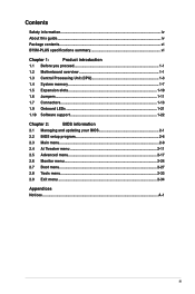
Contents Safety information...iv About this guide...iv Package contents...vi B75M-PLUS specifications summary vi Chapter 1: Product introduction 1.1 Before you proceed 1-1 1.2 Motherboard overview 1-1 1.3 Central Processing Unit (CPU 1-3 1.4 System memory 1-7 1.5 Expansion slots 1-10 1.6 Jumpers...1-11 1.7 Connectors 1-13 1.9 Onboard LEDs 1-21 1.10 Software support 1-22 Chapter 2: BIOS information 2.1 Managing and updating your BIOS 2-1 2.2 BIOS setup...
Contents Safety information...iv About this guide...iv Package contents...vi B75M-PLUS specifications summary vi Chapter 1: Product introduction 1.1 Before you proceed 1-1 1.2 Motherboard overview 1-1 1.3 Central Processing Unit (CPU 1-3 1.4 System memory 1-7 1.5 Expansion slots 1-10 1.6 Jumpers...1-11 1.7 Connectors 1-13 1.9 Onboard LEDs 1-21 1.10 Software support 1-22 Chapter 2: BIOS information 2.1 Managing and updating your BIOS 2-1 2.2 BIOS setup...

B75M-PLUS User's Manual
Page 4
... that the power cables for the devices are unplugged before you detect any area where it may become wet. • Place the product on it supports. • Chapter 2: BIOS information This chapter tells how to the correct voltage in your area. These devices could interrupt the grounding circuit. • Ensure that...
... that the power cables for the devices are unplugged before you detect any area where it may become wet. • Place the product on it supports. • Chapter 2: BIOS information This chapter tells how to the correct voltage in your area. These devices could interrupt the grounding circuit. • Ensure that...
B75M-PLUS User's Manual
Page 6
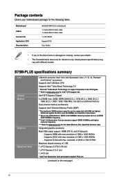
... may vary with max. Package contents Check your motherboard package for the following items. Motherboard Cables Accessories Application DVD Documentation ASUS B75M-PLUS motherboard 1 x Serial ATA 6.0 Gb/s cable 1 x Serial ATA 3.0 Gb/s cable 1 x I/O Shield Support DVD User Guide • If any of the above items is damaged or missing, contact your retailer. • The illustrated...
... may vary with max. Package contents Check your motherboard package for the following items. Motherboard Cables Accessories Application DVD Documentation ASUS B75M-PLUS motherboard 1 x Serial ATA 6.0 Gb/s cable 1 x Serial ATA 3.0 Gb/s cable 1 x I/O Shield Support DVD User Guide • If any of the above items is damaged or missing, contact your retailer. • The illustrated...
B75M-PLUS User's Manual
Page 7
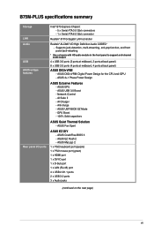
...GPU Boost - 100% Solid capacitors ASUS Quiet Thermal Solution - ASUS 3+1 Phase Power Design ASUS Eclusive Features - AI Suite II - ASUS UEFI BIOS EZ Mode - ASUS CrashFree BIOS 3 - Network iControl - ASUS EZ Flash 2 - B75M-PLUS specifications summary Storage LAN Audio USB ASUS unique features Rear panel I/O ports...3.0 ports 3 x Audio jacks (continued on the next page) vii Supports jack-detection, multi-streaming, anti-pop function, and front panel jack-retasking * Use a chassis with HD audio module in the front panel to support an 8-channel audio output. 4 x USB 3.0 ports (2 ports at ...
...GPU Boost - 100% Solid capacitors ASUS Quiet Thermal Solution - ASUS 3+1 Phase Power Design ASUS Eclusive Features - AI Suite II - ASUS UEFI BIOS EZ Mode - ASUS CrashFree BIOS 3 - Network iControl - ASUS EZ Flash 2 - B75M-PLUS specifications summary Storage LAN Audio USB ASUS unique features Rear panel I/O ports...3.0 ports 3 x Audio jacks (continued on the next page) vii Supports jack-detection, multi-streaming, anti-pop function, and front panel jack-retasking * Use a chassis with HD audio module in the front panel to support an 8-channel audio output. 4 x USB 3.0 ports (2 ports at ...
B75M-PLUS User's Manual
Page 8
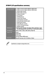
viii B75M-PLUS specifications summary Internal connectors/ switches/ buttons BIOS features Manageability Support DVD Form factor 1 x USB 3.0 connector supports additional 2 USB 3.0 ports 2 x USB 2.0 connectors support additional 4 USB 2.0 ports 1 x SATA 6.0 Gb/s connector 5 x SATA 3.0 Gb/s connectors 1 x COM port connector 1 x LPT connector 1 ... DMI2.0, WfM2.0, SM BIOS 2.7, ACPI 2.0a, Multi-language BIOS, ASUS EZ Flash 2, ASUS CrashFree BIOS 3 WfM 2.0, DMI 2.0, WOL by PME, WOR by PME, PXE Drivers ASUS utilities ASUS Update Anti-virus software (OEM version) MicroATX form factor: 8.9"x 7.8" (...
viii B75M-PLUS specifications summary Internal connectors/ switches/ buttons BIOS features Manageability Support DVD Form factor 1 x USB 3.0 connector supports additional 2 USB 3.0 ports 2 x USB 2.0 connectors support additional 4 USB 2.0 ports 1 x SATA 6.0 Gb/s connector 5 x SATA 3.0 Gb/s connectors 1 x COM port connector 1 x LPT connector 1 ... DMI2.0, WfM2.0, SM BIOS 2.7, ACPI 2.0a, Multi-language BIOS, ASUS EZ Flash 2, ASUS CrashFree BIOS 3 WfM 2.0, DMI 2.0, WOL by PME, WOR by PME, PXE Drivers ASUS utilities ASUS Update Anti-virus software (OEM version) MicroATX form factor: 8.9"x 7.8" (...

B75M-PLUS User's Manual
Page 16
....com/ kb/929605/en-us • This motherboard does not support DIMMs made up of 512 megabits (Mb) chips or less. • Memory modules with 8GB or above DIMMs. ASUS will update the memory QVL once the DIMMs are available in the market. • The default memory operation frequency is dependent on...
....com/ kb/929605/en-us • This motherboard does not support DIMMs made up of 512 megabits (Mb) chips or less. • Memory modules with 8GB or above DIMMs. ASUS will update the memory QVL once the DIMMs are available in the market. • The default memory operation frequency is dependent on...

B75M-PLUS User's Manual
Page 18
... card After installing the expansion card, configure it and make the necessary hardware settings for information on shared slots, ensure that the drivers support "Share IRQ" or that came with the screw you physical injury and damage motherboard components. 1.5.1 Installing an expansion card To install an...Otherwise, conflicts will arise between the two PCI groups, making the system unstable and the card inoperable. 1.5.3 PCI slot The PCI slot supports cards such as a LAN card, SCSI card, USB card, and other cards that comply with PCI specifications. 1.5.4 PCI Express 2.0 x1 slot ...
... card After installing the expansion card, configure it and make the necessary hardware settings for information on shared slots, ensure that the drivers support "Share IRQ" or that came with the screw you physical injury and damage motherboard components. 1.5.1 Installing an expansion card To install an...Otherwise, conflicts will arise between the two PCI groups, making the system unstable and the card inoperable. 1.5.3 PCI slot The PCI slot supports cards such as a LAN card, SCSI card, USB card, and other cards that comply with PCI specifications. 1.5.4 PCI Express 2.0 x1 slot ...
B75M-PLUS User's Manual
Page 19
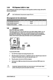
... RTC RAM To erase the RTC RAM: 1. Turn OFF the computer and unplug the power cord. 2. Plug the power cord and turn ON the computer. 4. ASUS B75M-PLUS 1-11 Removing the cap will cause system boot failure! Realtek 8111G controller shared - - - - - - - 1.6 Jumpers Clear RTC RAM (3-pin CLRTC) This .... Hold down the key during the boot process and enter BIOS setup to pins 2-3. Intel® 3rd Generation Core processors support PCIe 3.0. 1.5.5 PCI Express 3.0/2.0 x1 slot This motherboard supports one PCI Express 3.0/2.0 graphics card that comply with the PCI Express specifications.
... RTC RAM To erase the RTC RAM: 1. Turn OFF the computer and unplug the power cord. 2. Plug the power cord and turn ON the computer. 4. ASUS B75M-PLUS 1-11 Removing the cap will cause system boot failure! Realtek 8111G controller shared - - - - - - - 1.6 Jumpers Clear RTC RAM (3-pin CLRTC) This .... Hold down the key during the boot process and enter BIOS setup to pins 2-3. Intel® 3rd Generation Core processors support PCIe 3.0. 1.5.5 PCI Express 3.0/2.0 x1 slot This motherboard supports one PCI Express 3.0/2.0 graphics card that comply with the PCI Express specifications.
B75M-PLUS User's Manual
Page 22
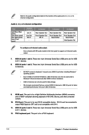
... in 2, 4, 6, or 8channel configuration. HDMI port. These two 4-pin Universal Serial Bus (USB) ports are for USB 3.0 devices. • DO NOT connect a keyboard / mouse to support an 8-channel audio output. 7.
... in 2, 4, 6, or 8channel configuration. HDMI port. These two 4-pin Universal Serial Bus (USB) ports are for USB 3.0 devices. • DO NOT connect a keyboard / mouse to support an 8-channel audio output. 7.
B75M-PLUS User's Manual
Page 23
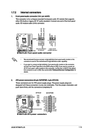
...Line out_R NC Line out_L PORT1 L PORT1 R PORT2 R SENSE_SEND PORT2 L B75M-PLUS HD-audio-compliant Legacy AC'97 pin definition compliant definition B75M-PLUS Front panel audio connector • We recommend that supports either HD Audio or legacy AC`97 audio standard. Connect one end of ... +12V DC +12V DC B75M-PLUS GND GND +3 Volts +12 Volts +12 Volts +5V Standby Power OK PIN 1 GND +5 Volts GND +5 Volts GND +3 Volts +3 Volts PIN 1 B75M-PLUS ATX power connectors GND +5 Volts +5 Volts +5 Volts -5 Volts GND GND GND PSON# GND -12 Volts +3 Volts ASUS B75M-PLUS 1-15
...Line out_R NC Line out_L PORT1 L PORT1 R PORT2 R SENSE_SEND PORT2 L B75M-PLUS HD-audio-compliant Legacy AC'97 pin definition compliant definition B75M-PLUS Front panel audio connector • We recommend that supports either HD Audio or legacy AC`97 audio standard. Connect one end of ... +12V DC +12V DC B75M-PLUS GND GND +3 Volts +12 Volts +12 Volts +5V Standby Power OK PIN 1 GND +5 Volts GND +5 Volts GND +3 Volts +3 Volts PIN 1 B75M-PLUS ATX power connectors GND +5 Volts +5 Volts +5 Volts -5 Volts GND GND GND PSON# GND -12 Volts +3 Volts ASUS B75M-PLUS 1-15
B75M-PLUS User's Manual
Page 24
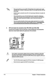
.../PowerSupplyCalculator/PSCalculator.aspx?SLanguage=en-us for your system, refer to the Recommended Power Supply Wattage Calculator at http://support.asus. CPU_FAN CHA_FAN B75M-PLUS B75M-PLUS Fan connectors Do not forget to connect the fan cables to install additional devices. Insufficient air flow inside the ...with higher power output when configuring a system with a minimum of maximum 1A (12W) fan power. • Only the 4-pin fan supports the ASUS Fan Xpert feature. CPU and chassis fan connectors (4-pin CPU_FAN, 4-pin CHA_FAN) Connect the fan cables to connect the 4-pin ATX ...
.../PowerSupplyCalculator/PSCalculator.aspx?SLanguage=en-us for your system, refer to the Recommended Power Supply Wattage Calculator at http://support.asus. CPU_FAN CHA_FAN B75M-PLUS B75M-PLUS Fan connectors Do not forget to connect the fan cables to install additional devices. Insufficient air flow inside the ...with higher power output when configuring a system with a minimum of maximum 1A (12W) fan power. • Only the 4-pin fan supports the ASUS Fan Xpert feature. CPU and chassis fan connectors (4-pin CPU_FAN, 4-pin CHA_FAN) Connect the fan cables to connect the 4-pin ATX ...
B75M-PLUS User's Manual
Page 25
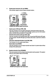
The IDE LED lights up when you hear system beeps and warnings. SPEAKER B75M-PLUS PIN 1 B75M-PLUS Speaker Out Connector +5V GND GND Speaker Out ASUS B75M-PLUS 1-17 Connect the chassis power LED cable to the HDD. • ATX power button/soft-off button (2-pin PWR_BTN) This connector is... HDD_LED) This 2-pin connector is for system reboot without turning off the system power. 5. System panel connector (10-1 pin PANEL) This connector supports several chassis-mounted functions. The system power LED lights up or flashes when data is for the chassis-mounted system warning speaker.
The IDE LED lights up when you hear system beeps and warnings. SPEAKER B75M-PLUS PIN 1 B75M-PLUS Speaker Out Connector +5V GND GND Speaker Out ASUS B75M-PLUS 1-17 Connect the chassis power LED cable to the HDD. • ATX power button/soft-off button (2-pin PWR_BTN) This connector is... HDD_LED) This 2-pin connector is for system reboot without turning off the system power. 5. System panel connector (10-1 pin PANEL) This connector supports several chassis-mounted functions. The system power LED lights up or flashes when data is for the chassis-mounted system warning speaker.
B75M-PLUS User's Manual
Page 27
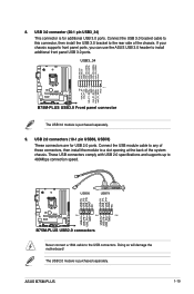
... a slot opening at the back of the chassis. USB3_34 IntA_P2_D+ IntA_P2_DGND IntA_P2_SSTX+ IntA_P2_SSTXGND IntA_P2_SSRX+ IntA_P2_SSRXVbus ID IntA_P1_D+ IntA_P1_D- ASUS B75M-PLUS 1-19 8. USB 2.0 connectors (10-1 pin USB56, USB78) These connectors are for additional USB 3.0 ports. USB56 USB78 ... to 480Mbps connection speed. Vbus B75M-PLUS PIN 1 B75M-PLUS USB3.0 Front panel connector The USB 3.0 module is purchased separately. The USB 2.0 module is purchased separately. 9. These USB connectors comply with USB 2.0 specifications and supports up to the rear side of...
... a slot opening at the back of the chassis. USB3_34 IntA_P2_D+ IntA_P2_DGND IntA_P2_SSTX+ IntA_P2_SSTXGND IntA_P2_SSRX+ IntA_P2_SSRXVbus ID IntA_P1_D+ IntA_P1_D- ASUS B75M-PLUS 1-19 8. USB 2.0 connectors (10-1 pin USB56, USB78) These connectors are for additional USB 3.0 ports. USB56 USB78 ... to 480Mbps connection speed. Vbus B75M-PLUS PIN 1 B75M-PLUS USB3.0 Front panel connector The USB 3.0 module is purchased separately. The USB 2.0 module is purchased separately. 9. These USB connectors comply with USB 2.0 specifications and supports up to the rear side of...
B75M-PLUS User's Manual
Page 29
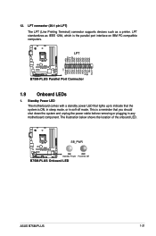
... system and unplug the power cable before removing or plugging in soft-off mode. SB_PWR B75M-PLUS ON OFF Standby Power Powered Off B75M-PLUS Onboard LED ASUS B75M-PLUS 1-21 LPT standardizes as a printer. LPT B75M-PLUS B75M-PLUS Parallel Port Connector 1.9 Onboard LEDs 1. The illustration below shows the location of the onboard... interface on IBM PC-compatible computers. LPT connector (26-1 pin LPT) The LPT (Line Printing Terminal) connector supports devices such as IEEE 1284, which is a reminder that the system is ON, in sleep mode, or in any motherboard component.
... system and unplug the power cable before removing or plugging in soft-off mode. SB_PWR B75M-PLUS ON OFF Standby Power Powered Off B75M-PLUS Onboard LED ASUS B75M-PLUS 1-21 LPT standardizes as a printer. LPT B75M-PLUS B75M-PLUS Parallel Port Connector 1.9 Onboard LEDs 1. The illustration below shows the location of the onboard... interface on IBM PC-compatible computers. LPT connector (26-1 pin LPT) The LPT (Line Printing Terminal) connector supports devices such as IEEE 1284, which is a reminder that the system is ON, in sleep mode, or in any motherboard component.
B75M-PLUS User's Manual
Page 30
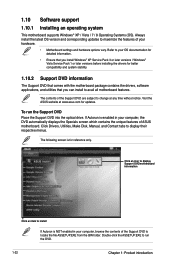
If Autorun is enabled in your computer, browse the contents of the Support DVD are subject to change at www.asus.com for better compatibility and system stability. 1.10.2 Support DVD information The Support DVD that comes with the motherboard package contains the drivers, software applications, and utilities ...• Ensure that you can install to display their respective menus. Click an icon to display Support DVD/motherboard information Click an item to maximize the features of ASUS motherboard. Double-click the ASSETUP.EXE to locate the file ASSETUP.EXE from the BIN folder. The...
If Autorun is enabled in your computer, browse the contents of the Support DVD are subject to change at www.asus.com for better compatibility and system stability. 1.10.2 Support DVD information The Support DVD that comes with the motherboard package contains the drivers, software applications, and utilities ...• Ensure that you can install to display their respective menus. Click an icon to display Support DVD/motherboard information Click an item to maximize the features of ASUS motherboard. Double-click the ASSETUP.EXE to locate the file ASSETUP.EXE from the BIN folder. The...
B75M-PLUS User's Manual
Page 32
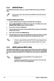
...B75MPLUS.CAP. • The BIOS file in the support DVD may not be the latest version. Enter the Advanced Mode of the BIOS setup program. Press to switch to the Drive field. 4. Download the latest BIOS file from the ASUS website at www.asus.com. 2-2 Chapter 2: Getting started Press the ... a corrupted BIOS file using this utility, download the latest BIOS file from the ASUS website at www.asus.com. Insert the USB flash disk that contains the updated BIOS file. • Before using the motherboard support DVD or a USB flash drive that contains the latest BIOS file to perform the...
...B75MPLUS.CAP. • The BIOS file in the support DVD may not be the latest version. Enter the Advanced Mode of the BIOS setup program. Press to switch to the Drive field. 4. Download the latest BIOS file from the ASUS website at www.asus.com. 2-2 Chapter 2: Getting started Press the ... a corrupted BIOS file using this utility, download the latest BIOS file from the ASUS website at www.asus.com. Insert the USB flash disk that contains the updated BIOS file. • Before using the motherboard support DVD or a USB flash drive that contains the latest BIOS file to perform the...
B75M-PLUS User's Manual
Page 33
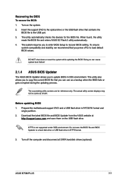
... in FAT32/16 format and single partition. 2. Before updating BIOS 1. Download the latest BIOS file and BIOS Updater from the ASUS website at http://support.asus.com and save the BIOS file and BIOS Updater to load default BIOS values. Recovering the BIOS To recover the BIOS: 1.... 2. The actual utility screen displays may not be same as a backup when the BIOS fails or gets corrupted during the updating process. ASUS B75M-PLUS 2-3 Turn on the USB flash drive. The utility automatically checks the devices for reference only. To ensure system compatibility and stability, we ...
... in FAT32/16 format and single partition. 2. Before updating BIOS 1. Download the latest BIOS file and BIOS Updater from the ASUS website at http://support.asus.com and save the BIOS file and BIOS Updater to load default BIOS values. Recovering the BIOS To recover the BIOS: 1.... 2. The actual utility screen displays may not be same as a backup when the BIOS fails or gets corrupted during the updating process. ASUS B75M-PLUS 2-3 Turn on the USB flash drive. The utility automatically checks the devices for reference only. To ensure system compatibility and stability, we ...
B75M-PLUS User's Manual
Page 34
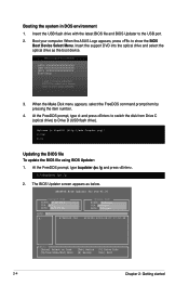
... drive) to show the BIOS Boot Device Select Menu. ASUSTek BIOS Updater for DOS V1.30 BOARD: B75M-PLUS VER: 5011 DATE: 08/07/2011 B75MPLUS.CAP 4194304 2012-08-07 17:30:48 2-4 Chapter 2:... Getting started Updating the BIOS file To update the BIOS file using BIOS Updater: 1. Insert the support DVD into the optical drive and select the optical drive as below. At the FreeDOS prompt, type bupdater /...pc /g and press . 2. When the ASUS Logo appears, press to Drive D (USB flash drive). When the Make Disk menu appears, select the...
... drive) to show the BIOS Boot Device Select Menu. ASUSTek BIOS Updater for DOS V1.30 BOARD: B75M-PLUS VER: 5011 DATE: 08/07/2011 B75MPLUS.CAP 4194304 2012-08-07 17:30:48 2-4 Chapter 2:... Getting started Updating the BIOS file To update the BIOS file using BIOS Updater: 1. Insert the support DVD into the optical drive and select the optical drive as below. At the FreeDOS prompt, type bupdater /...pc /g and press . 2. When the ASUS Logo appears, press to Drive D (USB flash drive). When the Make Disk menu appears, select the...
B75M-PLUS User's Manual
Page 42
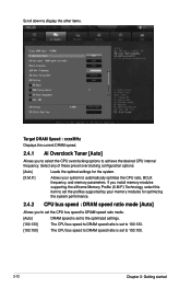
If you install memory modules supporting the eXtreme Memory Profile (X.M.P.) Technology, select this item to set to achieve the desired CPU internal frequency. Scroll down to display the other items. Target ... bus speed to DRAM speed ratio is set to 100:133. [100:100] The CPU bus speed to DRAM speed ratio is set the profiles supported by your memory modules for the system. [X.M.P.] Allows your system to automatically optimize the CPU ratio, BCLK frequency, and memory parameters.
If you install memory modules supporting the eXtreme Memory Profile (X.M.P.) Technology, select this item to set to achieve the desired CPU internal frequency. Scroll down to display the other items. Target ... bus speed to DRAM speed ratio is set to 100:133. [100:100] The CPU bus speed to DRAM speed ratio is set the profiles supported by your memory modules for the system. [X.M.P.] Allows your system to automatically optimize the CPU ratio, BCLK frequency, and memory parameters.


