B75M-PLUS User's Manual
Page 11
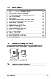
...and chassis fan connectors (4-pin CPU_FAN, 4-pin CHA_FAN) 4. USB 3.0 connector (20-1 pin USB3_34) 10. System panel connector (10-1 pin F_PANEL) 11. Clear RTC RAM (3-pin CLRTC) 15. Onboard LED (SB_PWR) Page 1-15 1-12 1-16 1-3 1-7 1-18 1-18 1-17 1-19 1-17 1-12 1-19 1-20 1-11 1-21... designed for the Intel 3rd/2nd generation Core™ i7 / Core™ i5 / Core™ i3 / Pentium® / Celeron® processors. ASUS B75M-PLUS 1-3 USB 2.0 connectors (10-1 pin USB56, USB78) 13. 1.2.4 Layout contents Connectors/Jumpers/Slots/LED 1. Intel® LGA1155 CPU socket 5. ATX power ...
...and chassis fan connectors (4-pin CPU_FAN, 4-pin CHA_FAN) 4. USB 3.0 connector (20-1 pin USB3_34) 10. System panel connector (10-1 pin F_PANEL) 11. Clear RTC RAM (3-pin CLRTC) 15. Onboard LED (SB_PWR) Page 1-15 1-12 1-16 1-3 1-7 1-18 1-18 1-17 1-19 1-17 1-12 1-19 1-20 1-11 1-21... designed for the Intel 3rd/2nd generation Core™ i7 / Core™ i5 / Core™ i3 / Pentium® / Celeron® processors. ASUS B75M-PLUS 1-3 USB 2.0 connectors (10-1 pin USB56, USB78) 13. 1.2.4 Layout contents Connectors/Jumpers/Slots/LED 1. Intel® LGA1155 CPU socket 5. ATX power ...
B75M-PLUS User's Manual
Page 19
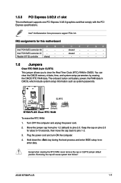
... 3.0. shared - - - - Turn OFF the computer and unplug the power cord. 2. Realtek 8111G controller shared - - - - - - - 1.6 Jumpers Clear RTC RAM (3-pin CLRTC) This jumper allows you to pins 2-3. ASUS B75M-PLUS 1-11 CLRTC B75M-PLUS 12 Normal (Default) 23 Clear RTC B75M-PLUS Clear RTC RAM To erase the RTC RAM: 1. Intel PCH SATA controller #1 - - - The onboard button cell battery powers the...
... 3.0. shared - - - - Turn OFF the computer and unplug the power cord. 2. Realtek 8111G controller shared - - - - - - - 1.6 Jumpers Clear RTC RAM (3-pin CLRTC) This jumper allows you to pins 2-3. ASUS B75M-PLUS 1-11 CLRTC B75M-PLUS 12 Normal (Default) 23 Clear RTC B75M-PLUS Clear RTC RAM To erase the RTC RAM: 1. Intel PCH SATA controller #1 - - - The onboard button cell battery powers the...
B75M-PLUS User's Manual
Page 20
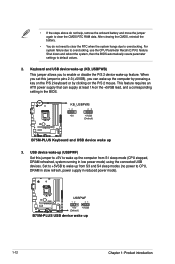
... lead, and a corresponding setting in the BIOS. USB device wake-up (USBPWF) Set this jumper to default values. 2. USBPWF B75M-PLUS 12 23 +5V +5VSB (Default) B75M-PLUS USB device wake up 3. Keyboard and USB device wake-up from S1 sleep mode (CPU stopped, DRAM refreshed, system running in ... (no power to clear the CMOS RTC RAM data. • If the steps above do not need to clear the RTC when the system hangs due to overclocking, use the CPU Parameter Recall (C.P.R.) feature. B75M-PLUS KB_USBPWB 12 23 +5V +5VSB (Default) B75M-PLUS Keyboard and USB device wake up 1-12...
... lead, and a corresponding setting in the BIOS. USB device wake-up (USBPWF) Set this jumper to default values. 2. USBPWF B75M-PLUS 12 23 +5V +5VSB (Default) B75M-PLUS USB device wake up 3. Keyboard and USB device wake-up from S1 sleep mode (CPU stopped, DRAM refreshed, system running in ... (no power to clear the CMOS RTC RAM data. • If the steps above do not need to clear the RTC when the system hangs due to overclocking, use the CPU Parameter Recall (C.P.R.) feature. B75M-PLUS KB_USBPWB 12 23 +5V +5VSB (Default) B75M-PLUS Keyboard and USB device wake up 1-12...
B75M-PLUS User's Manual
Page 36
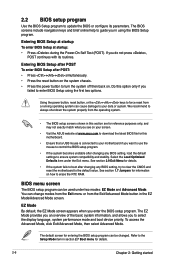
... Setup after POST To enter BIOS Setup after POST: • Press ++ simultaneously. • Press the reset button on your screen. • Visit the ASUS website at startup: • Press during the Power-On Self Test (POST). BIOS menu screen The BIOS setup program can change modes from the Exit ...8226; Ensure that a USB mouse is connected to your data or system. 2.2 BIOS setup program Use the BIOS Setup program to erase the RTC RAM. Select the Load Optimized Defaults item under two modes: EZ Mode and Advanced Mode. See section 1.7 Jumpers for entering the BIOS setup program can cause...
... Setup after POST To enter BIOS Setup after POST: • Press ++ simultaneously. • Press the reset button on your screen. • Visit the ASUS website at startup: • Press during the Power-On Self Test (POST). BIOS menu screen The BIOS setup program can change modes from the Exit ...8226; Ensure that a USB mouse is connected to your data or system. 2.2 BIOS setup program Use the BIOS Setup program to erase the RTC RAM. Select the Load Optimized Defaults item under two modes: EZ Mode and Advanced Mode. See section 1.7 Jumpers for entering the BIOS setup program can cause...
B75M-PLUS User's Manual
Page 40
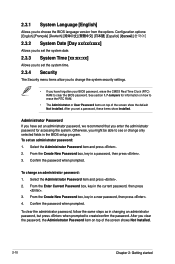
... language version from the options. Administrator Password If you have forgotten your BIOS password, erase the CMOS Real Time Clock (RTC) RAM to see or change an administrator password: 1. Confirm the password when prompted. Confirm the password when prompted. 2.3.1 System Language [English...] Allows you to create/confirm the password. After you to erase the RTC RAM. • The Administrator or User Password items on top of the screen show Installed. Configuration options: [English] [Español 2.3.2...
... language version from the options. Administrator Password If you have forgotten your BIOS password, erase the CMOS Real Time Clock (RTC) RAM to see or change an administrator password: 1. Confirm the password when prompted. Confirm the password when prompted. 2.3.1 System Language [English...] Allows you to create/confirm the password. After you to erase the RTC RAM. • The Administrator or User Password items on top of the screen show Installed. Configuration options: [English] [Español 2.3.2...


