B75M-PLUS User's Manual
Page 6
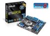
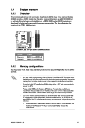
B75M-PLUS specifications summary CPU Chipset Memory Graphics ...- Supports DVI-D with max. Package contents Check your motherboard package for the following items. Motherboard Cables Accessories Application DVD Documentation ASUS B75M-PLUS motherboard 1 x Serial ATA 6.0 Gb/s cable 1 x Serial ATA 3.0 Gb/s cable 1 x I/O Shield Support DVD ...2000/1800MHz frequency. *** Intel® 3rd Generation Core processors support DDR3 1600Mhz and higher memory frequency. **** Refer to www.asus.com for reference only. Supports D-Sub with max.resolution of 1 GB 1 x PCI Express 3.0*/2.0 x16 slot 1 x...
B75M-PLUS specifications summary CPU Chipset Memory Graphics ...- Supports DVI-D with max. Package contents Check your motherboard package for the following items. Motherboard Cables Accessories Application DVD Documentation ASUS B75M-PLUS motherboard 1 x Serial ATA 6.0 Gb/s cable 1 x Serial ATA 3.0 Gb/s cable 1 x I/O Shield Support DVD ...2000/1800MHz frequency. *** Intel® 3rd Generation Core processors support DDR3 1600Mhz and higher memory frequency. **** Refer to www.asus.com for reference only. Supports D-Sub with max.resolution of 1 GB 1 x PCI Express 3.0*/2.0 x16 slot 1 x...
B75M-PLUS User's Manual
Page 9
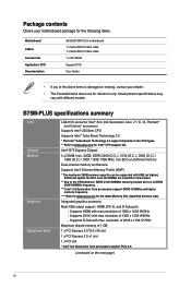
.... 1.2 Motherboard overview Before you install the motherboard, study the configuration of your chassis to do so can damage the motherboard. Do not overtighten the screws! ASUS B75M-PLUS 1-1 Failure to ensure that you place it on a grounded antistatic pad or in the correct orientation.
.... 1.2 Motherboard overview Before you install the motherboard, study the configuration of your chassis to do so can damage the motherboard. Do not overtighten the screws! ASUS B75M-PLUS 1-1 Failure to ensure that you place it on a grounded antistatic pad or in the correct orientation.
B75M-PLUS User's Manual
Page 11
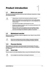
...) 13. Clear RTC RAM (3-pin CLRTC) 15. Front panel audio connector (10-1 pin AAFP) 17. Intel® LGA1155 CPU socket 5. B75M-PLUS B75M-PLUS CPU socket LGA1155 Unplug all power cables before installing the CPU. ASUS B75M-PLUS 1-3 CPU and chassis fan connectors (4-pin CPU_FAN, 4-pin CHA_FAN) 4. Intel® B75 Serial ATA 6.0Gb/s connector (7-pin SATA6G_1 [gray...
...) 13. Clear RTC RAM (3-pin CLRTC) 15. Front panel audio connector (10-1 pin AAFP) 17. Intel® LGA1155 CPU socket 5. B75M-PLUS B75M-PLUS CPU socket LGA1155 Unplug all power cables before installing the CPU. ASUS B75M-PLUS 1-3 CPU and chassis fan connectors (4-pin CPU_FAN, 4-pin CHA_FAN) 4. Intel® B75 Serial ATA 6.0Gb/s connector (7-pin SATA6G_1 [gray...

B75M-PLUS User's Manual
Page 13
4 C A B 5 1.3.2 CPU heatsink and fan assembly installation Apply the Thermal Interface Material to the CPU heatsink and CPU before you install the heatsink and fan if necessary. ASUS B75M-PLUS 1-5
4 C A B 5 1.3.2 CPU heatsink and fan assembly installation Apply the Thermal Interface Material to the CPU heatsink and CPU before you install the heatsink and fan if necessary. ASUS B75M-PLUS 1-5
B75M-PLUS User's Manual
Page 15
... unbuffered non-ECC DDR3 DIMMs into the DIMM sockets. • You may install varying memory sizes in Channel A and Channel B. Check with less power consumption. ASUS B75M-PLUS 1-7 The figure illustrates the location of the lower-sized channel for single-channel operation. • According to Intel CP specification, DIMM voltage below 1.65V is...
... unbuffered non-ECC DDR3 DIMMs into the DIMM sockets. • You may install varying memory sizes in Channel A and Channel B. Check with less power consumption. ASUS B75M-PLUS 1-7 The figure illustrates the location of the lower-sized channel for single-channel operation. • According to Intel CP specification, DIMM voltage below 1.65V is...
B75M-PLUS User's Manual
Page 19
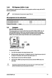
Intel PCH SATA controller #1 - - - Plug the power cord and turn ON the computer. 4. Removing the cap will cause system boot failure! ASUS B75M-PLUS 1-11 shared - - - - Realtek 8111G controller shared - - - - - - - 1.6 Jumpers Clear RTC RAM (3-pin CLRTC) This jumper allows you to pins 1-2. 3. Move ...the CMOS RTC RAM data. Turn OFF the computer and unplug the power cord. 2. shared - - - - CLRTC B75M-PLUS 12 Normal (Default) 23 Clear RTC B75M-PLUS Clear RTC RAM To erase the RTC RAM: 1. Hold down the key during the boot process and enter BIOS setup to...
Intel PCH SATA controller #1 - - - Plug the power cord and turn ON the computer. 4. Removing the cap will cause system boot failure! ASUS B75M-PLUS 1-11 shared - - - - Realtek 8111G controller shared - - - - - - - 1.6 Jumpers Clear RTC RAM (3-pin CLRTC) This jumper allows you to pins 1-2. 3. Move ...the CMOS RTC RAM data. Turn OFF the computer and unplug the power cord. 2. shared - - - - CLRTC B75M-PLUS 12 Normal (Default) 23 Clear RTC B75M-PLUS Clear RTC RAM To erase the RTC RAM: 1. Hold down the key during the boot process and enter BIOS setup to...

B75M-PLUS User's Manual
Page 21
... port allows Gigabit connection to a headphone or a speaker. In the 4, 6 and 8-channel configurations, the function of this port becomes Front Speaker Out. 6. PS/2 mouse port. ASUS B75M-PLUS 1-13 Microphone port (pink). This port connects to a microphone. This 15-pin port is for each USB port; • The USB device wake-up . •...
... port allows Gigabit connection to a headphone or a speaker. In the 4, 6 and 8-channel configurations, the function of this port becomes Front Speaker Out. 6. PS/2 mouse port. ASUS B75M-PLUS 1-13 Microphone port (pink). This port connects to a microphone. This 15-pin port is for each USB port; • The USB device wake-up . •...
B75M-PLUS User's Manual
Page 23
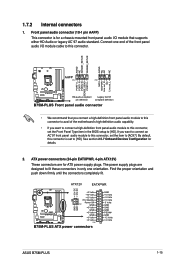
... PIN 1 MIC2 MICPWR Line out_R NC Line out_L PORT1 L PORT1 R PORT2 R SENSE_SEND PORT2 L B75M-PLUS HD-audio-compliant Legacy AC'97 pin definition compliant definition B75M-PLUS Front panel audio connector • We recommend that supports either HD Audio or legacy AC`97 audio ... DC +12V DC B75M-PLUS GND GND +3 Volts +12 Volts +12 Volts +5V Standby Power OK PIN 1 GND +5 Volts GND +5 Volts GND +3 Volts +3 Volts PIN 1 B75M-PLUS ATX power connectors GND +5 Volts +5 Volts +5 Volts -5 Volts GND GND GND PSON# GND -12 Volts +3 Volts ASUS B75M-PLUS 1-15 1.7.2 Internal ...
... PIN 1 MIC2 MICPWR Line out_R NC Line out_L PORT1 L PORT1 R PORT2 R SENSE_SEND PORT2 L B75M-PLUS HD-audio-compliant Legacy AC'97 pin definition compliant definition B75M-PLUS Front panel audio connector • We recommend that supports either HD Audio or legacy AC`97 audio ... DC +12V DC B75M-PLUS GND GND +3 Volts +12 Volts +12 Volts +5V Standby Power OK PIN 1 GND +5 Volts GND +5 Volts GND +3 Volts +3 Volts PIN 1 B75M-PLUS ATX power connectors GND +5 Volts +5 Volts +5 Volts -5 Volts GND GND GND PSON# GND -12 Volts +3 Volts ASUS B75M-PLUS 1-15 1.7.2 Internal ...
B75M-PLUS User's Manual
Page 25
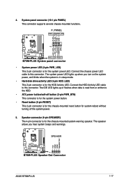
Connect the chassis power LED cable to this connector. SPEAKER B75M-PLUS PIN 1 B75M-PLUS Speaker Out Connector +5V GND GND Speaker Out ASUS B75M-PLUS 1-17 The IDE LED lights up when you hear system beeps and warnings. Speaker connector (4-pin SPEAKER) The 4-pin connector is for the chassis-mounted ...
Connect the chassis power LED cable to this connector. SPEAKER B75M-PLUS PIN 1 B75M-PLUS Speaker Out Connector +5V GND GND Speaker Out ASUS B75M-PLUS 1-17 The IDE LED lights up when you hear system beeps and warnings. Speaker connector (4-pin SPEAKER) The 4-pin connector is for the chassis-mounted ...
B75M-PLUS User's Manual
Page 27
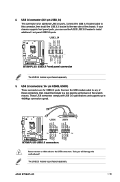
...USB connectors. Doing so will damage the motherboard! ASUS B75M-PLUS 1-19 USB56 USB78 USB+5V USB_P5USB_P5+ GND NC USB+5V USB_P7USB_P7+ GND NC USB+5V USB_P6USB_P6+ GND USB+5V USB_P8USB_P8+ GND B75M-PLUS PIN 1 PIN 1 PIN 1 B75M-PLUS USB2.0 connectors Never connect a 1394 cable to...8. USB 3.0 connector (20-1 pin USB3_34) This connector is purchased separately. The USB 2.0 module is for USB 2.0 ports. Vbus B75M-PLUS PIN 1 B75M-PLUS USB3.0 Front panel connector The USB 3.0 module is purchased separately. 9. Connect the USB 3.0 bracket cable to this connector, then install ...
...USB connectors. Doing so will damage the motherboard! ASUS B75M-PLUS 1-19 USB56 USB78 USB+5V USB_P5USB_P5+ GND NC USB+5V USB_P7USB_P7+ GND NC USB+5V USB_P6USB_P6+ GND USB+5V USB_P8USB_P8+ GND B75M-PLUS PIN 1 PIN 1 PIN 1 B75M-PLUS USB2.0 connectors Never connect a 1394 cable to...8. USB 3.0 connector (20-1 pin USB3_34) This connector is purchased separately. The USB 2.0 module is for USB 2.0 ports. Vbus B75M-PLUS PIN 1 B75M-PLUS USB3.0 Front panel connector The USB 3.0 module is purchased separately. 9. Connect the USB 3.0 bracket cable to this connector, then install ...
B75M-PLUS User's Manual
Page 29
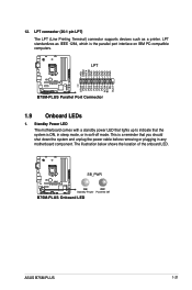
... B75M-PLUS ON OFF Standby Power Powered Off B75M-PLUS Onboard LED ASUS B75M-PLUS 1-21 Standby Power LED The motherboard comes with a standby power LED that lights up to indicate that the system is a reminder that you should shut down the system and unplug the power cable before removing or plugging in soft-off mode. LPT B75M-PLUS B75M-PLUS...
... B75M-PLUS ON OFF Standby Power Powered Off B75M-PLUS Onboard LED ASUS B75M-PLUS 1-21 Standby Power LED The motherboard comes with a standby power LED that lights up to indicate that the system is a reminder that you should shut down the system and unplug the power cable before removing or plugging in soft-off mode. LPT B75M-PLUS B75M-PLUS...
B75M-PLUS User's Manual
Page 31
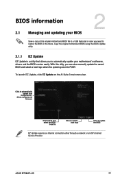
ASUS B75M-PLUS 2-1 Click to automatically update your motherboard's driver, software and firmware Click to find and select the BIOS from file Click to select a boot logo Click ... update the BIOS EZ Update requires an Internet connection either through a network or an ISP (Internet Service Provider. Copy the original motherboard BIOS using the ASUS Update utility. 2.1.1 EZ Update EZ Update is a utility that allows you can also manually update the saved BIOS and select a boot logo when the system...
ASUS B75M-PLUS 2-1 Click to automatically update your motherboard's driver, software and firmware Click to find and select the BIOS from file Click to select a boot logo Click ... update the BIOS EZ Update requires an Internet connection either through a network or an ISP (Internet Service Provider. Copy the original motherboard BIOS using the ASUS Update utility. 2.1.1 EZ Update EZ Update is a utility that allows you can also manually update the saved BIOS and select a boot logo when the system...
B75M-PLUS User's Manual
Page 33
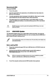
... only. When found, the utility reads the BIOS file and enters ASUS EZ Flash 2 utility automatically. 4. Doing so can use as shown. Prepare the motherboard support DVD and a USB flash drive in NTFS format. 3. ASUS B75M-PLUS 2-3 Turn on the USB flash drive. Download the latest BIOS file... and BIOS Updater from the ASUS website at http://support.asus.com and save the BIOS file and BIOS Updater to the USB port. 3. ...
... only. When found, the utility reads the BIOS file and enters ASUS EZ Flash 2 utility automatically. 4. Doing so can use as shown. Prepare the motherboard support DVD and a USB flash drive in NTFS format. 3. ASUS B75M-PLUS 2-3 Turn on the USB flash drive. Download the latest BIOS file... and BIOS Updater from the ASUS website at http://support.asus.com and save the BIOS file and BIOS Updater to the USB port. 3. ...
B75M-PLUS User's Manual
Page 35
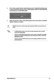
..., press to select the BIOS file and press . Select Yes and press . Select the Load Optimized Defaults item under the Exit menu. Restart your computer. ASUS B75M-PLUS 2-5 Press to switch between screen fields and use the keys to exit BIOS Updater. DO NOT shut down or reset the system while updating the...
..., press to select the BIOS file and press . Select Yes and press . Select the Load Optimized Defaults item under the Exit menu. Restart your computer. ASUS B75M-PLUS 2-5 Press to switch between screen fields and use the keys to exit BIOS Updater. DO NOT shut down or reset the system while updating the...
B75M-PLUS User's Manual
Page 37
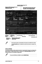
To access the EZ Mode, click Exit, then select ASUS EZ Mode. Selects the display language of the BIOS setup program Displays the CPU/motherboard temperature, CPU/5V/3.3V/12V voltage output, CPU/chassis fan ... example of the selected mode on the right hand side Loads optimized default ASUS Optimal mode • The boot device options vary depending on the devices you installed to the system. • The Boot Menu(F8) button is available only when the boot device is installed to configure the BIOS settings. ASUS B75M-PLUS 2-7
To access the EZ Mode, click Exit, then select ASUS EZ Mode. Selects the display language of the BIOS setup program Displays the CPU/motherboard temperature, CPU/5V/3.3V/12V voltage output, CPU/chassis fan ... example of the selected mode on the right hand side Loads optimized default ASUS Optimal mode • The boot device options vary depending on the devices you installed to the system. • The Boot Menu(F8) button is available only when the boot device is installed to configure the BIOS settings. ASUS B75M-PLUS 2-7
B75M-PLUS User's Manual
Page 39
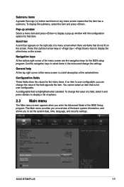
... select an item that do not fit on the screen. The Main menu provides you to set the system date, time, language, and security settings. ASUS B75M-PLUS 2-9 Use the navigation keys to display a list of options. 2.3 Main menu The Main menu screen appears when you can change the settings. Press the Up...
... select an item that do not fit on the screen. The Main menu provides you to set the system date, time, language, and security settings. ASUS B75M-PLUS 2-9 Use the navigation keys to display a list of options. 2.3 Main menu The Main menu screen appears when you can change the settings. Press the Up...
B75M-PLUS User's Manual
Page 41
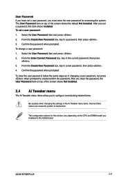
ASUS B75M-PLUS 2-11 To set a user password: 1. Select the User Password item and press . 2. To change a user password: 1. The configuration options for accessing the system. Confirm the ...
ASUS B75M-PLUS 2-11 To set a user password: 1. Select the User Password item and press . 2. To change a user password: 1. The configuration options for accessing the system. Confirm the ...
B75M-PLUS User's Manual
Page 43
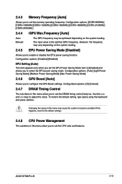
.... Changing the values in this menu may be optimized depending on the system loading. 2.4.5 EPU Power Saving Mode [Disabled] Allows you to adjust the value. ASUS B75M-PLUS 2-13 Configuration options: [Ok] [Cancel] 2.4.7 DRAM Timing Control The sub-items in this menu allow you to set the memory operating frequency. If this happens...
.... Changing the values in this menu may be optimized depending on the system loading. 2.4.5 EPU Power Saving Mode [Disabled] Allows you to adjust the value. ASUS B75M-PLUS 2-13 Configuration options: [Ok] [Cancel] 2.4.7 DRAM Timing Control The sub-items in this menu allow you to set the memory operating frequency. If this happens...
B75M-PLUS User's Manual
Page 45
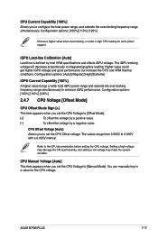
Setting a high voltage may damage the CPU permanently, and setting a low voltage may make the system unstable. ASUS B75M-PLUS 2-15 iGPU Load-line Calibration [Auto] Load-line is defined by a negative value. The iGPU working voltage will decrease proportionally to 0.635V with a 0.005V interval. ...
Setting a high voltage may damage the CPU permanently, and setting a low voltage may make the system unstable. ASUS B75M-PLUS 2-15 iGPU Load-line Calibration [Auto] Load-line is defined by a negative value. The iGPU working voltage will decrease proportionally to 0.635V with a 0.005V interval. ...
B75M-PLUS User's Manual
Page 47
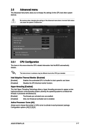
... activated core are enabled. [Disabled] Only one thread per activated core is enabled. 2.5 Advanced menu The Advanced menu items allow you installed. Configuration options: [All] [1] [2] [3] ASUS B75M-PLUS 2-17 Hyper-threading [Enabled] The Intel Hyper-Threading Technology allows a hyper-threading processor to appear as two logical processors to the operating system, allowing the...
... activated core are enabled. [Disabled] Only one thread per activated core is enabled. 2.5 Advanced menu The Advanced menu items allow you installed. Configuration options: [All] [1] [2] [3] ASUS B75M-PLUS 2-17 Hyper-threading [Enabled] The Intel Hyper-Threading Technology allows a hyper-threading processor to appear as two logical processors to the operating system, allowing the...


