
User Guide
Page 6
...'s instructions, may not cause harmful interference, and • This device must accept any interference received including interference that interference will not occur in a particular installation. If this equipment. The use of the monitor to the graphics card is connected. • Consult the dealer or an experienced radio/TV technician for connection of shielded cables for help. This equipment has been tested...
...'s instructions, may not cause harmful interference, and • This device must accept any interference received including interference that interference will not occur in a particular installation. If this equipment. The use of the monitor to the graphics card is connected. • Consult the dealer or an experienced radio/TV technician for connection of shielded cables for help. This equipment has been tested...
User Guide
Page 9
.... ASUS websites The ASUS websites worldwide provide updated information for product and software updates. 1 . ix ASUS NCL-DS1R1 motherboard user guide This manual contains detailed information about the ASUS NCL-DS1R1 motherboard. 2 . N O T E : Tips and information to complete a task. References Refer to the following symbols used throughout this manual. Refer to set up and use the proprietary ASUS server management utility. 3. ASUS Server Web-based Management (ASWM) user guide This manual tells how to the ASUS contact information. W A R N I M P O R T A N T : Instructions...
.... ASUS websites The ASUS websites worldwide provide updated information for product and software updates. 1 . ix ASUS NCL-DS1R1 motherboard user guide This manual contains detailed information about the ASUS NCL-DS1R1 motherboard. 2 . N O T E : Tips and information to complete a task. References Refer to the following symbols used throughout this manual. Refer to set up and use the proprietary ASUS server management utility. 3. ASUS Server Web-based Management (ASWM) user guide This manual tells how to the ASUS contact information. W A R N I M P O R T A N T : Instructions...
User Guide
Page 13
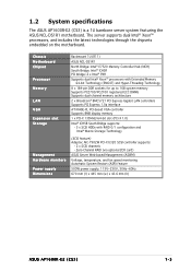
... optional ZCR card) ASUS Server Web-based Management (ASWM) Voltage, temperature, and fan speed monitoring Automatic System Restart (ASR) feature 500W power supply, 115V~230V, 50Hz~60Hz 670 mm (l) x 445 mm (w) x 43.6 mm (h) ASUS AP1600R-E2 (CS3) 1-3 Chassis Motherboard Chipset Processor Memory LAN VGA Expansion slot Storage Management Hardware monitors Power supply Dimensions Rackmount 1U (R11) ASUS NCL-DS1R1 North Bridge: Intel® E7520 Memory Controller Hub (MCH) South Bridge: Intel® ICH5R PCI bridge: 2 x Intel® PXH Supports dual...
... optional ZCR card) ASUS Server Web-based Management (ASWM) Voltage, temperature, and fan speed monitoring Automatic System Restart (ASR) feature 500W power supply, 115V~230V, 50Hz~60Hz 670 mm (l) x 445 mm (w) x 43.6 mm (h) ASUS AP1600R-E2 (CS3) 1-3 Chassis Motherboard Chipset Processor Memory LAN VGA Expansion slot Storage Management Hardware monitors Power supply Dimensions Rackmount 1U (R11) ASUS NCL-DS1R1 North Bridge: Intel® E7520 Memory Controller Hub (MCH) South Bridge: Intel® ICH5R PCI bridge: 2 x Intel® PXH Supports dual...
User Guide
Page 33
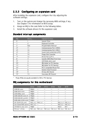
... the expansion card. PCIX slot 1 (64-bit) INTA# INTB# INTC# INTD# REQ# GNT# PIRQC# - - - - - REQ1H GNT1 PXH1_B_0 PXH1_B_1 PXH1_B_2 PXH1_B_3 PXH1_B_0 PXH1_B_0 ASUS AP1600R-E2 (CS3) 2-15 Refer to the card. Install the software drivers for ISA or PCI devices. PIRQB# - - - - - PXH2_A_0 PXH2_A_0 PXH2_A_2 - - - AIC-7902W SCSI contrl. ICH5R USB UHCI contrl. #1 ICH5R USB UHCI contrl.#2 ICH5R USB 2.0 EHCI contrl. Zero-Channel RAID sockets ATI...
... the expansion card. PCIX slot 1 (64-bit) INTA# INTB# INTC# INTD# REQ# GNT# PIRQC# - - - - - REQ1H GNT1 PXH1_B_0 PXH1_B_1 PXH1_B_2 PXH1_B_3 PXH1_B_0 PXH1_B_0 ASUS AP1600R-E2 (CS3) 2-15 Refer to the card. Install the software drivers for ISA or PCI devices. PIRQB# - - - - - PXH2_A_0 PXH2_A_0 PXH2_A_2 - - - AIC-7902W SCSI contrl. ICH5R USB UHCI contrl. #1 ICH5R USB UHCI contrl.#2 ICH5R USB 2.0 EHCI contrl. Zero-Channel RAID sockets ATI...
User Guide
Page 35
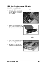
Remove the two screws on Pin 1 the motherboard, and connect one end (with the two screws that you removed earlier. Secure the port with the white tab) of the cable, and set them aside. 3. Locate the SCSI-B connector on the other end (external SCSI port) of the SCSI cable. 2. Insert the external SCSI port into the slot opening on the rear panel. 4. Screws ASUS AP1600R-E2 (CS3) 2-17 2.6.2 Installing the external SCSI cable To install the external SCSI cable: 1.
Remove the two screws on Pin 1 the motherboard, and connect one end (with the two screws that you removed earlier. Secure the port with the white tab) of the cable, and set them aside. 3. Locate the SCSI-B connector on the other end (external SCSI port) of the SCSI cable. 2. Insert the external SCSI port into the slot opening on the rear panel. 4. Screws ASUS AP1600R-E2 (CS3) 2-17 2.6.2 Installing the external SCSI cable To install the external SCSI cable: 1.
User Guide
Page 49
Layout contents Switches and jumpers DIP switch (DSW1) SCSI controller setting (3-pin SCSI_EN1) Clear RTC RAM (CLRTC1) CPU fan pin selection (3-pin FM_CPU1, FM_CPU2) USB device wake-up (3-pin USBPW12, USBPW34) Keyboard power (3-pin KBPWR1) Gigabit LAN1 controller setting (3-pin LAN_EN1) Gigabit LAN2 controller setting (3-pin LAN_EN2) Integrated graphics controller (3-pin VGA_EN1) Force BIOS recovery (3-pin RECOVERY) Page 4-4 4-4 4-5 4-6 4-6 4-7 4-7 4-8 4-8 4-9 Internal connectors Floppy disk drive connector (34-1 pin FLOPPY) IDE connectors (40-1 pin PRI_IDE, SEC_IDE) Serial ATA connectors ...
Layout contents Switches and jumpers DIP switch (DSW1) SCSI controller setting (3-pin SCSI_EN1) Clear RTC RAM (CLRTC1) CPU fan pin selection (3-pin FM_CPU1, FM_CPU2) USB device wake-up (3-pin USBPW12, USBPW34) Keyboard power (3-pin KBPWR1) Gigabit LAN1 controller setting (3-pin LAN_EN1) Gigabit LAN2 controller setting (3-pin LAN_EN2) Integrated graphics controller (3-pin VGA_EN1) Force BIOS recovery (3-pin RECOVERY) Page 4-4 4-4 4-5 4-6 4-6 4-7 4-7 4-8 4-8 4-9 Internal connectors Floppy disk drive connector (34-1 pin FLOPPY) IDE connectors (40-1 pin PRI_IDE, SEC_IDE) Serial ATA connectors ...
User Guide
Page 50
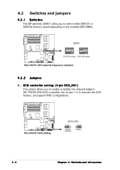
... either DDR333 or DDR266 memory speed depending on the installed DDR DIMMs. DSW1 DDR 333 setting DDR 266 setting NCL-DS1R1 CPU external frequency selection 4.2.2 Jumpers 1 . SCSI controller setting (3-pin SCSI_EN1) This jumper allows you to enable or disable the onboard Adaptec AIC-7902W SCSI U320 controller. Set to pins 1-2 to activate the SCSI feature, and support RAID configurations. ® NCL-DS1R1 NCL-DS1R1 SCSI setting SCSI_EN1 12 23 Enable (Default) Disable 4-4 Chapter 4: Motherboard information
... either DDR333 or DDR266 memory speed depending on the installed DDR DIMMs. DSW1 DDR 333 setting DDR 266 setting NCL-DS1R1 CPU external frequency selection 4.2.2 Jumpers 1 . SCSI controller setting (3-pin SCSI_EN1) This jumper allows you to enable or disable the onboard Adaptec AIC-7902W SCSI U320 controller. Set to pins 1-2 to activate the SCSI feature, and support RAID configurations. ® NCL-DS1R1 NCL-DS1R1 SCSI setting SCSI_EN1 12 23 Enable (Default) Disable 4-4 Chapter 4: Motherboard information
User Guide
Page 53
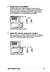
... BIOS. Keyboard power (3-pin KBPWR1) This jumper allows you to enable or disable the keyboard wake-up the computer when you press a key on the keyboard (the default is the Space Bar). Set this jumper to pins 2-3 (+5VSB) to activate the Gigabit LAN1 controller. KBPWR1 1 2 +5V (Default) 2 3 +5VSB ® NCL-DS1R1 NCL-DS1R1 Keyboard power setting 6 . NCL-DS1R1 LAN1_EN setting ® NCL-DS1R1 LAN1_EN1 2 1 Enable (Default) 3 2 Disable ASUS AP1600R-E2 (CS3) 4-7 5. This feature requires an ATX power supply that controls...
... BIOS. Keyboard power (3-pin KBPWR1) This jumper allows you to enable or disable the keyboard wake-up the computer when you press a key on the keyboard (the default is the Space Bar). Set this jumper to pins 2-3 (+5VSB) to activate the Gigabit LAN1 controller. KBPWR1 1 2 +5V (Default) 2 3 +5VSB ® NCL-DS1R1 NCL-DS1R1 Keyboard power setting 6 . NCL-DS1R1 LAN1_EN setting ® NCL-DS1R1 LAN1_EN1 2 1 Enable (Default) 3 2 Disable ASUS AP1600R-E2 (CS3) 4-7 5. This feature requires an ATX power supply that controls...
User Guide
Page 54
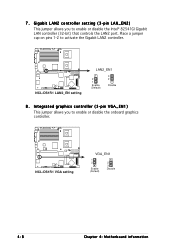
... LAN2 controller setting (3-pin LAN_EN2) This jumper allows you to enable or disable the onboard graphics controller. ® NCL-DS1R1 NCL-DS1R1 VGA setting VGA_EN1 1 2 Enable (Default) 2 3 Disable 4-8 Chapter 4: Motherboard information NCL-DS1R1 LAN2_EN setting ® NCL-DS1R1 LAN2_EN1 2 1 Enable (Default) 3 2 Disable 8 . Place a jumper cap on pins 1-2 to enable or disable the Intel® 82541GI Gigabit LAN controller (32-bit) that controls the LAN2 port. 7 . Integrated graphics controller (3-pin VGA_EN1) This jumper allows you to activate the Gigabit LAN2 controller.
... LAN2 controller setting (3-pin LAN_EN2) This jumper allows you to enable or disable the onboard graphics controller. ® NCL-DS1R1 NCL-DS1R1 VGA setting VGA_EN1 1 2 Enable (Default) 2 3 Disable 4-8 Chapter 4: Motherboard information NCL-DS1R1 LAN2_EN setting ® NCL-DS1R1 LAN2_EN1 2 1 Enable (Default) 3 2 Disable 8 . Place a jumper cap on pins 1-2 to enable or disable the Intel® 82541GI Gigabit LAN controller (32-bit) that controls the LAN2 port. 7 . Integrated graphics controller (3-pin VGA_EN1) This jumper allows you to activate the Gigabit LAN2 controller.
User Guide
Page 56
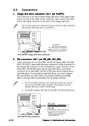
... match the covered hole on the motherboard, a gray connector for an Ultra DMA 100/66 IDE master device (hard disk drive), and a black connector for the provided floppy disk drive (FDD) signal cable. 4.3 Connectors 1 . If you install two hard disk drives, you connect the IDE cable. • Use the 80-conductor IDE cable for Ultra DMA 100/66/33 IDE devices. 4-10 NCL-DS1R1 IDE connectors ® NCL-DS1R1 SEC_IDE PIN 1 PRI_IDE PIN 1 NOTE: Orient...
... match the covered hole on the motherboard, a gray connector for an Ultra DMA 100/66 IDE master device (hard disk drive), and a black connector for the provided floppy disk drive (FDD) signal cable. 4.3 Connectors 1 . If you install two hard disk drives, you connect the IDE cable. • Use the 80-conductor IDE cable for Ultra DMA 100/66/33 IDE devices. 4-10 NCL-DS1R1 IDE connectors ® NCL-DS1R1 SEC_IDE PIN 1 PRI_IDE PIN 1 NOTE: Orient...
User Guide
Page 64
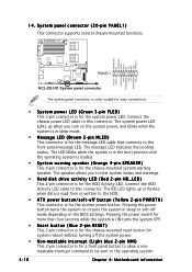
Message LED (Brown 2-pin MLED) This connector is for the chassis-mounted reset button for the message LED cable that connects to the operating system. The speaker allows you turn on the BIOS settings. Reset button (Blue 2-pin RESET) This 2-pin connector is for system reboot without turning off the system power. Hard disk drive activity LED (Red 2-pin HD_LED) This 2-pin connector is for the HDD Activity LED. Non-maskable interrupt (Light blue 2-pin NMI) This 2-pin connector is for a front panel button to allow a nonmaskable interrupt...
Message LED (Brown 2-pin MLED) This connector is for the chassis-mounted reset button for the message LED cable that connects to the operating system. The speaker allows you turn on the BIOS settings. Reset button (Blue 2-pin RESET) This 2-pin connector is for system reboot without turning off the system power. Hard disk drive activity LED (Red 2-pin HD_LED) This 2-pin connector is for the HDD Activity LED. Non-maskable interrupt (Light blue 2-pin NMI) This 2-pin connector is for a front panel button to allow a nonmaskable interrupt...
User Guide
Page 72
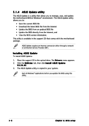
...s menu appears. 2. Click the U t i l i t i e s tab, then click I n s t a l l A S U S U p d a t e V X . X X. 3. ASUS Update requires an Internet connection either through a network or an Internet Service Provider (ISP). Place the support CD in the support CD that allows you to your system. This utility is available in the optical drive. Installing ASUS Update To install ASUS Update: 1. 5.1.4 ASUS Update utility The ASUS Update is a utility that comes with the motherboard package. The ASUS Update utility is copied to manage, save, and update the motherboard BIOS in Windows®...
...s menu appears. 2. Click the U t i l i t i e s tab, then click I n s t a l l A S U S U p d a t e V X . X X. 3. ASUS Update requires an Internet connection either through a network or an Internet Service Provider (ISP). Place the support CD in the support CD that allows you to your system. This utility is available in the optical drive. Installing ASUS Update To install ASUS Update: 1. 5.1.4 ASUS Update utility The ASUS Update is a utility that comes with the motherboard package. The ASUS Update utility is copied to manage, save, and update the motherboard BIOS in Windows®...
User Guide
Page 75
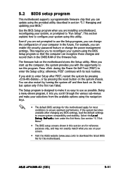
... configure your system using the provided utility described in section "5.1 Managing and updating your selections from the available options using the navigation keys. • The default BIOS settings for this motherboard apply for this motherboard. otherwise, POST continues with the opportunity to make your BIOS." The Setup program is designed to run this program. ASUS AP1600R-E2 (CS3) 5-11 This section explains how to "Run Setup". The firmware hub on . You can change the power management settings...
... configure your system using the provided utility described in section "5.1 Managing and updating your selections from the available options using the navigation keys. • The default BIOS settings for this motherboard apply for this motherboard. otherwise, POST continues with the opportunity to make your BIOS." The Setup program is designed to run this program. ASUS AP1600R-E2 (CS3) 5-11 This section explains how to "Run Setup". The firmware hub on . You can change the power management settings...
User Guide
Page 79
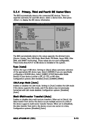
... drive. Configuration options: [Disabled] [Auto] ASUS AP1600R-E2 (CS3) 5-15 There is a separate sub-menu for each IDE device. Configuration options: [Disabled] [Auto] Block (Multi-sector Transfer) [Auto] Enables or disables data multi-sectors transfers. These values are specifically configuring a CD-ROM drive. 5.3.4 Primary, Third and Fourth IDE Master/Slave The BIOS automatically detects the connected IDE devices. Setting to the system. Primary IDE Master Device : Hard Disk Vendor : ST320413A Size : 20.0GB LBA Mode : Supported Block Mode...
... drive. Configuration options: [Disabled] [Auto] ASUS AP1600R-E2 (CS3) 5-15 There is a separate sub-menu for each IDE device. Configuration options: [Disabled] [Auto] Block (Multi-sector Transfer) [Auto] Enables or disables data multi-sectors transfers. These values are specifically configuring a CD-ROM drive. 5.3.4 Primary, Third and Fourth IDE Master/Slave The BIOS automatically detects the connected IDE devices. Setting to the system. Primary IDE Master Device : Hard Disk Vendor : ST320413A Size : 20.0GB LBA Mode : Supported Block Mode...
User Guide
Page 81
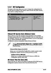
...] Configure S-ATA as RAID sets. Onboard IDE Operate Mode [Enhanced Mode] Allows selection of the IDE operation mode depending on the installed operating system (OS). Set to [Enhanced Mode]. A T A a s R A I D appear only when you set or change the configurations for detecting ATA/ATAPI devices. Configuration options: [0] [5] [10] [15] [20] [25] [30] [35] ASUS AP1600R-E2 (CS3) 5-17 5.3.5 IDE Configuration The items in this menu allow you to native mode. Enhanced Mode Support On [S-ATA] Allows you to set Serial...
...] Configure S-ATA as RAID sets. Onboard IDE Operate Mode [Enhanced Mode] Allows selection of the IDE operation mode depending on the installed operating system (OS). Set to [Enhanced Mode]. A T A a s R A I D appear only when you set or change the configurations for detecting ATA/ATAPI devices. Configuration options: [0] [5] [10] [15] [20] [25] [30] [35] ASUS AP1600R-E2 (CS3) 5-17 5.3.5 IDE Configuration The items in this menu allow you to native mode. Enhanced Mode Support On [S-ATA] Allows you to set Serial...
User Guide
Page 84
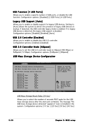
...none is disabled. Select Screen Select Item +- Configuration options: [Disabled] [2 USB Ports] [4 USB Ports] Legacy USB Support [Auto] Allows you to enable or disable support for the USB mass storage device after start unit command. Setting to [Auto] allows the system to enable a specific number of USB ports, or disable the USB function. If no legacy USB device is detected, the legacy USB support is installed in the system. Configuration options: [FullSpeed ] [HiSpeed] USB Mass Storage Device Configuration USB Mass Storage Device Configuration USB Mass Storage Reset Delay [20...
...none is disabled. Select Screen Select Item +- Configuration options: [Disabled] [2 USB Ports] [4 USB Ports] Legacy USB Support [Auto] Allows you to enable or disable support for the USB mass storage device after start unit command. Setting to [Auto] allows the system to enable a specific number of USB ports, or disable the USB function. If no legacy USB device is detected, the legacy USB support is installed in the system. Configuration options: [FullSpeed ] [HiSpeed] USB Mass Storage Device Configuration USB Mass Storage Device Configuration USB Mass Storage Reset Delay [20...
User Guide
Page 86
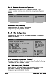
...CPUID Value Limit: [Enabled] [Disabled] Execute Disable Function [Enabled] Enhance C1 Control [Disabled] CPU Internal Thermal Control [Auto] Intel(R) SpeedStep Tech [Automatic] Sets the ratio between CPU Core Clock and the FSB Frequency. Select Screen Select Item +- NOTE: If an invalid ratio is set in this menu show the CPU-related information that the BIOS automatically detects. Configure Remote Access type and parameters Remote Access [Disabled] Select Remote Access type. Configuration options: [Disabled] [Enabled] 5-22 Chapter 5: BIOS setup Change Option F1 General Help F10...
...CPUID Value Limit: [Enabled] [Disabled] Execute Disable Function [Enabled] Enhance C1 Control [Disabled] CPU Internal Thermal Control [Auto] Intel(R) SpeedStep Tech [Automatic] Sets the ratio between CPU Core Clock and the FSB Frequency. Select Screen Select Item +- NOTE: If an invalid ratio is set in this menu show the CPU-related information that the BIOS automatically detects. Configure Remote Access type and parameters Remote Access [Disabled] Select Remote Access type. Configuration options: [Disabled] [Enabled] 5-22 Chapter 5: BIOS setup Change Option F1 General Help F10...
User Guide
Page 92
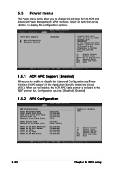
... (ACPI) support in the RSDT pointer list. Configuration options: [Disabled] [Enabled] 5.5.2 APM Configuration APM Configuration Power Management/APM Video Power Down Mode Hard Disk Power Down Mode Suspend Time Out Throttle Slow Clock Ratio Power Button Mode Restore on AC Power Loss Power On By PS/2 Keyboard Power On By PS/2 Mouse Power On Ring Power On By PME# Power On By RTC Alarm [Enabled] [Disabled] [Disabled] [Disabled] [50%] [On/Off] [Last State] [Disabled] [Disabled] [Disabled] [Disabled] [Disabled] Enable or disable APM. 5-28 Chapter 5: BIOS setup Do not change the settings for...
... (ACPI) support in the RSDT pointer list. Configuration options: [Disabled] [Enabled] 5.5.2 APM Configuration APM Configuration Power Management/APM Video Power Down Mode Hard Disk Power Down Mode Suspend Time Out Throttle Slow Clock Ratio Power Button Mode Restore on AC Power Loss Power On By PS/2 Keyboard Power On By PS/2 Mouse Power On Ring Power On By PME# Power On By RTC Alarm [Enabled] [Disabled] [Disabled] [Disabled] [50%] [On/Off] [Last State] [Disabled] [Disabled] [Disabled] [Disabled] [Disabled] Enable or disable APM. 5-28 Chapter 5: BIOS setup Do not change the settings for...
User Guide
Page 100
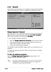
... to disabled password. again to erase the RTC RAM. 5-36 Chapter 5: BIOS setup After you set or change the supervisor password. To set your BIOS password, you can clear clear it by erasing the CMOS Real Time Clock (RTC) RAM. The message "Password Uninstalled" appears. Security Settings Supervisor Password : Not Installed User Password : Not Installed Change Supervisor Password to change a supervisor password: 1. The message "Password Installed" appears after you successfully set or change password. To change the system security settings. See section "2.6 Jumpers...
... to disabled password. again to erase the RTC RAM. 5-36 Chapter 5: BIOS setup After you set or change the supervisor password. To set your BIOS password, you can clear clear it by erasing the CMOS Real Time Clock (RTC) RAM. The message "Password Uninstalled" appears. Security Settings Supervisor Password : Not Installed User Password : Not Installed Change Supervisor Password to change a supervisor password: 1. The message "Password Installed" appears after you successfully set or change password. To change the system security settings. See section "2.6 Jumpers...
User Guide
Page 101
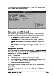
... the Setup items. Configuration options: [No Access] [View Only] [Limited] [Full Access] N o A c c e s s prevents user access to the Setup utility. Confirm the password when prompted. ASUS AP1600R-E2 (CS3) 5-37 F u l l A c c e s s allows viewing and changing all the fields in setting a user password. V i e w O n l y allows access but does not allow you set your password successfully. To set or change the user password. The U s e r P a s s w o r d item on top of at least six letters and/or numbers, then press . 3. The message "Password Installed" appears...
... the Setup items. Configuration options: [No Access] [View Only] [Limited] [Full Access] N o A c c e s s prevents user access to the Setup utility. Confirm the password when prompted. ASUS AP1600R-E2 (CS3) 5-37 F u l l A c c e s s allows viewing and changing all the fields in setting a user password. V i e w O n l y allows access but does not allow you set your password successfully. To set or change the user password. The U s e r P a s s w o r d item on top of at least six letters and/or numbers, then press . 3. The message "Password Installed" appears...


