
Motherboard DIY Troubleshooting Guide
Page 1
Motherboard A7N8X-VM/400 User Guide
Motherboard A7N8X-VM/400 User Guide

Motherboard DIY Troubleshooting Guide
Page 3
Features Contents Notices v Safety information vi About this guide vii A7N8X-VM/400 specification summary viii Chapter 1: Product introduction 1.1 Welcome 1-2 1.2 Package contents 1-2 1.3 Special features 1-2 1.4 Motherboard components 1-4 1.5 Motherboard layout 1-7 1.6 Motherboard installation 1-8 1.6.1 Placement direction 1-8 1.6.2 Screw holes 1-8 1.7 Before you proceed 1-9... BIOS 2-3 2.1.3 Using AFUDOS to update the BIOS 2-4 2.1.4 Using ASUS EZ Flash to update the BIOS 2-5 2.1.5 ASUS Update 2-6 2.2 BIOS Setup program 2-8 2.2.1 BIOS menu bar 2-8 2.2.2 Legend bar 2-9 iii
Features Contents Notices v Safety information vi About this guide vii A7N8X-VM/400 specification summary viii Chapter 1: Product introduction 1.1 Welcome 1-2 1.2 Package contents 1-2 1.3 Special features 1-2 1.4 Motherboard components 1-4 1.5 Motherboard layout 1-7 1.6 Motherboard installation 1-8 1.6.1 Placement direction 1-8 1.6.2 Screw holes 1-8 1.7 Before you proceed 1-9... BIOS 2-3 2.1.3 Using AFUDOS to update the BIOS 2-4 2.1.4 Using ASUS EZ Flash to update the BIOS 2-5 2.1.5 ASUS Update 2-6 2.2 BIOS Setup program 2-8 2.2.1 BIOS menu bar 2-8 2.2.2 Legend bar 2-9 iii

Motherboard DIY Troubleshooting Guide
Page 12
... floppy drive Bag of fast, reliable computing solution. See details on it, check the items in ASUS A7N8X-VM/400 series support CD 40-pin 80-conductor ribbon cable for UltraDMA133 IDE drives Ribbon cable for buying the ASUS® A7N8X-VM/400 motherboard! 1.1 Welcome! Thank you a powerful and efficient computer platform. Dual-channel DDR memory support With the...
... floppy drive Bag of fast, reliable computing solution. See details on it, check the items in ASUS A7N8X-VM/400 series support CD 40-pin 80-conductor ribbon cable for UltraDMA133 IDE drives Ribbon cable for buying the ASUS® A7N8X-VM/400 motherboard! 1.1 Welcome! Thank you a powerful and efficient computer platform. Dual-channel DDR memory support With the...

Motherboard DIY Troubleshooting Guide
Page 13
... high texture content and scene complexity capabilities. Digital video output support The DVO interface feature of up to 2.12 GB/s. ASUS A7N8X-VM/400 motherboard user guide 1-3 See details on page 2-5. See details on page 1-13. ASUS C.O.P. No need to use a DOS-based utility or boot from a floppy disk. See details on page 2-13. See details...
... high texture content and scene complexity capabilities. Digital video output support The DVO interface feature of up to 2.12 GB/s. ASUS A7N8X-VM/400 motherboard user guide 1-3 See details on page 2-5. See details on page 1-13. ASUS C.O.P. No need to use a DOS-based utility or boot from a floppy disk. See details on page 2-13. See details...

Motherboard DIY Troubleshooting Guide
Page 15
... DIMM) sockets are slotted to 2 GB of DDR SDRAM. This connector is a standby power on the +5V standby lead (+5VSB). 3 CPU socket. ASUS A7N8X-VM/400 motherboard user guide 1-5 This LED acts as a reminder to four UltraDMA133, PIO Modes 0-4 IDE devices. The power supply must have at 800 MB/s with ... AGP slot also supports digital visual interface (DVI) cards for the floppy disk drive. This controller communicates at least 1A on the motherboard. The Northbridge controller is slotted to support PCI, USB, and Fast Ethernet devices. One side of the connector is equipped with the...
... DIMM) sockets are slotted to 2 GB of DDR SDRAM. This connector is a standby power on the +5V standby lead (+5VSB). 3 CPU socket. ASUS A7N8X-VM/400 motherboard user guide 1-5 This LED acts as a reminder to four UltraDMA133, PIO Modes 0-4 IDE devices. The power supply must have at 800 MB/s with ... AGP slot also supports digital visual interface (DVI) cards for the floppy disk drive. This controller communicates at least 1A on the motherboard. The Northbridge controller is slotted to support PCI, USB, and Fast Ethernet devices. One side of the connector is equipped with the...

Motherboard DIY Troubleshooting Guide
Page 17
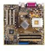
FLOPPY1 24.5cm (9.64in) 1.5 Motherboard layout PS/2 T: Mouse B: Keyboard USB3 USB4 COM1 USBPW34 24.5cm (9.64in) Socket 462 CPU_FAN1 DDR DIMM2 (64/128 bit, 184-pin module) DDR DIMM3 (64/...:Line In Center:Line Out Below:Mic In Realtek RTL8201 AUX1 CD1 U46 nVidia nForce2 IGP CHA_FAN A7N8X-VM Accelerated Graphics Port (AGP8X1) PCI 1 FPAUDIO Audio Codec PCI 2 SPDIF1 PCI 3 23 45 Super I/O CR2032 3V Lithium Cell CMOS Power nVidia MCP CLRTC1 4Mb BIOS CHASSIS1 COM2 USBPW56 GAME1 USB56 PANEL1 ASUS A7N8X-VM/400 motherboard user guide 1-7
FLOPPY1 24.5cm (9.64in) 1.5 Motherboard layout PS/2 T: Mouse B: Keyboard USB3 USB4 COM1 USBPW34 24.5cm (9.64in) Socket 462 CPU_FAN1 DDR DIMM2 (64/128 bit, 184-pin module) DDR DIMM3 (64/...:Line In Center:Line Out Below:Mic In Realtek RTL8201 AUX1 CD1 U46 nVidia nForce2 IGP CHA_FAN A7N8X-VM Accelerated Graphics Port (AGP8X1) PCI 1 FPAUDIO Audio Codec PCI 2 SPDIF1 PCI 3 23 45 Super I/O CR2032 3V Lithium Cell CMOS Power nVidia MCP CLRTC1 4Mb BIOS CHASSIS1 COM2 USBPW56 GAME1 USB56 PANEL1 ASUS A7N8X-VM/400 motherboard user guide 1-7

Motherboard DIY Troubleshooting Guide
Page 19
... the location of the following precautions before removing or plugging in any motherboard settings. 1. Use a grounded wrist strap or touch a safely grounded object or to the motherboard, peripherals, and/or components. SB_PWR1 A7N8X-VM ON Standby Power A7N8X-VM/400 Onboard LED OFF Powered Off ASUS A7N8X-VM/400 motherboard user guide 1-9 Avoid touching the ICs on a grounded antistatic pad or in...
... the location of the following precautions before removing or plugging in any motherboard settings. 1. Use a grounded wrist strap or touch a safely grounded object or to the motherboard, peripherals, and/or components. SB_PWR1 A7N8X-VM ON Standby Power A7N8X-VM/400 Onboard LED OFF Powered Off ASUS A7N8X-VM/400 motherboard user guide 1-9 Avoid touching the ICs on a grounded antistatic pad or in...

Motherboard DIY Troubleshooting Guide
Page 20
... for bent pins. 1-10 Chapter 1: Product introduction 1.8 Central Processing Unit (CPU) The motherboard comes with a Socket A (462) that supports Athlon™ XP processors with the correct orientation. A7N8X-VM CPU NOTCH TO INNER CORNER AMD™ CPU LOCK LEVER CPU NOTCH A7N8X-VM/400 Socket 462 Each AMD CPU has a "marked" corner. A fan and heatsink should...
... for bent pins. 1-10 Chapter 1: Product introduction 1.8 Central Processing Unit (CPU) The motherboard comes with a Socket A (462) that supports Athlon™ XP processors with the correct orientation. A7N8X-VM CPU NOTCH TO INNER CORNER AMD™ CPU LOCK LEVER CPU NOTCH A7N8X-VM/400 Socket 462 Each AMD CPU has a "marked" corner. A fan and heatsink should...

Motherboard DIY Troubleshooting Guide
Page 21
DDR DIMM notch 2. Unlock a DIMM socket by pressing the retaining clips outward. ASUS A7N8X-VM/400 motherboard user guide 1-11 Unlocked Retaining Clip A DDR DIMM is two-sided. The motherboard supports dual-channel memory architecture when you install two DDR DIMMs. A7N8X-VM 104 Pins 80 Pins A7N8X-VM/400 184-Pin DDR DIMM Sockets Installing a DIMM 1. Align a DIMM on the DIMM...
DDR DIMM notch 2. Unlock a DIMM socket by pressing the retaining clips outward. ASUS A7N8X-VM/400 motherboard user guide 1-11 Unlocked Retaining Clip A DDR DIMM is two-sided. The motherboard supports dual-channel memory architecture when you install two DDR DIMMs. A7N8X-VM 104 Pins 80 Pins A7N8X-VM/400 184-Pin DDR DIMM Sockets Installing a DIMM 1. Align a DIMM on the DIMM...
Motherboard DIY Troubleshooting Guide
Page 23
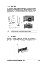
... slots support PCI cards such as LAN card, SCSI card, USB card, and other cards that supports +1.5V AGP 8X cards. ASUS A7N8X-VM/400 motherboard user guide 1-13 This figure shows a typical PCI card installed into a slot. Note the notches on the card golden fingers to ensure that they fit... the AGP slot on the motherboard. The AGP slot also supports Digital Video Output (DVO) interface cards (AGP-NV-DVI) for digital display on new-generation LCD monitors and projectors.
... slots support PCI cards such as LAN card, SCSI card, USB card, and other cards that supports +1.5V AGP 8X cards. ASUS A7N8X-VM/400 motherboard user guide 1-13 This figure shows a typical PCI card installed into a slot. Note the notches on the card golden fingers to ensure that they fit... the AGP slot on the motherboard. The AGP slot also supports Digital Video Output (DVO) interface cards (AGP-NV-DVI) for digital display on new-generation LCD monitors and projectors.

Motherboard DIY Troubleshooting Guide
Page 24
...internal USB header that you can connect to front USB ports. • This feature requires a power supply that can provide at least 2A on the motherboard. 1. USBPW34 and USBPW56 are set to +5VSB. Set to +5VSB to wake up . • The total current consumed must NOT exceed the... are set to pins 1-2 (+5V) by default because not all computers have the appropriate power supply to support this feature. USBPW34 12 23 A7N8X-VM A7N8X-VM/400 USB Device Wake Up +5V (Default) +5VSB USBPW12 12 23 +5V (Default) +5VSB USBPW56 12 23 +5V (Default) +5VSB 1-14 Chapter 1: ...
...internal USB header that you can connect to front USB ports. • This feature requires a power supply that can provide at least 2A on the motherboard. 1. USBPW34 and USBPW56 are set to +5VSB. Set to +5VSB to wake up . • The total current consumed must NOT exceed the... are set to pins 1-2 (+5V) by default because not all computers have the appropriate power supply to support this feature. USBPW34 12 23 A7N8X-VM A7N8X-VM/400 USB Device Wake Up +5V (Default) +5VSB USBPW12 12 23 +5V (Default) +5VSB USBPW56 12 23 +5V (Default) +5VSB 1-14 Chapter 1: ...

Motherboard DIY Troubleshooting Guide
Page 25
... is powered by the onboard button battery cell. Replace the jumper cap to re-enter data. Re-install the battery. 5. A7N8X-VM CLRTC1 12 23 Normal A7N8X-VM/400 Clear RTC RAM (Default) Clear CMOS ASUS A7N8X-VM/400 motherboard user guide 1-15 2. Hold down the key during the boot process and enter BIOS setup to the original position, [1-2]. 4. Remove...
... is powered by the onboard button battery cell. Replace the jumper cap to re-enter data. Re-install the battery. 5. A7N8X-VM CLRTC1 12 23 Normal A7N8X-VM/400 Clear RTC RAM (Default) Clear CMOS ASUS A7N8X-VM/400 motherboard user guide 1-15 2. Hold down the key during the boot process and enter BIOS setup to the original position, [1-2]. 4. Remove...

Motherboard DIY Troubleshooting Guide
Page 26
... cables. • For UltraDMA133 IDE devices, use a 40-pin 80-conductor cable. SEC_IDE PRI_IDE A7N8X-VM/400 IDE Connectors PIN 1 2. A7N8X-VM NOTE: Orient the red markings (usually zigzag) on the UltraDMA cable connector. After connecting one end to the motherboard, connect the other end to the floppy drive. (Pin 5 is removed to match the covered...
... cables. • For UltraDMA133 IDE devices, use a 40-pin 80-conductor cable. SEC_IDE PRI_IDE A7N8X-VM/400 IDE Connectors PIN 1 2. A7N8X-VM NOTE: Orient the red markings (usually zigzag) on the UltraDMA cable connector. After connecting one end to the motherboard, connect the other end to the floppy drive. (Pin 5 is removed to match the covered...

Motherboard DIY Troubleshooting Guide
Page 27
3. ASUS A7N8X-VM/400 motherboard user guide 1-17 The minimum recommended wattage is purchased separately. ATX power connectors (20-pin ATXPWR1) These connectors connect to an open slot in the chassis. Connect one orientation. USB+5V USB_P6USB_P6+ GND NC A7N8X-VM USB+5V USB_P5USB_P5+ GND A7N8X-VM/400 USB 2.0 Header...(10-1 pin USB56) If the USB ports on the +5-volt standby lead (+5VSB). ATXPWR1 A7N8X-VM +12.0VDC +5VSB PWR_OK COM +5.0VDC COM +5.0VDC COM +3.3VDC +3.3VDC A7N8X-VM/400 ATX Power Connector +5.0VDC +5.0VDC -5.0VDC COM COM COM PS_ON# COM -12.0VDC +3.3VDC ...
3. ASUS A7N8X-VM/400 motherboard user guide 1-17 The minimum recommended wattage is purchased separately. ATX power connectors (20-pin ATXPWR1) These connectors connect to an open slot in the chassis. Connect one orientation. USB+5V USB_P6USB_P6+ GND NC A7N8X-VM USB+5V USB_P5USB_P5+ GND A7N8X-VM/400 USB 2.0 Header...(10-1 pin USB56) If the USB ports on the +5-volt standby lead (+5VSB). ATXPWR1 A7N8X-VM +12.0VDC +5VSB PWR_OK COM +5.0VDC COM +5.0VDC COM +3.3VDC +3.3VDC A7N8X-VM/400 ATX Power Connector +5.0VDC +5.0VDC -5.0VDC COM COM COM PS_ON# COM -12.0VDC +3.3VDC ...

Motherboard DIY Troubleshooting Guide
Page 28
...MIDI devices for playing or editing audio files. +5V J1B2 J1CY GND GND J1CX J1B1 +5V MIDI_IN J2B2 J2CY MIDI_OUT J2CX J2B1 +5V A7N8X-VM A7N8X-VM/400 Game Connector GAME1 The USB/GAME port module is purchased separately. 6. Connect the fan cable plugs to the fan connectors on the fan ... connector supports a GAME/MIDI port module. Do not place jumper caps on the motherboard, making sure that the black wire of each cable matches CPU_FAN1 Rotation +12V GND A7N8X-VM CHA_FAN GND +12V Rotation A7N8X-VM/400 Fan Connectors Do not forget to connect the fan cables to an open slot in...
...MIDI devices for playing or editing audio files. +5V J1B2 J1CY GND GND J1CX J1B1 +5V MIDI_IN J2B2 J2CY MIDI_OUT J2CX J2B1 +5V A7N8X-VM A7N8X-VM/400 Game Connector GAME1 The USB/GAME port module is purchased separately. 6. Connect the fan cable plugs to the fan connectors on the fan ... connector supports a GAME/MIDI port module. Do not place jumper caps on the motherboard, making sure that the black wire of each cable matches CPU_FAN1 Rotation +12V GND A7N8X-VM CHA_FAN GND +12V Rotation A7N8X-VM/400 Fan Connectors Do not forget to connect the fan cables to an open slot in...

Motherboard DIY Troubleshooting Guide
Page 29
When you wish to record a chassis intrusion event. 7. A7N8X-VM CHASSIS1 +5VSB_MB Chassis Signal GND A7N8X-VM/400 Chassis Alarm Lead (Default) 8. Front panel audio connectors (10-1 pin FP_AUDIO) This connects the front panel audio module that allows convenient connection and control of .... The connector requires an external detection mechanism such as a chassis intrusion sensor or microswitch. AGND +5VA BLINE_OUT_R BLINE_OUT_L MIC2 MICPWR Line out_R NC Line out_L A7N8X-VM FP_AUDIO A7N8X-VM/400 Front Panel Audio Connector ASUS A7N8X-VM/400 motherboard user guide 1-19
When you wish to record a chassis intrusion event. 7. A7N8X-VM CHASSIS1 +5VSB_MB Chassis Signal GND A7N8X-VM/400 Chassis Alarm Lead (Default) 8. Front panel audio connectors (10-1 pin FP_AUDIO) This connects the front panel audio module that allows convenient connection and control of .... The connector requires an external detection mechanism such as a chassis intrusion sensor or microswitch. AGND +5VA BLINE_OUT_R BLINE_OUT_L MIC2 MICPWR Line out_R NC Line out_L A7N8X-VM FP_AUDIO A7N8X-VM/400 Front Panel Audio Connector ASUS A7N8X-VM/400 motherboard user guide 1-19

Motherboard DIY Troubleshooting Guide
Page 31
... pin SPDIF1) This connector is for S/PDIF IN, the LINE_OUT outputs the sound. SPDIF_OUT +5V SPDIF_IN GND GND A7N8X-VM SPDIF1 1 A7N8X-VM/400 Digital Audio Connector When you input sound for an optional S/PDIF audio module that allows digital instead of the system chassis...separately. Mute LINE_OUT to this connector, then install the module into a slot opening at the back of analog sound input and output. ASUS A7N8X-VM/400 motherboard user guide 1-21 The S/PDIF port module is purchased separately. Serial connector (10-1 pin COM2) This connector accommodates a second serial...
... pin SPDIF1) This connector is for S/PDIF IN, the LINE_OUT outputs the sound. SPDIF_OUT +5V SPDIF_IN GND GND A7N8X-VM SPDIF1 1 A7N8X-VM/400 Digital Audio Connector When you input sound for an optional S/PDIF audio module that allows digital instead of the system chassis...separately. Mute LINE_OUT to this connector, then install the module into a slot opening at the back of analog sound input and output. ASUS A7N8X-VM/400 motherboard user guide 1-21 The S/PDIF port module is purchased separately. Serial connector (10-1 pin COM2) This connector accommodates a second serial...
Motherboard DIY Troubleshooting Guide
Page 35
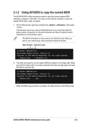
... on the screen is complete, the utility returns to store the file. Reading flash ..... done A:\> When the BIOS copy process is for the extension name. ASUS A7N8X-VM/400 motherboard user guide 2-3 At the DOS prompt, type the command line: afudos /o, then press . The utility will copy the current system BIOS by default to the...
... on the screen is complete, the utility returns to store the file. Reading flash ..... done A:\> When the BIOS copy process is for the extension name. ASUS A7N8X-VM/400 motherboard user guide 2-3 At the DOS prompt, type the command line: afudos /o, then press . The utility will copy the current system BIOS by default to the...
Motherboard DIY Troubleshooting Guide
Page 37
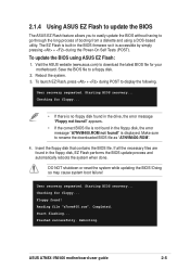
...as "A7NVM400.ROM". 4. User recovery requested. Insert the floppy disk that contains the BIOS file. Start flashing... Visit the ASUS website (www.asus.com) to download the latest BIOS file for floppy... To launch EZ Flash, press + during the Power-On Self Tests... Using ASUS EZ Flash to update the BIOS The ASUS EZ Flash feature allows you to easily update the BIOS without having to go through the long process of booting from a diskette and using ASUS EZ Flash: 1. Checking for your motherboard. Reading file "a7nvm400.rom". Rebooting. ASUS A7N8X-VM/400 motherboard user guide...
...as "A7NVM400.ROM". 4. User recovery requested. Insert the floppy disk that contains the BIOS file. Start flashing... Visit the ASUS website (www.asus.com) to download the latest BIOS file for floppy... To launch EZ Flash, press + during the Power-On Self Tests... Using ASUS EZ Flash to update the BIOS The ASUS EZ Flash feature allows you to easily update the BIOS without having to go through the long process of booting from a diskette and using ASUS EZ Flash: 1. Checking for your motherboard. Reading file "a7nvm400.rom". Rebooting. ASUS A7N8X-VM/400 motherboard user guide...

Motherboard DIY Troubleshooting Guide
Page 39
Click Next. 5. Select the file, click Save, then follow the screen instructions to complete the update process. From the FTP site, select the BIOS version that you to download. 4. Follow the instructions on the succeeding screens to complete the update process. ASUS A7N8X-VM/400 motherboard user guide 2-7 If you selected the option to update the BIOS from a file, a window pops up prompting you wish to locate the file.
Click Next. 5. Select the file, click Save, then follow the screen instructions to complete the update process. From the FTP site, select the BIOS version that you to download. 4. Follow the instructions on the succeeding screens to complete the update process. ASUS A7N8X-VM/400 motherboard user guide 2-7 If you selected the option to update the BIOS from a file, a window pops up prompting you wish to locate the file.


