
User Guide
Page 3
Contents Safety information...iv About this guide...iv Package contents...vi A58M-K specifications summary vi Product introduction 1.1 Before you proceed 1-1 1.2 Motherboard overview 1-2 1.3 Accelerated Processing Unit (APU 1-4 1.4 System memory 1-7 1.5 Expansion slots 1-10 1.6 Jumpers...1-12 1.7 Connectors 1-13 1.8 Onboard LEDs 1-... 2-9 2.4 Main menu...2-10 2.5 Ai Tweaker menu 2-11 2.6 Advanced menu 2-12 2.7 Monitor menu 2-12 2.8 Boot menu...2-13 2.9 Tools menu 2-14 2.10 Exit menu...2-14 Appendices Notices...A-1 ASUS contact information A-4 iii
Contents Safety information...iv About this guide...iv Package contents...vi A58M-K specifications summary vi Product introduction 1.1 Before you proceed 1-1 1.2 Motherboard overview 1-2 1.3 Accelerated Processing Unit (APU 1-4 1.4 System memory 1-7 1.5 Expansion slots 1-10 1.6 Jumpers...1-12 1.7 Connectors 1-13 1.8 Onboard LEDs 1-... 2-9 2.4 Main menu...2-10 2.5 Ai Tweaker menu 2-11 2.6 Advanced menu 2-12 2.7 Monitor menu 2-12 2.8 Boot menu...2-13 2.9 Tools menu 2-14 2.10 Exit menu...2-14 Appendices Notices...A-1 ASUS contact information A-4 iii
User Guide
Page 6
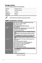
.../dual-graphics/Pages/ dual-graphics.aspx#3 for the AMD® APU support list. resolution 2560x1600@60Hz Supports VGA with max. A58M-K specifications summary APU Chipset Memory Graphics Expansion slots AMD® FM2+ Socket for AMD® A-series/Athlon™ Series processors... your motherboard package for the following items. Motherboard Cables Accessories Application DVD Documentation ASUS A58M-K motherboard 2 x Serial ATA 3.0 Gb/s cables 1 x I/O Shield Support DVD User Guide If any of the above DIMMs. ASUS will update the memory QVL once the DIMMs are using a Windows® ...
.../dual-graphics/Pages/ dual-graphics.aspx#3 for the AMD® APU support list. resolution 2560x1600@60Hz Supports VGA with max. A58M-K specifications summary APU Chipset Memory Graphics Expansion slots AMD® FM2+ Socket for AMD® A-series/Athlon™ Series processors... your motherboard package for the following items. Motherboard Cables Accessories Application DVD Documentation ASUS A58M-K motherboard 2 x Serial ATA 3.0 Gb/s cables 1 x I/O Shield Support DVD User Guide If any of the above DIMMs. ASUS will update the memory QVL once the DIMMs are using a Windows® ...
User Guide
Page 7
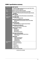
... (purple) 1 x DVI-D port 1 x VGA output port 1 x LAN (RJ-45) port 4 x USB 2.0/1.1 ports 8-channel audio I /O - 3x More durable corrosion-resistant coating ASUS Exclusive Features - A58M-K specifications summary Storage / RAID LAN Audio USB ASUS unique features Back Panel I/O ports AMD® A58 FCH - 4 x Serial ATA 3.0Gb/s connectors (dark brown) support RAID 0, RAID 1, RAID 10, and...
... (purple) 1 x DVI-D port 1 x VGA output port 1 x LAN (RJ-45) port 4 x USB 2.0/1.1 ports 8-channel audio I /O - 3x More durable corrosion-resistant coating ASUS Exclusive Features - A58M-K specifications summary Storage / RAID LAN Audio USB ASUS unique features Back Panel I/O ports AMD® A58 FCH - 4 x Serial ATA 3.0Gb/s connectors (dark brown) support RAID 0, RAID 1, RAID 10, and...

User Guide
Page 9
... as the power supply case, to avoid damaging them due to static electricity. • Hold components by the edges to the motherboard, peripherals, or components. ASUS A58M-K 1-1
... as the power supply case, to avoid damaging them due to static electricity. • Hold components by the edges to the motherboard, peripherals, or components. ASUS A58M-K 1-1

User Guide
Page 11
...240-pin module) DDR3 DIMM_B1 (64bit, 240-pin module) SOCKET FM2+ DVI_VGA 22.6cm(8.9in) USB1112 EATXPWR LAN_USB12 1 AUDIO 8111 GR A58M-K PCIEX16 Super I/O SB_PWR PCIEX1_1 BATTERY AMD® 5 A58 SPEAKER SATA3G_4 ALC 887 PCI1 F_PANEL 6 SPDIF_OUT 64Mb BIOS 7 TPM USB56 ...COM) 13. Front panel audio connector (10-1 pin AAFP) Page 1-15 1-4 1-14 1-7 1-17 1-16 1-17 1-19 1-12 1-18 1-15 1-16 1-19 1-18 ASUS A58M-K 1-3 ATX power connectors (24-pin EATXPWR, 4-pin ATX12V) 2. Speaker connector (4-pin SPEAKER) 6. AMD FM2+ socket 3. USB 2.0 connectors (10-1 pin USB34, USB56) ...
...240-pin module) DDR3 DIMM_B1 (64bit, 240-pin module) SOCKET FM2+ DVI_VGA 22.6cm(8.9in) USB1112 EATXPWR LAN_USB12 1 AUDIO 8111 GR A58M-K PCIEX16 Super I/O SB_PWR PCIEX1_1 BATTERY AMD® 5 A58 SPEAKER SATA3G_4 ALC 887 PCI1 F_PANEL 6 SPDIF_OUT 64Mb BIOS 7 TPM USB56 ...COM) 13. Front panel audio connector (10-1 pin AAFP) Page 1-15 1-4 1-14 1-7 1-17 1-16 1-17 1-19 1-12 1-18 1-15 1-16 1-19 1-18 ASUS A58M-K 1-3 ATX power connectors (24-pin EATXPWR, 4-pin ATX12V) 2. Speaker connector (4-pin SPEAKER) 6. AMD FM2+ socket 3. USB 2.0 connectors (10-1 pin USB34, USB56) ...

User Guide
Page 13
3 4 1.3.2 APU heatsink and fan assembly installation Apply the Thermal Interface Material to the APU heatsink and APU before you install the heatsink and fan if necessary. To install the APU heatsink and fan assembly 1 2 ASUS A58M-K 1-5
3 4 1.3.2 APU heatsink and fan assembly installation Apply the Thermal Interface Material to the APU heatsink and APU before you install the heatsink and fan if necessary. To install the APU heatsink and fan assembly 1 2 ASUS A58M-K 1-5

User Guide
Page 15
The figure illustrates the location of the DDR3 DIMM sockets: DIMM_A1 DIMM_B1 A58M-K A58M-K 240-pin DDR3 DIMM sockets Channel Channel A Channel B Sockets DIMM_A1 DIMM_B1 ASUS A58M-K 1-7 1.4 System memory 1.4.1 Overview The motherboard comes with less power consumption. DDR3 modules are developed for better performance with two Double Data Rate 3 (DDR3) Dual Inline Memory Modules (DIMM) sockets. A DDR3 module has the same physical dimensions as a DDR2 DIMM but is notched differently to prevent installation on a DDR2 DIMM socket.
The figure illustrates the location of the DDR3 DIMM sockets: DIMM_A1 DIMM_B1 A58M-K A58M-K 240-pin DDR3 DIMM sockets Channel Channel A Channel B Sockets DIMM_A1 DIMM_B1 ASUS A58M-K 1-7 1.4 System memory 1.4.1 Overview The motherboard comes with less power consumption. DDR3 modules are developed for better performance with two Double Data Rate 3 (DDR3) Dual Inline Memory Modules (DIMM) sockets. A DDR3 module has the same physical dimensions as a DDR2 DIMM but is notched differently to prevent installation on a DDR2 DIMM socket.

User Guide
Page 17
1.4.3 1 Installing a DIMM 2 3 To remove a DIMM B A ASUS A58M-K 1-9
1.4.3 1 Installing a DIMM 2 3 To remove a DIMM B A ASUS A58M-K 1-9

User Guide
Page 19
... graphics cards that comply with the PCI Express specifications. On Chip USB OHCI 1/2/3/4 - - PCIEx1_1 shared - - - - - - - PCI1 slot - - - - shared - - - - - shared - - - - - - shared - - - - - shared - - - - shared - - - - - Realtek LAN controller - - ASUS A58M-K 1-11 shared - - - IRQ assignments for this motherboard A B C D E F G H PCIEx16_1 - - HD audio shared - - - - - - - SATA controller - - - On Chip USB EHCI 1/2/3 -
... graphics cards that comply with the PCI Express specifications. On Chip USB OHCI 1/2/3/4 - - PCIEx1_1 shared - - - - - - - PCI1 slot - - - - shared - - - - - shared - - - - - - shared - - - - - shared - - - - shared - - - - - Realtek LAN controller - - ASUS A58M-K 1-11 shared - - - IRQ assignments for this motherboard A B C D E F G H PCIEx16_1 - - HD audio shared - - - - - - - SATA controller - - - On Chip USB EHCI 1/2/3 -

User Guide
Page 21
... Status Description OFF 10Mbps connection ORANGE 100Mbps connection GREEN 1Gbps connection LAN port 4. Line In port (light blue). Line Out port (lime). Microphone port (pink). ASUS A58M-K 1-13 Video Graphics Adapter (VGA) port. LAN port LED indications ACT/LINK SPEED LED LED Activity/Link LED Status Off Orange Orange (Blinking) Orange (Blinking...
... Status Description OFF 10Mbps connection ORANGE 100Mbps connection GREEN 1Gbps connection LAN port 4. Line In port (light blue). Line Out port (lime). Microphone port (pink). ASUS A58M-K 1-13 Video Graphics Adapter (VGA) port. LAN port LED indications ACT/LINK SPEED LED LED Activity/Link LED Status Off Orange Orange (Blinking) Orange (Blinking...

User Guide
Page 23
... power connectors (24-pin EATXPWR, 4-pin ATX12V) These connectors are for an additional Sony/Philips Digital Interface (S/PDIF) port. +5V SPDIFOUT GND A58M-K SPDIF_OUT A58M-K Digital audio connector The S/PDIF module is inadequate. • If you use an ATX 12V Specification 2.0‑compliant power supply unit (PSU) ...push down firmly until the connectors completely fit. The system may become unstable or may not boot up if the power is purchased separately. ASUS A58M-K 1-15 2. This PSU type has 24-pin and 4-pin power plugs. • If you intend to install additional devices. The ...
... power connectors (24-pin EATXPWR, 4-pin ATX12V) These connectors are for an additional Sony/Philips Digital Interface (S/PDIF) port. +5V SPDIFOUT GND A58M-K SPDIF_OUT A58M-K Digital audio connector The S/PDIF module is inadequate. • If you use an ATX 12V Specification 2.0‑compliant power supply unit (PSU) ...push down firmly until the connectors completely fit. The system may become unstable or may not boot up if the power is purchased separately. ASUS A58M-K 1-15 2. This PSU type has 24-pin and 4-pin power plugs. • If you intend to install additional devices. The ...

User Guide
Page 25
... This 2-pin connector is for the chassis-mounted system warning speaker. Connect the HDD Activity LED cable to this connector. Ground HWRST# (NC) A58M-K PIN 1 +HDD_LED RESET A58M-K System panel connector • System power LED (2-pin PWR_LED) This 2-pin connector is for system reboot without turning off the system power. ...lights up or flashes when data is read from or written to hear system beeps and warnings. +5V GND GND Speaker Out SPEAKER A58M-K PIN 1 A58M-K Speaker Out Connector ASUS A58M-K 1-17 F_PANEL +PWR LED PWR BTN PWR_LED+ PWR_LEDPWR GND HDD_LED+ HDD_LED-
... This 2-pin connector is for the chassis-mounted system warning speaker. Connect the HDD Activity LED cable to this connector. Ground HWRST# (NC) A58M-K PIN 1 +HDD_LED RESET A58M-K System panel connector • System power LED (2-pin PWR_LED) This 2-pin connector is for system reboot without turning off the system power. ...lights up or flashes when data is read from or written to hear system beeps and warnings. +5V GND GND Speaker Out SPEAKER A58M-K PIN 1 A58M-K Speaker Out Connector ASUS A58M-K 1-17 F_PANEL +PWR LED PWR BTN PWR_LED+ PWR_LEDPWR GND HDD_LED+ HDD_LED-

User Guide
Page 27
...ON, in sleep mode, or in any of these connectors, then install the module to 480Mbps connection speed. SB_PWR A58M-K ON OFF Standby Power Powered Off A58M-K Onboard LED ASUS A58M-K 1-19 Doing so will damage the motherboard! USB 2.0 connectors (10-1 pin USB34, USB56) These connectors are.... 1.8 Onboard LEDs 1. USB56 USB34 USB+5V USB_P5USB_P5+ GND NC USB+5V USB_P3USB_P3+ GND NC A58M-K PIN 1 PIN 1 USB+5V USB_P6USB_P6+ GND USB+5V USB_P4USB_P4+ GND A58M-K USB2.0 connectors Never connect a 1394 cable to any motherboard component. The illustration below shows the ...
...ON, in sleep mode, or in any of these connectors, then install the module to 480Mbps connection speed. SB_PWR A58M-K ON OFF Standby Power Powered Off A58M-K Onboard LED ASUS A58M-K 1-19 Doing so will damage the motherboard! USB 2.0 connectors (10-1 pin USB34, USB56) These connectors are.... 1.8 Onboard LEDs 1. USB56 USB34 USB+5V USB_P5USB_P5+ GND NC USB+5V USB_P3USB_P3+ GND NC A58M-K PIN 1 PIN 1 USB+5V USB_P6USB_P6+ GND USB+5V USB_P4USB_P4+ GND A58M-K USB2.0 connectors Never connect a 1394 cable to any motherboard component. The illustration below shows the ...
User Guide
Page 29
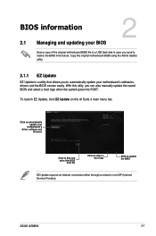
To launch EZ Update, click EZ Update on the AI Suite 3 main menu bar. ASUS A58M-K 2-1 With this utlity, you need to restore the BIOS in case you can also manually update the saved BIOS and select a boot logo when the ... update the BIOS EZ Update requires an Internet connection either through a network or an ISP (Internet Service Provider). Copy the original motherboard BIOS using the ASUS Update utility. 2.1.1 EZ Update EZ Update is a utility that allows you to automatically update your motherboard's driver, software and firmware Click to find and select...
To launch EZ Update, click EZ Update on the AI Suite 3 main menu bar. ASUS A58M-K 2-1 With this utlity, you need to restore the BIOS in case you can also manually update the saved BIOS and select a boot logo when the ... update the BIOS EZ Update requires an Internet connection either through a network or an ISP (Internet Service Provider). Copy the original motherboard BIOS using the ASUS Update utility. 2.1.1 EZ Update EZ Update is a utility that allows you to automatically update your motherboard's driver, software and firmware Click to find and select...
User Guide
Page 31
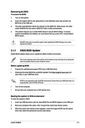
... or the USB flash drive that you to enter BIOS Setup to load default BIOS values. Doing so can cause system boot failure! 2.1.4 ASUS BIOS Updater ASUS BIOS Updater allows you to launch the select boot device screen. 3. NTFS is in single partition and in FAT32/16 format. • ...is not supported under FreeDOS environment. Ensure that your computer then press to update the BIOS in DOS: 1. Turn on your USB flash drive. ASUS A58M-K 2-3 The utility automatically checks the devices for reference only and may not be exactly the same as the boot device. DO NOT shut down ...
... or the USB flash drive that you to enter BIOS Setup to load default BIOS values. Doing so can cause system boot failure! 2.1.4 ASUS BIOS Updater ASUS BIOS Updater allows you to launch the select boot device screen. 3. NTFS is in single partition and in FAT32/16 format. • ...is not supported under FreeDOS environment. Ensure that your computer then press to update the BIOS in DOS: 1. Turn on your USB flash drive. ASUS A58M-K 2-3 The utility automatically checks the devices for reference only and may not be exactly the same as the boot device. DO NOT shut down ...
User Guide
Page 33
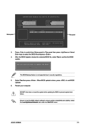
... to load the BIOS default settings to update the BIOS? Drives panel ASUSTeK BIOS Updater for DOS V1.30 [2014/01/01] Current ROM BOARD: A58M-K VER: 0210 (H :00 B :00) DATE: 02/12/2014 PATH: C:\ Update ROM BOARD: Unknown VER: Unknown DATE: Unknown C: FORMAN~1 D: A58MK .CAP 8390626...keys to prevent system boot failure. Select Yes then press . Select the Load Optimized Defaults item under the Exit BIOS menu. Restart your computer. ASUS A58M-K 2-5 DO NOT shut down or reset the system while updating the BIOS to select the BIOS file and press . 4. After the BIOS ...
... to load the BIOS default settings to update the BIOS? Drives panel ASUSTeK BIOS Updater for DOS V1.30 [2014/01/01] Current ROM BOARD: A58M-K VER: 0210 (H :00 B :00) DATE: 02/12/2014 PATH: C:\ Update ROM BOARD: Unknown VER: Unknown DATE: Unknown C: FORMAN~1 D: A58MK .CAP 8390626...keys to prevent system boot failure. Select Yes then press . Select the Load Optimized Defaults item under the Exit BIOS menu. Restart your computer. ASUS A58M-K 2-5 DO NOT shut down or reset the system while updating the BIOS to select the BIOS file and press . 4. After the BIOS ...

User Guide
Page 35
... mode functions Normal mode Power Saving mode Loads optimized default Displays the system properties of the basic system information, and allows you to the system. ASUS A58M-K 2-7 EZ Mode By default, the EZ Mode screen appears when you installed to the system. • The Boot Menu(F8) button is available only when...
... mode functions Normal mode Power Saving mode Loads optimized default Displays the system properties of the basic system information, and allows you to the system. ASUS A58M-K 2-7 EZ Mode By default, the EZ Mode screen appears when you installed to the system. • The Boot Menu(F8) button is available only when...

User Guide
Page 37
... submenu options • User-configurable items such as language and boot device order • Configuration items such as Memory SPD Information, system time and date ASUS A58M-K 2-9
... submenu options • User-configurable items such as language and boot device order • Configuration items such as Memory SPD Information, system time and date ASUS A58M-K 2-9

User Guide
Page 39
2.5 Ai Tweaker menu The Ai Tweaker menu items allow you installed on the CPU and DIMM model you to configure overclocking-related items. Be cautious when changing the settings of the Ai Tweaker menu items. Incorrect field values can cause the system to display the other items. ASUS A58M-K 2-11 The configuration options for this section vary depending on the motherboard. Scroll down to malfunction.
2.5 Ai Tweaker menu The Ai Tweaker menu items allow you installed on the CPU and DIMM model you to configure overclocking-related items. Be cautious when changing the settings of the Ai Tweaker menu items. Incorrect field values can cause the system to display the other items. ASUS A58M-K 2-11 The configuration options for this section vary depending on the motherboard. Scroll down to malfunction.

User Guide
Page 41
Scroll down to change the system boot options. 2.8 Boot menu The Boot menu items allow you to display the other items. ASUS A58M-K 2-13
Scroll down to change the system boot options. 2.8 Boot menu The Boot menu items allow you to display the other items. ASUS A58M-K 2-13


