
User Guide
Page 2
... from http://support.asus.com/download or (2) for free by downloading it , may not be distributed WITHOUT ANY WARRANTY and licensed under the same license as required under the Lesser General Public License Version ("LGPL") and/or other additional data, you . No part of this information. or (2) the serial number of this manual, including the products and software described in...
... from http://support.asus.com/download or (2) for free by downloading it , may not be distributed WITHOUT ANY WARRANTY and licensed under the same license as required under the Lesser General Public License Version ("LGPL") and/or other additional data, you . No part of this information. or (2) the serial number of this manual, including the products and software described in...
User Guide
Page 4
... before using , contact your local power company. • If the power supply is set to fix it by yourself. Safety information Electrical safety • To prevent electrical shock hazard, disconnect the power cable from the electrical outlet before relocating the system. • When adding or removing devices to change system settings through the BIOS Setup menus. If you need when installing and configuring the motherboard. Detailed...
... before using , contact your local power company. • If the power supply is set to fix it by yourself. Safety information Electrical safety • To prevent electrical shock hazard, disconnect the power cable from the electrical outlet before relocating the system. • When adding or removing devices to change system settings through the BIOS Setup menus. If you need when installing and configuring the motherboard. Detailed...
User Guide
Page 6
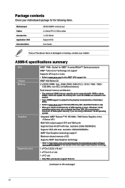
... for the following items. Motherboard Cables Accessories Application DVD Documentation ASUS A58M-K motherboard 2 x Serial ATA 3.0 Gb/s cables 1 x I/O Shield Support DVD User Guide If any of the above DIMMs. ASUS will update the memory QVL once the DIMMs are using a Windows® 32-bit operating system. resolution 2560x1600@60Hz Supports VGA with max. resolution 1920x1600@60Hz AMD® Dual Graphics technology support* Maximum shared memory of 4GB capacity or more, Windows® 32-bit operating system may only recognize less...
... for the following items. Motherboard Cables Accessories Application DVD Documentation ASUS A58M-K motherboard 2 x Serial ATA 3.0 Gb/s cables 1 x I/O Shield Support DVD User Guide If any of the above DIMMs. ASUS will update the memory QVL once the DIMMs are using a Windows® 32-bit operating system. resolution 2560x1600@60Hz Supports VGA with max. resolution 1920x1600@60Hz AMD® Dual Graphics technology support* Maximum shared memory of 4GB capacity or more, Windows® 32-bit operating system may only recognize less...
User Guide
Page 7
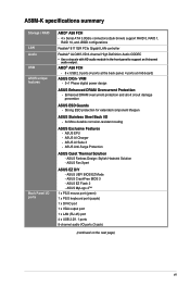
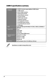
...- 8 x USB 2.0 ports (4 ports at the back panel, 4 ports at mid-board) ASUS DIGI+ VRM - 3+1 Phase digital power design ASUS Enhanced DRAM Overcurrent Protection - A58M-K specifications summary Storage / RAID LAN Audio USB ASUS unique features Back Panel I/O ports AMD® A58 FCH - 4 x Serial ATA 3.0Gb/s connectors (dark brown) support RAID 0, RAID 1, RAID 10, and JBOD configurations Realtek® 8111GR PCIe Gigabit LAN controller Realtek® ALC887-VD 8-channel High Definition Audio CODEC • Use a chassis with HD audio module in the front panel to support an 8-channel audio output.
...- 8 x USB 2.0 ports (4 ports at the back panel, 4 ports at mid-board) ASUS DIGI+ VRM - 3+1 Phase digital power design ASUS Enhanced DRAM Overcurrent Protection - A58M-K specifications summary Storage / RAID LAN Audio USB ASUS unique features Back Panel I/O ports AMD® A58 FCH - 4 x Serial ATA 3.0Gb/s connectors (dark brown) support RAID 0, RAID 1, RAID 10, and JBOD configurations Realtek® 8111GR PCIe Gigabit LAN controller Realtek® ALC887-VD 8-channel High Definition Audio CODEC • Use a chassis with HD audio module in the front panel to support an 8-channel audio output.
User Guide
Page 8
... summary Internal I/O connectors BIOS Support DVD Operating System Support Form factor 2 x USB 2.0 connectors support additional 4 USB 2.0 ports 1 x COM connector 4 x SATA 3.0Gb/s connectors 1 x System panel connector 1 x Internal Speaker connector 1 x CPU fan connector 1 x S/PDIF output connector 1 x Chassis fan connector 1 x Front panel audio connector 1 x 24-pin EATX power connector 1 x 4-pin ATX 12V power connector 1 x TPM header 64 Mb Flash ROM, UEFI AMI BIOS, PnP, DMI 2.0, WfM 2.0, SM BIOS 2.7, ACPI 2.0a Drivers ASUS Update ASUS utilities Anti-Virus software (OEM version) Windows®...
... summary Internal I/O connectors BIOS Support DVD Operating System Support Form factor 2 x USB 2.0 connectors support additional 4 USB 2.0 ports 1 x COM connector 4 x SATA 3.0Gb/s connectors 1 x System panel connector 1 x Internal Speaker connector 1 x CPU fan connector 1 x S/PDIF output connector 1 x Chassis fan connector 1 x Front panel audio connector 1 x 24-pin EATX power connector 1 x 4-pin ATX 12V power connector 1 x TPM header 64 Mb Flash ROM, UEFI AMI BIOS, PnP, DMI 2.0, WfM 2.0, SM BIOS 2.7, ACPI 2.0a Drivers ASUS Update ASUS utilities Anti-Virus software (OEM version) Windows®...

User Guide
Page 11
ATX power connectors (24-pin EATXPWR, 4-pin ATX12V) 2. AMD FM2+ socket 3. Speaker connector (4-pin SPEAKER) 6. Clear RTC RAM (3-pin CLRTC) 10. Standby power LED (SB_PWR) 14. Serial port connector (10-1 pin COM) 13. Front panel audio connector (10-1 pin AAFP) Page 1-15 1-4 1-14 1-7 1-17 1-16 1-17 1-19 1-12 1-18 1-15 1-16 1-19 1-18 ASUS A58M-K 1-3 DDR3 DIMM slots 5. USB 2.0 connectors (10-1 pin USB34, USB56) 9. Digital audio connector (4-1 pin SPDIF_OUT) 12. System panel connector (10-1 pin F_PANEL) 8. 1.2.3 Motherboard layout 1 2 3 4 18.3cm(7.2in) KBMS ATX12V DIGI +...
ATX power connectors (24-pin EATXPWR, 4-pin ATX12V) 2. AMD FM2+ socket 3. Speaker connector (4-pin SPEAKER) 6. Clear RTC RAM (3-pin CLRTC) 10. Standby power LED (SB_PWR) 14. Serial port connector (10-1 pin COM) 13. Front panel audio connector (10-1 pin AAFP) Page 1-15 1-4 1-14 1-7 1-17 1-16 1-17 1-19 1-12 1-18 1-15 1-16 1-19 1-18 ASUS A58M-K 1-3 DDR3 DIMM slots 5. USB 2.0 connectors (10-1 pin USB34, USB56) 9. Digital audio connector (4-1 pin SPDIF_OUT) 12. System panel connector (10-1 pin F_PANEL) 8. 1.2.3 Motherboard layout 1 2 3 4 18.3cm(7.2in) KBMS ATX12V DIGI +...

User Guide
Page 16
... 32-bit Windows® OS, when you are available in the market. • The default memory operation frequency is dependent on the motherboard, the actual usable memory for overclocking may install varying memory sizes in Channel A and Channel B. Install a maximum of 3GB system memory if you install 4GB or more efficient memory cooling system to support a full memory load (2 DIMMs) or overclocking condition. • Refer to www.asus.com for the dual-channel configuration. To...
... 32-bit Windows® OS, when you are available in the market. • The default memory operation frequency is dependent on the motherboard, the actual usable memory for overclocking may install varying memory sizes in Channel A and Channel B. Install a maximum of 3GB system memory if you install 4GB or more efficient memory cooling system to support a full memory load (2 DIMMs) or overclocking condition. • Refer to www.asus.com for the dual-channel configuration. To...
User Guide
Page 18
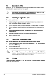
... the slot. 5. Unplug the power cord before adding or removing expansion cards. Install the software drivers for the card. 2. Before installing the expansion card, read the documentation that came with PCI specifications. 1-10 Chapter 1: Product introduction Remove the system unit cover (if your motherboard is completely seated on BIOS setup. 2. Align the card connector with the screw you intend to the card. 3. When using PCI cards on the system and change the necessary BIOS settings...
... the slot. 5. Unplug the power cord before adding or removing expansion cards. Install the software drivers for the card. 2. Before installing the expansion card, read the documentation that came with PCI specifications. 1-10 Chapter 1: Product introduction Remove the system unit cover (if your motherboard is completely seated on BIOS setup. 2. Align the card connector with the screw you intend to the card. 3. When using PCI cards on the system and change the necessary BIOS settings...

User Guide
Page 20
... the key during the boot process and enter BIOS setup to overclocking. A58M-K CLRTC 12 23 Normal (Default) A58M-K Clear RTC RAM To erase the RTC RAM: Clear RTC 1. You can clear the CMOS memory of date, time, and system setup parameters by erasing the CMOS RTC RAM data. The onboard button cell battery powers the RAM data in CMOS. 1.6 Jumpers Clear RTC RAM (3-pin CLRTC) This jumper allows you to overclocking, use the CPU Parameter Recall (C.P.R.) feature. Removing the cap will cause system boot failure...
... the key during the boot process and enter BIOS setup to overclocking. A58M-K CLRTC 12 23 Normal (Default) A58M-K Clear RTC RAM To erase the RTC RAM: Clear RTC 1. You can clear the CMOS memory of date, time, and system setup parameters by erasing the CMOS RTC RAM data. The onboard button cell battery powers the RAM data in CMOS. 1.6 Jumpers Clear RTC RAM (3-pin CLRTC) This jumper allows you to overclocking, use the CPU Parameter Recall (C.P.R.) feature. Removing the cap will cause system boot failure...

User Guide
Page 21
...Area Network (LAN) through a network hub. Line Out port (lime). Microphone port (pink). ASUS A58M-K 1-13 Line In port (light blue). This port connects to the tape, CD, DVD player, or other VGA-compatible devices. 3. In the 4.1, 5.1, and 7.1-channel configurations, the function of the audio ports in 2.1, 4.1, 5.1, or 7.1-channel configuration. LAN (RJ-45) port. This port connects to a headphone or a speaker. This 15-pin port is for a VGA monitor or other audio sources. 5. Video Graphics Adapter (VGA) port. This port connects to the audio configuration table...
...Area Network (LAN) through a network hub. Line Out port (lime). Microphone port (pink). ASUS A58M-K 1-13 Line In port (light blue). This port connects to the tape, CD, DVD player, or other VGA-compatible devices. 3. In the 4.1, 5.1, and 7.1-channel configurations, the function of the audio ports in 2.1, 4.1, 5.1, or 7.1-channel configuration. LAN (RJ-45) port. This port connects to a headphone or a speaker. This 15-pin port is for a VGA monitor or other audio sources. 5. Video Graphics Adapter (VGA) port. This port connects to the audio configuration table...

User Guide
Page 22
... motherboard components. PS/2 Keyboard port (purple). This port is for any DVI-D compatible device. These 4-pin Universal Serial Bus (USB) ports are not jumpers! DVI-D port. DVI-D can't be converted to output RGB Signal to support a 7.1-channel audio output. 7. CPU_FAN CHA_FAN CPU FAN PWM CPU FAN IN CPU FAN PWR GND CHA FAN PWM CHA FAN IN CHA FAN PWR GND A58M-K A58M-K Fan connectors DO NOT forget to connect the fan cables to the fan connectors on the fan connectors. • The CPU_FAN connector supports a CPU fan of the connector...
... motherboard components. PS/2 Keyboard port (purple). This port is for any DVI-D compatible device. These 4-pin Universal Serial Bus (USB) ports are not jumpers! DVI-D port. DVI-D can't be converted to output RGB Signal to support a 7.1-channel audio output. 7. CPU_FAN CHA_FAN CPU FAN PWM CPU FAN IN CPU FAN PWR GND CHA FAN PWM CHA FAN IN CHA FAN PWR GND A58M-K A58M-K Fan connectors DO NOT forget to connect the fan cables to the fan connectors on the fan connectors. • The CPU_FAN connector supports a CPU fan of the connector...

User Guide
Page 24
... installed Serial ATA hard disk drives, you are using Windows® XP SP3 or later version. • When using hot-plug and NCQ, set the type of the system chassis. Connect the serial port module cable to this connector, then install the module to AHCI mode by default. COM PIN 1 RXD DTR DSR CTS DCD TXD GND RTS RI A58M-K A58M-K Serial port connectors The COM module is available only if you can create a RAID 0, RAID 1, or RAID 10 configuration through the onboard controller. A58M...
... installed Serial ATA hard disk drives, you are using Windows® XP SP3 or later version. • When using hot-plug and NCQ, set the type of the system chassis. Connect the serial port module cable to this connector, then install the module to AHCI mode by default. COM PIN 1 RXD DTR DSR CTS DCD TXD GND RTS RI A58M-K A58M-K Serial port connectors The COM module is available only if you can create a RAID 0, RAID 1, or RAID 10 configuration through the onboard controller. A58M...

User Guide
Page 26
... keys, digital certificates, passwords, and data. TPM SB_SUS_STAT GND +3VSB SMBSCL LAD0 +3V LAD3 PCIRST# FRAME PCICLK A58M-K PIN 1 RESET GPIO SERIRQ SMBSDA GND LAD1 LAD2 PWROWN GND A58M-K TPM Connector The TPM module is purchased separately. 9. Front panel audio connector (10-1 pin AAFP) This connector is for a chassis-mounted front panel audio I/O module that you want to connect a high definition front panel audio module to this connector, set the Front Panel Type...
... keys, digital certificates, passwords, and data. TPM SB_SUS_STAT GND +3VSB SMBSCL LAD0 +3V LAD3 PCIRST# FRAME PCICLK A58M-K PIN 1 RESET GPIO SERIRQ SMBSDA GND LAD1 LAD2 PWROWN GND A58M-K TPM Connector The TPM module is purchased separately. 9. Front panel audio connector (10-1 pin AAFP) This connector is for a chassis-mounted front panel audio I/O module that you want to connect a high definition front panel audio module to this connector, set the Front Panel Type...

User Guide
Page 27
... damage the motherboard! The illustration below shows the location of the system chassis. Standby Power LED The motherboard comes with USB 2.0 specification that supports up to 480Mbps connection speed. SB_PWR A58M-K ON OFF Standby Power Powered Off A58M-K Onboard LED ASUS A58M-K 1-19 These USB connectors comply with a standby power LED that lights up to indicate that you should shut down the system and unplug the power cable before removing or plugging in soft-off mode. The USB 2.0 module is...
... damage the motherboard! The illustration below shows the location of the system chassis. Standby Power LED The motherboard comes with USB 2.0 specification that supports up to 480Mbps connection speed. SB_PWR A58M-K ON OFF Standby Power Powered Off A58M-K Onboard LED ASUS A58M-K 1-19 These USB connectors comply with a standby power LED that lights up to indicate that you should shut down the system and unplug the power cable before removing or plugging in soft-off mode. The USB 2.0 module is...
User Guide
Page 28
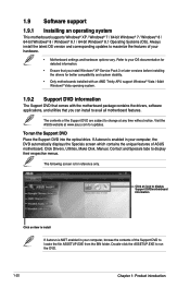
... without notice. 1.9 Software support 1.9.1 Installing an operating system This motherboard supports Windows® XP / Windows® 7 / 64-bit Windows® 7 / Windows® 8 / 64-bit Windows® 8 / Windows® 8.1 / 64-bit Windows® 8.1 Operating Systems (OS). Double-click the ASSETUP.EXE to change at www.asus.com for updates. To run the DVD. 1-20 Chapter 1: Product introduction Refer to your hardware. • Motherboard settings and hardware options vary. Click Drivers, Utilities, Make Disk, Manual, Contact and Specials...
... without notice. 1.9 Software support 1.9.1 Installing an operating system This motherboard supports Windows® XP / Windows® 7 / 64-bit Windows® 7 / Windows® 8 / 64-bit Windows® 8 / Windows® 8.1 / 64-bit Windows® 8.1 Operating Systems (OS). Double-click the ASSETUP.EXE to change at www.asus.com for updates. To run the DVD. 1-20 Chapter 1: Product introduction Refer to your hardware. • Motherboard settings and hardware options vary. Click Drivers, Utilities, Make Disk, Manual, Contact and Specials...
User Guide
Page 29
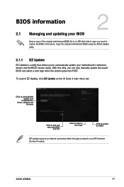
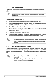
... 3 main menu bar. ASUS A58M-K 2-1 Click to automatically update your BIOS 2 Save a copy of the original motherboard BIOS file to a USB flash disk in case you need to restore the BIOS in the future. BIOS information 2.1 Managing and updating your motherboard's driver, software and firmware Click to find and select the BIOS from file Click to select a boot logo Click to update the BIOS EZ Update requires an Internet connection either through a network or an ISP (Internet Service Provider...
... 3 main menu bar. ASUS A58M-K 2-1 Click to automatically update your BIOS 2 Save a copy of the original motherboard BIOS file to a USB flash disk in case you need to restore the BIOS in the future. BIOS information 2.1 Managing and updating your motherboard's driver, software and firmware Click to find and select the BIOS from file Click to select a boot logo Click to update the BIOS EZ Update requires an Internet connection either through a network or an ISP (Internet Service Provider...
User Guide
Page 30
... BIOS file using the motherboard support DVD or a USB flash drive that contains the latest BIOS file to enable it fails or gets corrupted during the updating process. Press the Up/Down arrow keys to find the USB flash disk that allows you to prevent system boot failure! 2.1.3 ASUS CrashFree BIOS 3 utility The ASUS CrashFree BIOS 3 is an auto recovery tool that contains the latest BIOS, and then press . 5. Insert the USB flash disk that contains the updated BIOS file. • Before using this utility, download...
... BIOS file using the motherboard support DVD or a USB flash drive that contains the latest BIOS file to enable it fails or gets corrupted during the updating process. Press the Up/Down arrow keys to find the USB flash disk that allows you to prevent system boot failure! 2.1.3 ASUS CrashFree BIOS 3 utility The ASUS CrashFree BIOS 3 is an auto recovery tool that contains the latest BIOS, and then press . 5. Insert the USB flash disk that contains the updated BIOS file. • Before using this utility, download...
User Guide
Page 31
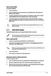
... the USB flash drive that you to enter BIOS Setup to the USB port. 2. The system requires you press to update the BIOS in DOS: 1. Insert the USB flash drive with the latest BIOS file and BIOS Updater to recover BIOS setting. ASUS A58M-K 2-3 Before updating BIOS • Prepare the motherboard support DVD and a USB flash drive. • Download the latest BIOS file and BIOS Updater from http://support.asus.com and save them in this section are for the BIOS file. When the select boot device screen appears, insert the Support DVD...
... the USB flash drive that you to enter BIOS Setup to the USB port. 2. The system requires you press to update the BIOS in DOS: 1. Insert the USB flash drive with the latest BIOS file and BIOS Updater to recover BIOS setting. ASUS A58M-K 2-3 Before updating BIOS • Prepare the motherboard support DVD and a USB flash drive. • Download the latest BIOS file and BIOS Updater from http://support.asus.com and save them in this section are for the BIOS file. When the select boot device screen appears, insert the Support DVD...
User Guide
Page 32
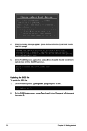
...to switch from Drive C (optical drive) to Drives panel then select D:. 2-4 Chapter 2: Getting started On the FreeDOS prompt, type d: then press to switch the disk from Files panel to Drive D (USB flash drive). Please select boot device: E1: ASUS DVD-E818A6T (4069MB) USB DISK 2.0 (3824MB) UEFI: (FAT) USB DISK 2.0 (3824MB) Enter Setup and to move selection ENTER to select boot device ESC to boot from the DVD/CD. C:/> d: D:/> Updating the BIOS file To update the BIOS file: 1. If no key is detected. D:/> bupdater /pc /g 2. Press ENTER to boot using defaults...
...to switch from Drive C (optical drive) to Drives panel then select D:. 2-4 Chapter 2: Getting started On the FreeDOS prompt, type d: then press to switch the disk from Files panel to Drive D (USB flash drive). Please select boot device: E1: ASUS DVD-E818A6T (4069MB) USB DISK 2.0 (3824MB) UEFI: (FAT) USB DISK 2.0 (3824MB) Enter Setup and to move selection ENTER to select boot device ESC to boot from the DVD/CD. C:/> d: D:/> Updating the BIOS file To update the BIOS file: 1. If no key is detected. D:/> bupdater /pc /g 2. Press ENTER to boot using defaults...

User Guide
Page 34
... To enter BIOS Setup at www.asus.com to download the latest BIOS file for details. • If the system fails to boot after changing any BIOS setting, try to clear the CMOS and reset the motherboard to guide you in this motherboard. • Ensure that a USB mouse is connected to your motherboard if you see on . Using the power button, reset button, or the ++ keys to force reset from a running operating system can change modes from the Exit menu...
... To enter BIOS Setup at www.asus.com to download the latest BIOS file for details. • If the system fails to boot after changing any BIOS setting, try to clear the CMOS and reset the motherboard to guide you in this motherboard. • Ensure that a USB mouse is connected to your motherboard if you see on . Using the power button, reset button, or the ++ keys to force reset from a running operating system can change modes from the Exit menu...


