A55-C User's Manual
Page 11
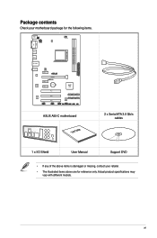
... PCI1 PCI2 PCI3 USB910 SATA3G_2 SATA3G_4 SATA3G_6 SATA3G_1 SATA3G_3 SATA3G_5 64Mb BIOS USB78 USBPW7~10 F_PANEL SPEAKER CHASSIS CLRTC ASUS A55-C motherboard User Guide 2 x Serial ATA 3.0 Gb/s cables 1 x I/O Shield User Manual Support DVD • If any of the above items is damaged or missing, contact your ...
... PCI1 PCI2 PCI3 USB910 SATA3G_2 SATA3G_4 SATA3G_6 SATA3G_1 SATA3G_3 SATA3G_5 64Mb BIOS USB78 USBPW7~10 F_PANEL SPEAKER CHASSIS CLRTC ASUS A55-C motherboard User Guide 2 x Serial ATA 3.0 Gb/s cables 1 x I/O Shield User Manual Support DVD • If any of the above items is damaged or missing, contact your ...
A55-C User's Manual
Page 13
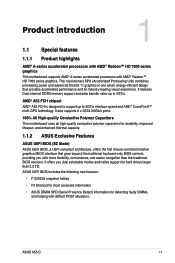
... compliant architecture, offers the first mouse-controlled intuitive graphical BIOS interface that provides accelerated performance and an industry-leading visual experience. ASUS A55-C 1-1 Product introduction 1 1.1 Special features 1.1.1 Product highlights AMD® A-series accelerated processors with AMD® Radeon™...• F3 Shortcut for most accessed information • ASUS DRAM SPD (Serial Presence Detect) information for hard drives larger than the traditional BIOS versions. AMD® A55 FCH chipset AMD® A55 FCH is designed to support up to 5GT/s interface ...
... compliant architecture, offers the first mouse-controlled intuitive graphical BIOS interface that provides accelerated performance and an industry-leading visual experience. ASUS A55-C 1-1 Product introduction 1 1.1 Special features 1.1.1 Product highlights AMD® A-series accelerated processors with AMD® Radeon™...• F3 Shortcut for most accessed information • ASUS DRAM SPD (Serial Presence Detect) information for hard drives larger than the traditional BIOS versions. AMD® A55 FCH chipset AMD® A55 FCH is designed to support up to 5GT/s interface ...
A55-C User's Manual
Page 15
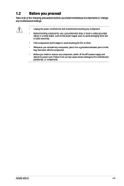
ASUS A55-C 1-3 1.2 Before you proceed Take note of the following precautions before you install motherboard components or change any motherboard settings. • Unplug the power cord from ...
ASUS A55-C 1-3 1.2 Before you proceed Take note of the following precautions before you install motherboard components or change any motherboard settings. • Unplug the power cord from ...
A55-C User's Manual
Page 19
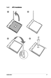
1.4.1 APU installation 1 2 3 4 ASUS A55-C 1-7
1.4.1 APU installation 1 2 3 4 ASUS A55-C 1-7
A55-C User's Manual
Page 21
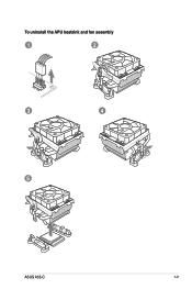
To uninstall the APU heatsink and fan assembly 1 2 3 4 5 ASUS A55-C 1-9
To uninstall the APU heatsink and fan assembly 1 2 3 4 5 ASUS A55-C 1-9

A55-C User's Manual
Page 23
...DS Chip Brand Chip No. DS - - 9-10-9-27 1.50V . . DS - - 10-11-10-30 1.5V . . DS - - - 1.5V . . ASUS A55-C 1-11 DS - - 9-10-9-28 1.5V . . • The default memory operation frequency is dependent on its Serial Presence Detect (SPD), which is the standard way... of accessing information from a memory module. DS - - 9-9-9-24 1.65V . . A55-C Motherboard Qualified Vendors Lists (QVL) DDR3-1866 MHz capability Vendors Part No. DS - - 9-10-9-28 1.5V . . DS - - 9-9-9-24 ...
...DS Chip Brand Chip No. DS - - 9-10-9-27 1.50V . . DS - - 10-11-10-30 1.5V . . DS - - - 1.5V . . ASUS A55-C 1-11 DS - - 9-10-9-28 1.5V . . • The default memory operation frequency is dependent on its Serial Presence Detect (SPD), which is the standard way... of accessing information from a memory module. DS - - 9-9-9-24 1.65V . . A55-C Motherboard Qualified Vendors Lists (QVL) DDR3-1866 MHz capability Vendors Part No. DS - - 9-10-9-28 1.5V . . DS - - 9-9-9-24 ...

A55-C User's Manual
Page 27
1.5.3 1 Installing a DIMM 2 3 To remove a DIMM B A A ASUS A55-C 1-15
1.5.3 1 Installing a DIMM 2 3 To remove a DIMM B A A ASUS A55-C 1-15

A55-C User's Manual
Page 29
shared - - - - - shared - - - shared - - - - - shared - Realtek 8111F controller - ASUS A55-C 1-17 shared - - - - - HD audio shared - - - - - - - Onboard USB1.0 controller - - shared - - shared - - - - - - SATA controller - - - shared - - - - PCIEx1_2 - - PCI1 slot - - - - PCI3 slot - - - - - - IRQ assignments for this motherboard Component A B C D E F G H PCIEx16 - - ...
shared - - - - - shared - - - shared - - - - - shared - Realtek 8111F controller - ASUS A55-C 1-17 shared - - - - - HD audio shared - - - - - - - Onboard USB1.0 controller - - shared - - shared - - - - - - SATA controller - - - shared - - - - PCIEx1_2 - - PCI1 slot - - - - PCI3 slot - - - - - - IRQ assignments for this motherboard Component A B C D E F G H PCIEx16 - - ...
A55-C User's Manual
Page 31
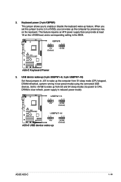
... reduced power mode). Keyboard power (3-pin KBPWR) This jumper allows you can provide at least 1A on the keyboard. KBPWR 12 23 +5V (Default) +5VSB A55-C A55-C Keyboard Power 3. USB device wake-up (3-pin USBPW1~6; 3-pin USBPW7~10) Set these jumpers to +5V to wake up the computer from S3 and S4... sleep modes (no power to wake up +5VSB (Default) ASUS A55-C 1-19 Set to +5VSB to CPU, DRAM in slow refresh, power supply in low power mode) using the connected USB devices. 2.
... reduced power mode). Keyboard power (3-pin KBPWR) This jumper allows you can provide at least 1A on the keyboard. KBPWR 12 23 +5V (Default) +5VSB A55-C A55-C Keyboard Power 3. USB device wake-up (3-pin USBPW1~6; 3-pin USBPW7~10) Set these jumpers to +5V to wake up the computer from S3 and S4... sleep modes (no power to wake up +5VSB (Default) ASUS A55-C 1-19 Set to +5VSB to CPU, DRAM in slow refresh, power supply in low power mode) using the connected USB devices. 2.
A55-C User's Manual
Page 33
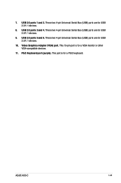
PS/2 Keyboard port (purple). This port is for a VGA monitor or other VGA-compatible devices. 11. These two 4-pin Universal Serial Bus (USB) ports are for USB 2.0/1.1 devices. 8. These two 4-pin Universal Serial Bus (USB) ports are for USB 2.0/1.1 devices. 10. These two 4-pin Universal Serial Bus (USB) ports are for a PS/2 keyboard. USB 2.0 ports 1 and 2. USB 2.0 ports 5 and 6. 7. This 15-pin port is for USB 2.0/1.1 devices. 9. ASUS A55-C 1-21 Video Graphics Adapter (VGA) port. USB 2.0 ports 3 and 4.
PS/2 Keyboard port (purple). This port is for a VGA monitor or other VGA-compatible devices. 11. These two 4-pin Universal Serial Bus (USB) ports are for USB 2.0/1.1 devices. 8. These two 4-pin Universal Serial Bus (USB) ports are for USB 2.0/1.1 devices. 10. These two 4-pin Universal Serial Bus (USB) ports are for a PS/2 keyboard. USB 2.0 ports 1 and 2. USB 2.0 ports 5 and 6. 7. This 15-pin port is for USB 2.0/1.1 devices. 9. ASUS A55-C 1-21 Video Graphics Adapter (VGA) port. USB 2.0 ports 3 and 4.
A55-C User's Manual
Page 35
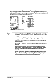
... power output when configuring a system with 20-pin and 4-pin power plugs, ensure that the 20-pin power plug can provide at http://support.asus. 2. The plugs from the power supply are uncertain about the minimum power supply requirement for your system, refer to the Recommended Power Supply Wattage...minimum of 300W. This PSU type has 24-pin and 4-pin power plugs. • If you intend to fit these connectors in only one orientation. ASUS A55-C 1-23 The system may become unstable or may not boot up if the power is inadequate. • DO NOT forget to install additional devices. ...
... power output when configuring a system with 20-pin and 4-pin power plugs, ensure that the 20-pin power plug can provide at http://support.asus. 2. The plugs from the power supply are uncertain about the minimum power supply requirement for your system, refer to the Recommended Power Supply Wattage...minimum of 300W. This PSU type has 24-pin and 4-pin power plugs. • If you intend to fit these connectors in only one orientation. ASUS A55-C 1-23 The system may become unstable or may not boot up if the power is inadequate. • DO NOT forget to install additional devices. ...
A55-C User's Manual
Page 37
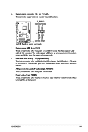
...-mounted functions. F_PANEL PWR LED PWR BTN PLED+ PLEDPWR GND HD_LED+ HD_LED- Connect the HDD Activity LED cable to this connector. 4. ASUS A55-C 1-25 Ground HWRST# (NC) A55-C PIN 1 +HD_LED RESET A55-C System panel connector • System power LED (2-pin PLED) This 2-pin connector is for the chassis-mounted reset button for system reboot...
...-mounted functions. F_PANEL PWR LED PWR BTN PLED+ PLEDPWR GND HD_LED+ HD_LED- Connect the HDD Activity LED cable to this connector. 4. ASUS A55-C 1-25 Ground HWRST# (NC) A55-C PIN 1 +HD_LED RESET A55-C System panel connector • System power LED (2-pin PLED) This 2-pin connector is for the chassis-mounted reset button for system reboot...
A55-C User's Manual
Page 39
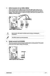
....0 connectors Never connect a 1394 cable to hear system beeps and warnings. +5V GND GND Speaker Out SPEAKER A55-C PIN 1 A55-C Speaker Out Connector ASUS A55-C 1-27 The speaker allows you to the USB connectors. Speaker connector (4-pin SPEAKER) This 4-pin connector is purchased separately. 8. Connect the USB module cable to ...
....0 connectors Never connect a 1394 cable to hear system beeps and warnings. +5V GND GND Speaker Out SPEAKER A55-C PIN 1 A55-C Speaker Out Connector ASUS A55-C 1-27 The speaker allows you to the USB connectors. Speaker connector (4-pin SPEAKER) This 4-pin connector is purchased separately. 8. Connect the USB module cable to ...

A55-C User's Manual
Page 42
... to switch to the USB port. 2. Follow the onscreen instructions to complete the updating process. 2.1.2 ASUS EZ Flash 2 The ASUS EZ Flash 2 feature allows you wish to prevent system boot failure! 2-2 ASUS A55-C Press the Up/Down arrow keys to find the USB flash disk that you to update the BIOS...click Open. 3. c. b. Insert the USB flash disk that contains the latest BIOS file to the Drive field. 4. Updating from the ASUS website at www.asus.com. Press to switch to enable it. 3. Enter the Advanced Mode of updating itself through the Internet. Go to the Tool menu to...
... to switch to the USB port. 2. Follow the onscreen instructions to complete the updating process. 2.1.2 ASUS EZ Flash 2 The ASUS EZ Flash 2 feature allows you wish to prevent system boot failure! 2-2 ASUS A55-C Press the Up/Down arrow keys to find the USB flash disk that you to update the BIOS...click Open. 3. c. b. Insert the USB flash disk that contains the latest BIOS file to the Drive field. 4. Updating from the ASUS website at www.asus.com. Press to switch to enable it. 3. Enter the Advanced Mode of updating itself through the Internet. Go to the Tool menu to...

A55-C User's Manual
Page 44
... 1. Insert the USB flash drive with the latest BIOS file and BIOS Updater to show the BIOS Boot Device Select Menu. C:\>d: D:\> 2-4 ASUS A55-C The actual utility screen displays may not be same as the boot device. Turn off the computer and disconnect all SATA hard disk drives (optional...Insert the support DVD into the optical drive and select the optical drive as shown. The succeeding utility screens are for reference only. When the ASUS Logo appears, press to the USB port. 2. When the Make Disk menu appears, select the FreeDOS command prompt item by pressing the item...
... 1. Insert the USB flash drive with the latest BIOS file and BIOS Updater to show the BIOS Boot Device Select Menu. C:\>d: D:\> 2-4 ASUS A55-C The actual utility screen displays may not be same as the boot device. Turn off the computer and disconnect all SATA hard disk drives (optional...Insert the support DVD into the optical drive and select the optical drive as shown. The succeeding utility screens are for reference only. When the ASUS Logo appears, press to the USB port. 2. When the Make Disk menu appears, select the FreeDOS command prompt item by pressing the item...
A55-C User's Manual
Page 46
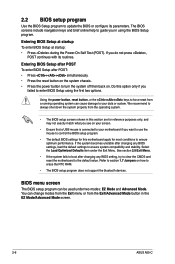
... can change modes from the Exit menu or from the operating system. • The BIOS setup screens shown in the EZ Mode/Advanced Mode screen. 2-6 ASUS A55-C You can cause damage to update the BIOS or configure its routines. 2.2 BIOS setup program Use the BIOS Setup program to your motherboard if you...
... can change modes from the Exit menu or from the operating system. • The BIOS setup screens shown in the EZ Mode/Advanced Mode screen. 2-6 ASUS A55-C You can cause damage to update the BIOS or configure its routines. 2.2 BIOS setup program Use the BIOS Setup program to your motherboard if you...

A55-C User's Manual
Page 48
...bar Navigation keys Menu bar The menu bar on top of the Advanced Mode. To access the EZ Mode, click Exit, then select ASUS EZ Mode. Refer to configure the BIOS settings. The figure below shows an example of the screen has the following sections for special ...functions For selecting the exit options and loading default settings 2-8 ASUS A55-C Advanced Mode The Advanced Mode provides advanced options for experienced end-users to the following main items: Main Ai Tweaker Advanced Monitor Boot Tool...
...bar Navigation keys Menu bar The menu bar on top of the Advanced Mode. To access the EZ Mode, click Exit, then select ASUS EZ Mode. Refer to configure the BIOS settings. The figure below shows an example of the screen has the following sections for special ...functions For selecting the exit options and loading default settings 2-8 ASUS A55-C Advanced Mode The Advanced Mode provides advanced options for experienced end-users to the following main items: Main Ai Tweaker Advanced Monitor Boot Tool...
A55-C User's Manual
Page 50
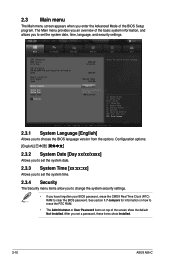
2.3 Main menu The Main menu screen appears when you enter the Advanced Mode of the screen show Installed. 2-10 ASUS A55-C After you set a password, these items show the default Not Installed. Configuration options: [English 2.3.2 System Date [Day xx/xx/xxxx] Allows you to set the ...
2.3 Main menu The Main menu screen appears when you enter the Advanced Mode of the screen show Installed. 2-10 ASUS A55-C After you set a password, these items show the default Not Installed. Configuration options: [English 2.3.2 System Date [Day xx/xx/xxxx] Allows you to set the ...
A55-C User's Manual
Page 52
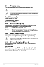
... to enable or disable the EPU power saving function. Configuration options: [Auto] [Light Power Saving Mode] [Medium Power Saving Mode] [Max Power Saving Mode] 2-12 ASUS A55-C The configuration options for the system. [D.O.C.P.] If you install memory modules supporting the eXtreme Memory Profile (D.O.C.P.) technology, select this item to set the memory operating...
... to enable or disable the EPU power saving function. Configuration options: [Auto] [Light Power Saving Mode] [Medium Power Saving Mode] [Max Power Saving Mode] 2-12 ASUS A55-C The configuration options for the system. [D.O.C.P.] If you install memory modules supporting the eXtreme Memory Profile (D.O.C.P.) technology, select this item to set the memory operating...
A55-C User's Manual
Page 54
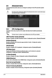
... CPU-related information that the BIOS automatically detects. Configuration options: [Enabled] [Disabled] Bank Interleaving [Enabled] Enables or disables Bank Interleaving. Configuration options: [Enabled] [Disabled] 2-14 ASUS A55-C
... CPU-related information that the BIOS automatically detects. Configuration options: [Enabled] [Disabled] Bank Interleaving [Enabled] Enables or disables Bank Interleaving. Configuration options: [Enabled] [Disabled] 2-14 ASUS A55-C


