
X223W LCD Service Guide
Page 2
Important Safety Notice ACER X223W 1 Go to cover page Product Anouncement: This product is recommended when the situation to replace defective parts. Using Lead-Free solder to an authorized power ... this service manual in the degree of personal injury when perform service procedures. To prevent the product away from water or explosed in assembly and disassembly procedures to minimize the risk of 220°C. To ensure using a proper screwdriver, follow the torque and force listed in extremely high humility environment. ! The...
Important Safety Notice ACER X223W 1 Go to cover page Product Anouncement: This product is recommended when the situation to replace defective parts. Using Lead-Free solder to an authorized power ... this service manual in the degree of personal injury when perform service procedures. To prevent the product away from water or explosed in assembly and disassembly procedures to minimize the risk of 220°C. To ensure using a proper screwdriver, follow the torque and force listed in extremely high humility environment. ! The...
X223W LCD Service Guide
Page 13
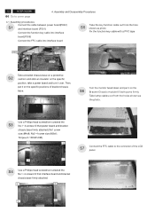
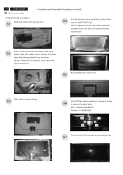
... screwdriver screwed the S3 No.1~4 screws till that interface board and bracket chassis base firmly attached. 3 2 Connect the FFC cable to cover page 4. Assembly and Disassembly Procedures 4.1 Assembly procedures: Connect the cable between power board(P802) S1 and interface board (P301) Connect the function key cable into interface board(P306) Connect... turn it on the S6 Bracket Chassis module till both parts firmly Take lamp cables out from the hole S5 shown as the photo. 12 ACER X223W Go to the connector of bracket chassis base.
... screwdriver screwed the S3 No.1~4 screws till that interface board and bracket chassis base firmly attached. 3 2 Connect the FFC cable to cover page 4. Assembly and Disassembly Procedures 4.1 Assembly procedures: Connect the cable between power board(P802) S1 and interface board (P301) Connect the function key cable into interface board(P306) Connect... turn it on the S6 Bracket Chassis module till both parts firmly Take lamp cables out from the hole S5 shown as the photo. 12 ACER X223W Go to the connector of bracket chassis base.
X223W LCD Service Guide
Page 14
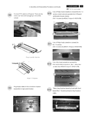
....(Both of right and left sides) S13 Take a key function board to hook with front bezel (No.1~2) and connect to LCD panel. Assembly and Disassembly Procedures (continued) ACER X223W 13 Go to cover page S8 Connect FFC cable to key function cable. 1 2 There are two locks over here when plugging in parallel direction...
....(Both of right and left sides) S13 Take a key function board to hook with front bezel (No.1~2) and connect to LCD panel. Assembly and Disassembly Procedures (continued) ACER X223W 13 Go to cover page S8 Connect FFC cable to key function cable. 1 2 There are two locks over here when plugging in parallel direction...
X223W LCD Service Guide
Page 15
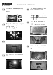
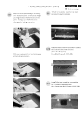
Take a PE bag to cover the LCD monitor. Stick a screen card on force mechanisms locked and firmly attached. Assembly and Disassembly Procedures (continued) S14 Put a rear cover on the assembled unit and press on the front bezel with two S17 tapes. S19 Take a LDPE+EPE bag ...to cover the stand base. 3 1 4 2 Assemble the hinge cover into both units firmly attached. (No1~4 Screw Size=M4x10; Torque=11~13KGFxCM). 14 ACER X223W Go to the rear cover through the way of LCD monitor, and another is held the back side. Stick Vista and TC003 label on the...
Take a PE bag to cover the LCD monitor. Stick a screen card on force mechanisms locked and firmly attached. Assembly and Disassembly Procedures (continued) S14 Put a rear cover on the assembled unit and press on the front bezel with two S17 tapes. S19 Take a LDPE+EPE bag ...to cover the stand base. 3 1 4 2 Assemble the hinge cover into both units firmly attached. (No1~4 Screw Size=M4x10; Torque=11~13KGFxCM). 14 ACER X223W Go to the rear cover through the way of LCD monitor, and another is held the back side. Stick Vista and TC003 label on the...
X223W LCD Service Guide
Page 16
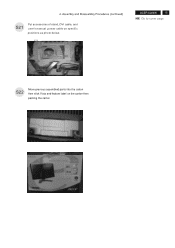
USER'S MANUAL ACER X223W 15 Go to cover page POWER CABLE DVI CABLE STAND D-SUB CABLE S22 Move previous assembled parts into the carton then stick Vista and feature label on specific positions as photo below. Assembly and Disassembly Procedures (continued) S21 Put accessories of stand, DVI cable, and user's manual ,power cable on the carton then packing the carton FEATURE LABEL VISTA LABEL 4.
USER'S MANUAL ACER X223W 15 Go to cover page POWER CABLE DVI CABLE STAND D-SUB CABLE S22 Move previous assembled parts into the carton then stick Vista and feature label on specific positions as photo below. Assembly and Disassembly Procedures (continued) S21 Put accessories of stand, DVI cable, and user's manual ,power cable on the carton then packing the carton FEATURE LABEL VISTA LABEL 4.
X223W LCD Service Guide
Page 17
... depends on a protective cushion,then remove LDPE+EPE bag. Assembly and Disassembly Procedures (continued) 4.2 Disassembly procedures Open the carton with a proper tool. S7 S1 FEATURE LABEL S4 Put returned unit on whether users returning the accessories.) USER'S MANUAL Disassemble the stand cover. 16 ACER X223W Go to release the stand base. (No1~4 Screw Size=M4x10;
... depends on a protective cushion,then remove LDPE+EPE bag. Assembly and Disassembly Procedures (continued) 4.2 Disassembly procedures Open the carton with a proper tool. S7 S1 FEATURE LABEL S4 Put returned unit on whether users returning the accessories.) USER'S MANUAL Disassemble the stand cover. 16 ACER X223W Go to release the stand base. (No1~4 Screw Size=M4x10;
X223W LCD Service Guide
Page 18
Assembly and Disassembly Procedures (continued) ACER X223W 17 Go to cover page Place cloth on the panel where you are working S8 on the front bezel to disengage all the locking mechanism. ...
Assembly and Disassembly Procedures (continued) ACER X223W 17 Go to cover page Place cloth on the panel where you are working S8 on the front bezel to disengage all the locking mechanism. ...
X223W LCD Service Guide
Page 19
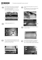
18 ACER X223W Go to release the interface board. (No1~4 screw size=M3x6; Put it aside. S17 Use a Phillips-head screwdriver unscrewed the No.1~4 screws to cover page 4. ...=3~4KGFxCM). S14 Take out lamp cables right through the No.1 and 2 square holes and separate the bracket chassis module and LCD panel apart. Assembly and Disassembly Procedures (continued) S12 Use a Phillips-head screwdriver unscrewed the No.1~4 screws to the connector of panel. S15 Disconnect the FFC cable to...
18 ACER X223W Go to release the interface board. (No1~4 screw size=M3x6; Put it aside. S17 Use a Phillips-head screwdriver unscrewed the No.1~4 screws to cover page 4. ...=3~4KGFxCM). S14 Take out lamp cables right through the No.1 and 2 square holes and separate the bracket chassis module and LCD panel apart. Assembly and Disassembly Procedures (continued) S12 Use a Phillips-head screwdriver unscrewed the No.1~4 screws to the connector of panel. S15 Disconnect the FFC cable to...
X223W LCD Service Guide
Page 20
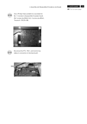
No2~4 screw size=M3x6; Torque=9~10KGFxCM). 3 2 ACER X223W 19 Go to cover page 4 1 Disconnect the FFC, P301, and function key S19 cables to disassemble the power board. (No1 screw size=M4x8; Assembly and Disassembly Procedures (continued) S18 Use a Phillips-head screwdriver unscrewed the No.1~4 screws to connectors of interface board. P802 P301 FFC P306 4.
No2~4 screw size=M3x6; Torque=9~10KGFxCM). 3 2 ACER X223W 19 Go to cover page 4 1 Disconnect the FFC, P301, and function key S19 cables to disassemble the power board. (No1 screw size=M4x8; Assembly and Disassembly Procedures (continued) S18 Use a Phillips-head screwdriver unscrewed the No.1~4 screws to connectors of interface board. P802 P301 FFC P306 4.


