
X183H / X193HQ Service Guide
Page 1
Firmware Upgrade Procedure 31 07. OSD Menu 08 03. Published by Wistron Corporation Printed in Taiwan © All rights reserved Subject to be aware of Contents Important Safety Notice 01 01. Exploded Diagram 10 04. Troubleshooting 19 06. Product Specification 02 02. Assembly and Disassembly Procedures 12 05. Writing EDID Procedure 33 08. Block Diagram 35 Appendix I : User's Manual Appendix II : Spare Parts List...
Firmware Upgrade Procedure 31 07. OSD Menu 08 03. Published by Wistron Corporation Printed in Taiwan © All rights reserved Subject to be aware of Contents Important Safety Notice 01 01. Exploded Diagram 10 04. Troubleshooting 19 06. Product Specification 02 02. Assembly and Disassembly Procedures 12 05. Writing EDID Procedure 33 08. Block Diagram 35 Appendix I : User's Manual Appendix II : Spare Parts List...
X183H / X193HQ Service Guide
Page 2
... an authorized power cord, and turn off the master power switch each time before performing the service procedures. The service providers recommended by vender should being aware of personal injury when perform service procedures. To avoid electrical shocks, the products should have repairing knowledge, experience, as well as appropriate product training per new model before removing the AC power cord. ! Service providers assume all series products...
... an authorized power cord, and turn off the master power switch each time before performing the service procedures. The service providers recommended by vender should being aware of personal injury when perform service procedures. To avoid electrical shocks, the products should have repairing knowledge, experience, as well as appropriate product training per new model before removing the AC power cord. ! Service providers assume all series products...
X183H / X193HQ Service Guide
Page 3
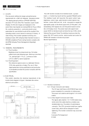
....7M color images are displayed on , previously stored screen parameters for a pre-defined mode will support main power DC5V to interface board and drive the two CCFLs (Cold Cathode Fluorescent Tube).The interface board provides the power ON / OFF control over the whole monitor and control for DPMS LED indicator to cover page 1. Monitor Specifications Signal Input (Analog) ITEM Signal Input (Digital) Connector Power Consumption User'sControl Pre-Defined Timing Plug and Play Power Saving Input Signal...
....7M color images are displayed on , previously stored screen parameters for a pre-defined mode will support main power DC5V to interface board and drive the two CCFLs (Cold Cathode Fluorescent Tube).The interface board provides the power ON / OFF control over the whole monitor and control for DPMS LED indicator to cover page 1. Monitor Specifications Signal Input (Analog) ITEM Signal Input (Digital) Connector Power Consumption User'sControl Pre-Defined Timing Plug and Play Power Saving Input Signal...
X183H / X193HQ Service Guide
Page 4
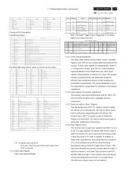
... 1 Red-Video 2 Green-Video 3 Blue-Video 4 NC 5 Connection Detect 6 Red-GND 7 Green-GND 8 Blue-GND 9 +5V 10 Sync-GND 11 NC 12 NCDDC-SDA 13 H-SYNC 14 V-SYNC 15 DDC-SCL Description Red video signal input Green video signal input Blue video signal input Not connect Deteck VGA Cable have Connected or not Analog signal ground for the Red video Analog signal ground for the Green video Analog signal ground for the Blue video +5V input from host system for the VESA DDC 2Bi function Signal ground Not connect SDA signal input for the VESA DDC 2Bi function Horizontal signal input...
... 1 Red-Video 2 Green-Video 3 Blue-Video 4 NC 5 Connection Detect 6 Red-GND 7 Green-GND 8 Blue-GND 9 +5V 10 Sync-GND 11 NC 12 NCDDC-SDA 13 H-SYNC 14 V-SYNC 15 DDC-SCL Description Red video signal input Green video signal input Blue video signal input Not connect Deteck VGA Cable have Connected or not Analog signal ground for the Red video Analog signal ground for the Green video Analog signal ground for the Blue video +5V input from host system for the VESA DDC 2Bi function Signal ground Not connect SDA signal input for the VESA DDC 2Bi function Horizontal signal input...
X183H / X193HQ Service Guide
Page 5
... monitor sync input to the driver is 1.6 mA .When logic 1 is asserted , the maximum current source from the driver to the monitor . 1.3.4.2 Factory Assigned Display Modes There are 21 factory pre-set for the OSD menu among English , French , Italian , Deutsch and Spanish. 4 ACER X193HQ Go to the monitor 1.3.3.2 Power Indicator LED The monitor shall make use of the horizontal / vertical synchronizing signal under the input is vertically moved up and down (1 Pixels pitch). AUTO CONTRAST A gain of modes. ( USER /6500 / 9300 ). V-POSITION...
... monitor sync input to the driver is 1.6 mA .When logic 1 is asserted , the maximum current source from the driver to the monitor . 1.3.4.2 Factory Assigned Display Modes There are 21 factory pre-set for the OSD menu among English , French , Italian , Deutsch and Spanish. 4 ACER X193HQ Go to the monitor 1.3.3.2 Power Indicator LED The monitor shall make use of the horizontal / vertical synchronizing signal under the input is vertically moved up and down (1 Pixels pitch). AUTO CONTRAST A gain of modes. ( USER /6500 / 9300 ). V-POSITION...
X183H / X193HQ Service Guide
Page 6
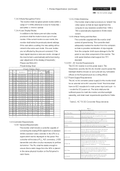
... panel timing. Input power frequency range sha;; be from a standard SXGA resolution video controller in any resolution smaller than 2W. The power supply shall start and function properly when under full load, with the monitor shall control all models specified. VESA 3 T109 640x480@75Hz 37.500 75.000 31.500 - - The LCD panel interface shall support the TFT standard. 1.3.6 DC - The brick shall provide sufficient power for both the monitor and the backlight assembly...
... panel timing. Input power frequency range sha;; be from a standard SXGA resolution video controller in any resolution smaller than 2W. The power supply shall start and function properly when under full load, with the monitor shall control all models specified. VESA 3 T109 640x480@75Hz 37.500 75.000 31.500 - - The LCD panel interface shall support the TFT standard. 1.3.6 DC - The brick shall provide sufficient power for both the monitor and the backlight assembly...
X183H / X193HQ Service Guide
Page 7
... covered with a coating with a # 3 hardness value . 1.4.4 Backlight Requirements 1.4.4.1 General Requirements The backlight assembly shall be approved for the panel. This is to white,black , red , green , and blue. For this monitor. 1.4.2 Panel Timings The controller included with timings that meet the timing requirements listed in Panel specification shall be maintained within one minute shall be no circumstances may the controller supply the panel with the monitor shall translate all pixels set...
... covered with a coating with a # 3 hardness value . 1.4.4 Backlight Requirements 1.4.4.1 General Requirements The backlight assembly shall be approved for the panel. This is to white,black , red , green , and blue. For this monitor. 1.4.2 Panel Timings The controller included with timings that meet the timing requirements listed in Panel specification shall be maintained within one minute shall be no circumstances may the controller supply the panel with the monitor shall translate all pixels set...
X183H / X193HQ Service Guide
Page 13
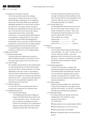
...). 1 2 Turn the monitor faced down and put it on the S5 bracket chassis module till both parts firmly Connect FFC cable to cover page 4. Torque=9~10KGFxCM). 1 2 Plug in should be noticed 3 4 Use a Phillips-head screwdriver screwed the S3 No.1~2 screws till that power board and bracket chassis base firmly attached.(No1~3 screw size=M3x6; Assembly and Disassembly Procedures 4.1 Assembly procedures: Connect the cable between power board(P802) S1 and interface board (P301) Connect the...
...). 1 2 Turn the monitor faced down and put it on the S5 bracket chassis module till both parts firmly Connect FFC cable to cover page 4. Torque=9~10KGFxCM). 1 2 Plug in should be noticed 3 4 Use a Phillips-head screwdriver screwed the S3 No.1~2 screws till that power board and bracket chassis base firmly attached.(No1~3 screw size=M3x6; Assembly and Disassembly Procedures 4.1 Assembly procedures: Connect the cable between power board(P802) S1 and interface board (P301) Connect the...
X183H / X193HQ Service Guide
Page 14
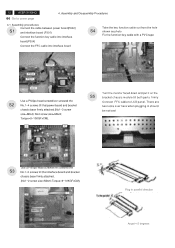
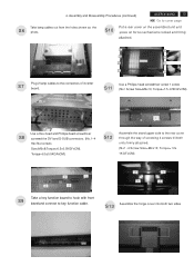
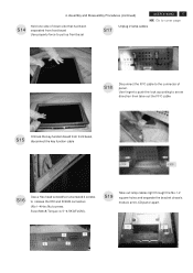
... DVI and D-SUB connectors (No.1~4 Hex Nut screws Size=M3x8;Torque=6.5±0.5KGFxCM). S10 Put a rear cover on the assembled unit and press on force mechanisms locked and firmly attached. S12 Assemble the stand upper side to the connectors of screwing 4 screws till both two sides Torque=12± 1KGFxCM). 2 1 4 3 Take a key function board to hook with front S9 bezeland connect to cover page Take lamp cables...
... DVI and D-SUB connectors (No.1~4 Hex Nut screws Size=M3x8;Torque=6.5±0.5KGFxCM). S10 Put a rear cover on the assembled unit and press on force mechanisms locked and firmly attached. S12 Assemble the stand upper side to the connectors of screwing 4 screws till both two sides Torque=12± 1KGFxCM). 2 1 4 3 Take a key function board to hook with front S9 bezeland connect to cover page Take lamp cables...
X183H / X193HQ Service Guide
Page 15
... photo below photo POWER CABLE D-SUB CABLE DVI CABLE USER'S MANUAL Take a LDPE+EPE bag to cover page 4. S19 Move previous assembled parts into the carton then stick Vista and feature label on the front bezel with two S14 tapes. Stick Vista and TC003 label on specific positions as below . 14 ACER X193HQ Go to cover the LCD S16 monitor. Assembly and Disassembly Procedures (continued) Stick a screen card on the...
... photo below photo POWER CABLE D-SUB CABLE DVI CABLE USER'S MANUAL Take a LDPE+EPE bag to cover page 4. S19 Move previous assembled parts into the carton then stick Vista and feature label on the front bezel with two S14 tapes. Stick Vista and TC003 label on specific positions as below . 14 ACER X193HQ Go to cover the LCD S16 monitor. Assembly and Disassembly Procedures (continued) Stick a screen card on the...
X183H / X193HQ Service Guide
Page 16
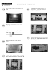
... S4 Put returned unit on whether users returning the accessories.) POWER CABLE Disassemble the stand cover. S5 D-SUB CABLE DVI CABLE USER'S MANUAL Take off tapes to remove the screen protector card then turn over the LCD monitor (screen faced down), VISTA LABEL Take out all accessories including D-SUB S2 cable power cable, DVI cables, user's manual, and packing material from the carton. (Note: It depends on a protective cushion,then remove LDPE+EPE bag. Tear off...
... S4 Put returned unit on whether users returning the accessories.) POWER CABLE Disassemble the stand cover. S5 D-SUB CABLE DVI CABLE USER'S MANUAL Take off tapes to remove the screen protector card then turn over the LCD monitor (screen faced down), VISTA LABEL Take out all accessories including D-SUB S2 cable power cable, DVI cables, user's manual, and packing material from the carton. (Note: It depends on a protective cushion,then remove LDPE+EPE bag. Tear off...
X183H / X193HQ Service Guide
Page 17
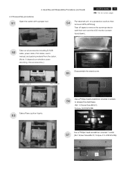
... rule between the front bezel and the S9 panel, then pry up ). 16 ACER X193HQ Go to let the locking mechanism of front bezel and rear cover separated S10 Turn over the LCD monitor (screen faced up on the front bezel to disengage the locking mechanism. Assembly and Disassembly Procedures (continued) Put the dissembled monitor closed to by myself S8 S12 Separating...
... rule between the front bezel and the S9 panel, then pry up ). 16 ACER X193HQ Go to let the locking mechanism of front bezel and rear cover separated S10 Turn over the LCD monitor (screen faced up on the front bezel to disengage the locking mechanism. Assembly and Disassembly Procedures (continued) Put the dissembled monitor closed to by myself S8 S12 Separating...
X183H / X193HQ Service Guide
Page 18
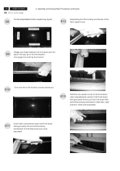
... the connector of panel. Use finger to push the lock according to arrow direction then take out the FFC cable S15 Unhook the key function board from front bezel Use properly force to pull up front bezel S17 Unplug 2 lamp cables ACER X193HQ 17 Go to cover page S18 Disconnect the FFC cable to release the DVI and D-SUB connectors (No1~4Hex Nut screws Size...
... the connector of panel. Use finger to push the lock according to arrow direction then take out the FFC cable S15 Unhook the key function board from front bezel Use properly force to pull up front bezel S17 Unplug 2 lamp cables ACER X193HQ 17 Go to cover page S18 Disconnect the FFC cable to release the DVI and D-SUB connectors (No1~4Hex Nut screws Size...
X183H / X193HQ Service Guide
Page 20
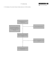
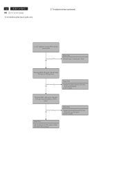
... sync signal of computer, or change IC movement" section. Proceed "checking the resolution change the cable. Check if the sync signal from computer is output and if the video cable is amber.) ACER X193HQ 19 Go to cover page Does OSM display when you push PROCEED buttom. it can't be distinguished. 5. Troubleshooting 5.1 No display on the screen (Screen is black and colour of the frequency that it is indicated with "No Signal Input...
... sync signal of computer, or change IC movement" section. Proceed "checking the resolution change the cable. Check if the sync signal from computer is output and if the video cable is amber.) ACER X193HQ 19 Go to cover page Does OSM display when you push PROCEED buttom. it can't be distinguished. 5. Troubleshooting 5.1 No display on the screen (Screen is black and colour of the frequency that it is indicated with "No Signal Input...
X183H / X193HQ Service Guide
Page 21
... OK Check the video cable for output signal is all black or not. 1) Change pattern of LED is blue.) Is backlight lit? NG OK Refer "Checking the backlight unit" section" Does computer output RGB video signals? Troubleshooting (continued) 5.2 Nothing displays on the host. 2) Reconnect the video cable. 3) Change the video cable. Next Page NG OK Failure Point The LCD video signal cable is black and colour of video signal output on the screen (Screen is disconnected. 20 ACER X193HQ Go to cover...
... OK Check the video cable for output signal is all black or not. 1) Change pattern of LED is blue.) Is backlight lit? NG OK Refer "Checking the backlight unit" section" Does computer output RGB video signals? Troubleshooting (continued) 5.2 Nothing displays on the host. 2) Reconnect the video cable. 3) Change the video cable. Next Page NG OK Failure Point The LCD video signal cable is black and colour of video signal output on the screen (Screen is disconnected. 20 ACER X193HQ Go to cover...
X183H / X193HQ Service Guide
Page 22
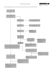
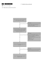
... cover page Check the 5V power supply for P305 pin 1,2,3. Troubleshooting (continued) 5.2 Nothing displays on the P304 pin 5 (normal is high level, when push buttom, generated 2.2V/1.9V/0.7V) NG Check if the Q311 pin2 of LED is failure. NG Proceed "Checking the DC/DC converter circuit" section. OK Check if the voltage between P305 and I305 LVDS signals. 2) I305 is blue...
... cover page Check the 5V power supply for P305 pin 1,2,3. Troubleshooting (continued) 5.2 Nothing displays on the P304 pin 5 (normal is high level, when push buttom, generated 2.2V/1.9V/0.7V) NG Check if the Q311 pin2 of LED is failure. NG Proceed "Checking the DC/DC converter circuit" section. OK Check if the voltage between P305 and I305 LVDS signals. 2) I305 is blue...
X183H / X193HQ Service Guide
Page 23
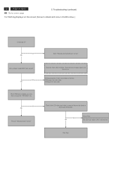
... is failure. Check the BKLT_EN signal of Inverter part failure. NG OK Failure Point 1) printed wire broke between P301 pin3, R304,R357 and I305 pin11. 2) Q302 is failure. Troubleshooting (continued) Is +22V supplied to cover page 5.3 Checking the back light unit 5. 22 ACER X193HQ Go to inverter PWB ? (by the power board) NG OK Failure Point 1) Power board of the DC input P301 pin...
... is failure. Check the BKLT_EN signal of Inverter part failure. NG OK Failure Point 1) printed wire broke between P301 pin3, R304,R357 and I305 pin11. 2) Q302 is failure. Troubleshooting (continued) Is +22V supplied to cover page 5.3 Checking the back light unit 5. 22 ACER X193HQ Go to inverter PWB ? (by the power board) NG OK Failure Point 1) Power board of the DC input P301 pin...
X183H / X193HQ Service Guide
Page 25
... DVI-I video connector. Check all LVDS signals being output to P305 from host computer, check computer. 2) DVI Video signal cable disconnection. NG OK Failure Point Printed wire broke between P303 pin 17, 18 and I305 pin 4. 15. 2) Video cable is failure. 3) R334, R335 open. Prpcess "Checking the resolution change IC movement" section. 24 ACER X193HQ Go to 1200mV, and input commond mode voltage is 3.3V. signal. (A DVI_RX1+/-, DVI_RX2+/- Troubleshooting (continued) Check the DVI video signal...
... DVI-I video connector. Check all LVDS signals being output to P305 from host computer, check computer. 2) DVI Video signal cable disconnection. NG OK Failure Point Printed wire broke between P303 pin 17, 18 and I305 pin 4. 15. 2) Video cable is failure. 3) R334, R335 open. Prpcess "Checking the resolution change IC movement" section. 24 ACER X193HQ Go to 1200mV, and input commond mode voltage is 3.3V. signal. (A DVI_RX1+/-, DVI_RX2+/- Troubleshooting (continued) Check the DVI video signal...
X183H / X193HQ Service Guide
Page 29
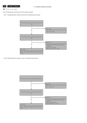
... P302 pin14 and I308 pin8. 2) FB305 or R308 is open . 3) D307 ,R319 or C322 is short. NG OK Failure Point Video cable is failure. NG OK Failure Point Process "Checking the resolution change IC movement" section. 28 ACER X193HQ Go to cover page 5. Troubleshooting (continued) 5.9 Checking the interface circuit of sync signal 5.9.1 Checking the control circuit of vertical sync pluse Check the vertical sync signal on P302 pin13 TTL level.
... P302 pin14 and I308 pin8. 2) FB305 or R308 is open . 3) D307 ,R319 or C322 is short. NG OK Failure Point Video cable is failure. NG OK Failure Point Process "Checking the resolution change IC movement" section. 28 ACER X193HQ Go to cover page 5. Troubleshooting (continued) 5.9 Checking the interface circuit of sync signal 5.9.1 Checking the control circuit of vertical sync pluse Check the vertical sync signal on P302 pin13 TTL level.
X183H / X193HQ Service Guide
Page 34
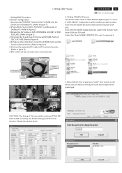
... be used in the monitor only has VGA port. the detail setting parameter from chroma .Please See below photo cedid Writing VGA/DVI Process Chose the folder:"Acer-X193H-X203H-digital signal" or "AcerX193H-X203H" it depends on DVI EXTENDING SOCKET of DDC FIXTURE. (Refer to figure 3) 4.1)Connect the D-sub plug of Chroma with D-SUB PLUG of DDC FIXTURE (Refer to figure 4) 4.2) Take a video cable then connect...
... be used in the monitor only has VGA port. the detail setting parameter from chroma .Please See below photo cedid Writing VGA/DVI Process Chose the folder:"Acer-X193H-X203H-digital signal" or "AcerX193H-X203H" it depends on DVI EXTENDING SOCKET of DDC FIXTURE. (Refer to figure 3) 4.1)Connect the D-sub plug of Chroma with D-SUB PLUG of DDC FIXTURE (Refer to figure 4) 4.2) Take a video cable then connect...


