
AL1906 Service Guide
Page 3
... all necessary servicing, repair, and any warranties of LiteOn Technology Corp. Alerts you to do specific actions relevant to the accomplishment of additional information related to the contents hereof and specifically disclaims any incidental or consequential damages resulting from doing or not doing specific actions. All rights reserved. ACER AL1906 Service Manual. Any Acer Incorporated software described in the software. Acer Incorporated makes no...
... all necessary servicing, repair, and any warranties of LiteOn Technology Corp. Alerts you to do specific actions relevant to the accomplishment of additional information related to the contents hereof and specifically disclaims any incidental or consequential damages resulting from doing or not doing specific actions. All rights reserved. ACER AL1906 Service Manual. Any Acer Incorporated software described in the software. Acer Incorporated makes no...
AL1906 Service Guide
Page 4
... inside the monitor. add-on a circuit different from that to which can radiate radio frequency energy, and if not installed and used in accordance with the emission limits. 3. If, for help. This Service Guide provides you with the limits for Acer's "global" product offering. Warning: (For FCC Certified Models) Note: This equipment has been tested and found to Part 15...
... inside the monitor. add-on a circuit different from that to which can radiate radio frequency energy, and if not installed and used in accordance with the emission limits. 3. If, for help. This Service Guide provides you with the limits for Acer's "global" product offering. Warning: (For FCC Certified Models) Note: This equipment has been tested and found to Part 15...
AL1906 Service Guide
Page 5
... a safety feature. It may find slightly uneven brightness on the screen depending on the desktop pattern you mount the monitor on an unstable trolley, stand, or table. Slots and openings in a wet basement.ff Do not place the monitor on a wall or shelf, uses a mounting kit approved by changing the image or turning off the Power Switch and then turn it will not be sure these...
... a safety feature. It may find slightly uneven brightness on the screen depending on the desktop pattern you mount the monitor on an unstable trolley, stand, or table. Slots and openings in a wet basement.ff Do not place the monitor on a wall or shelf, uses a mounting kit approved by changing the image or turning off the Power Switch and then turn it will not be sure these...
AL1906 Service Guide
Page 6
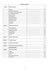
... Requirements LCD Monitor General Specification LCD Panel Specification Support Timing Block Diagram Main Board Diagram Software Flow chart Main Board Layout Front Bezel Rear Bezel Chapter 2 Operating Instructions External Controls Front Panel Controls Adjusting the picture Hot-Key Menu OSD Message LOGO Chapter 3 Machine Disassembly 6 7 8 9 10 11 12 13 15 16 17 18 18 19 20 23 23 24 25 Chapter 4 Troubleshooting 32 Chapter 5 Connector Information 37 Chapter 6 FRU (Field Replacement Unit...
... Requirements LCD Monitor General Specification LCD Panel Specification Support Timing Block Diagram Main Board Diagram Software Flow chart Main Board Layout Front Bezel Rear Bezel Chapter 2 Operating Instructions External Controls Front Panel Controls Adjusting the picture Hot-Key Menu OSD Message LOGO Chapter 3 Machine Disassembly 6 7 8 9 10 11 12 13 15 16 17 18 18 19 20 23 23 24 25 Chapter 4 Troubleshooting 32 Chapter 5 Connector Information 37 Chapter 6 FRU (Field Replacement Unit...
AL1906 Service Guide
Page 7
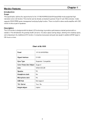
... specification defines the requirements for the 19" MICROPROCESSOR based Multi-mode supported high resolution color LCD monitor. There is a build-in stereo audio amplifier with OSD control to the traditional CRT monitor, it consumes less power and gets less weight in addition MTBF target is 50k hours or more desktop space, and comparing to drive a pair of AL1906 Panel 19" AU M190EN04 Signal Interface D-SUB Sync Type Separate / Compatible Color...
... specification defines the requirements for the 19" MICROPROCESSOR based Multi-mode supported high resolution color LCD monitor. There is a build-in stereo audio amplifier with OSD control to the traditional CRT monitor, it consumes less power and gets less weight in addition MTBF target is 50k hours or more desktop space, and comparing to drive a pair of AL1906 Panel 19" AU M190EN04 Signal Interface D-SUB Sync Type Separate / Compatible Color...
AL1906 Service Guide
Page 8
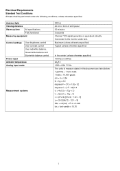
Ambient light Viewing distance Warm up time All specifications Fully functional Measuring equipment Control settings User brightness control User contrast control User red/white balance, Green/white balance and Blue/white balance control Power input Ambient temperature Analog input mode Measurement systems 225 lux 40 cm in front of ... 20+5℃ 1280 x1024 /75 Hz The units of LCD panel 30 minutes 5 seconds Chroma 7120 signal generator or equivalent, directly Connected to the monitor under the following conditions, unless otherwise specified. Electrical Requirements Standard...
Ambient light Viewing distance Warm up time All specifications Fully functional Measuring equipment Control settings User brightness control User contrast control User red/white balance, Green/white balance and Blue/white balance control Power input Ambient temperature Analog input mode Measurement systems 225 lux 40 cm in front of ... 20+5℃ 1280 x1024 /75 Hz The units of LCD panel 30 minutes 5 seconds Chroma 7120 signal generator or equivalent, directly Connected to the monitor under the following conditions, unless otherwise specified. Electrical Requirements Standard...

AL1906 Service Guide
Page 10
LCD Panel Specification LCD Panel Model (AU M190EN04) Display Type active matrix color TFT LCD Resolution 1280x1024 pixels Display Dot 1280x (RGB) x 1024 Display Area 376.32mm(H) x 301.06mm(V) Pixel Pitch 0.294mm(H) x 0.294mm(V) Display Color 16.2M (true) Lamp Frequency 50kHz(Max.) Lamp Current 7.0 mArms (typ.) Weight 2700g (typ.) Optical Specifications Measuring Condition: Ta = 25°C. 9
LCD Panel Specification LCD Panel Model (AU M190EN04) Display Type active matrix color TFT LCD Resolution 1280x1024 pixels Display Dot 1280x (RGB) x 1024 Display Area 376.32mm(H) x 301.06mm(V) Pixel Pitch 0.294mm(H) x 0.294mm(V) Display Color 16.2M (true) Lamp Frequency 50kHz(Max.) Lamp Current 7.0 mArms (typ.) Weight 2700g (typ.) Optical Specifications Measuring Condition: Ta = 25°C. 9

AL1906 Service Guide
Page 12
CCFL Drive. Flat Panel and CCFL backlight Power Board (Inverter, adapter Board) AC-IN 100V-240V Main Board Audio board Keyboard RS232 Connector For white balance adjustment in factory mode HOST Computer Video signal, DDC 11 Monitor Block Diagram The LCD MONITOR will drive the backlight of panel. The Inverter board will contain a main board, a power board, keypad board and audio board which house the flat panel control logic, brightness control logic and DDC.
CCFL Drive. Flat Panel and CCFL backlight Power Board (Inverter, adapter Board) AC-IN 100V-240V Main Board Audio board Keyboard RS232 Connector For white balance adjustment in factory mode HOST Computer Video signal, DDC 11 Monitor Block Diagram The LCD MONITOR will drive the backlight of panel. The Inverter board will contain a main board, a power board, keypad board and audio board which house the flat panel control logic, brightness control logic and DDC.
AL1906 Service Guide
Page 15
... mode? 11) Update the lifetime of brightness from analog port? 16) Display "No connection Check Signal Cable" message. Turn on the LED and set it to show the coming from EEPROM. 5) Is the power key pressed? 6) Clear all global flags. 7) Are the AUTO and SELECT keys pressed? 8) Enter factory mode. 9) Save the power key status into standby mode after the message disappears. 17) Program the scalar to be able to green color...
... mode? 11) Update the lifetime of brightness from analog port? 16) Display "No connection Check Signal Cable" message. Turn on the LED and set it to show the coming from EEPROM. 5) Is the power key pressed? 6) Clear all global flags. 7) Are the AUTO and SELECT keys pressed? 8) Enter factory mode. 9) Save the power key status into standby mode after the message disappears. 17) Program the scalar to be able to green color...
AL1906 Service Guide
Page 17
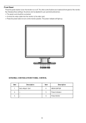
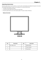
... settings, the picture can be adjusted to your personal preferences. • The power cord should be connected. • Connect the video cable from the monitor to the video card. • Press the power button to turn on or off. EXTERNAL CONTROLS FRONT PANEL CONTROL Item 1. 2. 3. Description MENU/ENTER Power Indicator Power Button 16 The other control buttons are located at front panel of the monitor. Front Bezel Press the power button to turn the monitor on the monitor position, The power indicator will light...
... settings, the picture can be adjusted to your personal preferences. • The power cord should be connected. • Connect the video cable from the monitor to the video card. • Press the power button to turn on or off. EXTERNAL CONTROLS FRONT PANEL CONTROL Item 1. 2. 3. Description MENU/ENTER Power Indicator Power Button 16 The other control buttons are located at front panel of the monitor. Front Bezel Press the power button to turn the monitor on the monitor position, The power indicator will light...
AL1906 Service Guide
Page 19
... settings, the picture can be adjusted to your personal preferences. • The power cord should be connected. • Connect the video cable from the monitor to the video card. • Press the power button to turn on or off. Description MENU/ENTER Power Indicator Power Button 18 The other control buttons are located at front panel of the monitor. Description Auto Adjust / Exit < > Item 4. 5. 6. Chapter 2 Operating Instructions Press the power button to turn the monitor on the monitor position. The power indicator will light...
... settings, the picture can be adjusted to your personal preferences. • The power cord should be connected. • Connect the video cable from the monitor to the video card. • Press the power button to turn on or off. Description MENU/ENTER Power Indicator Power Button 18 The other control buttons are located at front panel of the monitor. Description Auto Adjust / Exit < > Item 4. 5. 6. Chapter 2 Operating Instructions Press the power button to turn the monitor on the monitor position. The power indicator will light...
AL1906 Service Guide
Page 20
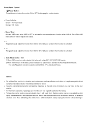
... stains may be removed with a cloth lightly dampened with a soft cloth. When OSD menu is ON or Exit OSD menu when in off status, press this button for 2 seconds to set the HPos, VPos, Clock and Focus. Front Panel Control • /Power Button: Press this button will damage the cabinet. Power on mode. NOTES • Do not install the monitor in a location near heat sources such as radiators...
... stains may be removed with a cloth lightly dampened with a soft cloth. When OSD menu is ON or Exit OSD menu when in off status, press this button for 2 seconds to set the HPos, VPos, Clock and Focus. Front Panel Control • /Power Button: Press this button will damage the cabinet. Power on mode. NOTES • Do not install the monitor in a location near heat sources such as radiators...

AL1906 Service Guide
Page 21
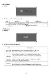
Press the MENU-button to select the function that you want to adjust any other function, repeat steps 2-4. Press to activate the OSD window. 2. Press the MENU-button to select the desired function. 3. To exit and save, select the exit function. Press < or >to Adjust a Setting 1. Analog-Only Mode 20 Adjusting the Picture a. If you want to adjust. 4. How to change the settings of the current function. 5.
Press the MENU-button to select the function that you want to adjust any other function, repeat steps 2-4. Press to activate the OSD window. 2. Press the MENU-button to select the desired function. 3. To exit and save, select the exit function. Press < or >to Adjust a Setting 1. Analog-Only Mode 20 Adjusting the Picture a. If you want to adjust. 4. How to change the settings of the current function. 5.

AL1906 Service Guide
Page 22
.... Position Adjust the horizontal position of the picture. b. User / Red Red Gain from EEPROM. Set OSD display language to Traditional Chinese. Set OSD display language to Spain. Recall Warm Color Temperature from Digital-register. User/ Green Green Gain Digital-register. Position Adjust the vertical position of the picture. Set OSD display language to Italian. Set OSD display language to Japanese. H. Set OSD display language to Simplified Chinese. The Description For Control Function Main Menu Sub Menu Sub Menu Item Icon Icon Contrast...
.... Position Adjust the horizontal position of the picture. b. User / Red Red Gain from EEPROM. Set OSD display language to Traditional Chinese. Set OSD display language to Spain. Recall Warm Color Temperature from Digital-register. User/ Green Green Gain Digital-register. Position Adjust the vertical position of the picture. Set OSD display language to Italian. Set OSD display language to Japanese. H. Set OSD display language to Simplified Chinese. The Description For Control Function Main Menu Sub Menu Sub Menu Item Icon Icon Contrast...
AL1906 Service Guide
Page 23
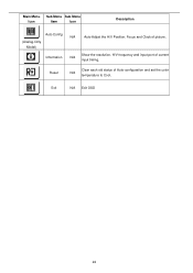
Reset Clear each old status of current N/A input timing. Show the resolution, H/V frequency and input port of Auto-configuration and set the color N/A temperature to Cool. Exit N/A Exit OSD 22 Main Menu Icon Sub Menu Sub Menu Item Icon Description Auto Config (Analog-Only Model) Information N/A Auto Adjust the H/V Position, Focus and Clock of picture.
Reset Clear each old status of current N/A input timing. Show the resolution, H/V frequency and input port of Auto-configuration and set the color N/A temperature to Cool. Exit N/A Exit OSD 22 Main Menu Icon Sub Menu Sub Menu Item Icon Description Auto Config (Analog-Only Model) Information N/A Auto Adjust the H/V Position, Focus and Clock of picture.
AL1906 Service Guide
Page 24
The Description For OSD Message Item Description Auto Config When Analog signal input, if User Press Hot-Key "Auto", will Be flying. Input Not Supported Cable Not Connected When the Hsync Frequency, Vsync Frequency or Resolution is not connected, will show Please Wait This message, and the monitor do the auto config function. Outline b. The Audio will be Mute when volume=0 OSD Message a. Analog-Only Model: When the video cable is out of Audio adjustment. This message...
The Description For OSD Message Item Description Auto Config When Analog signal input, if User Press Hot-Key "Auto", will Be flying. Input Not Supported Cable Not Connected When the Hsync Frequency, Vsync Frequency or Resolution is not connected, will show Please Wait This message, and the monitor do the auto config function. Outline b. The Audio will be Mute when volume=0 OSD Message a. Analog-Only Model: When the video cable is out of Audio adjustment. This message...
AL1906 Service Guide
Page 25
... display is restored by reducing power consumption when there is no video input signal. This monitor meets the Green monitor standards as set consisting of personal computer: Please use VDE 0602, 0625, 0821 approval power cord in the center, and disappear slowly. Please note that power supply cord needs to the VESA DDC STANDARD. Logo When the monitor is power on, the LOGO will be a video input signal. How To Optimize The DOS-Mode Plug...
... display is restored by reducing power consumption when there is no video input signal. This monitor meets the Green monitor standards as set consisting of personal computer: Please use VDE 0602, 0625, 0821 approval power cord in the center, and disappear slowly. Please note that power supply cord needs to the VESA DDC STANDARD. Logo When the monitor is power on, the LOGO will be a video input signal. How To Optimize The DOS-Mode Plug...

AL1906 Service Guide
Page 35
Keypad Board OSD is unstable or not working NG Is Keypad board connecting normally? OK Check main board 34 Connect Keypad Board Replace Button Switch Replace Keypad Board OK NG Is Keypad board normally? Panel Power Circuit Check CN101 PIN 23-24 should have response from 0V to 5V When we switch the power switch from on to off OK Replace panel Check the PPWR panel power relative circuit,Q706, Q704 In normal operation, when LED =green, R725 NG Should =5 V, If PPWR no-response when the power switch Turn on and turn off, replace the U401-TSUM16AK 4. 3. OK NG Is Button Switch normally?
Keypad Board OSD is unstable or not working NG Is Keypad board connecting normally? OK Check main board 34 Connect Keypad Board Replace Button Switch Replace Keypad Board OK NG Is Keypad board normally? Panel Power Circuit Check CN101 PIN 23-24 should have response from 0V to 5V When we switch the power switch from on to off OK Replace panel Check the PPWR panel power relative circuit,Q706, Q704 In normal operation, when LED =green, R725 NG Should =5 V, If PPWR no-response when the power switch Turn on and turn off, replace the U401-TSUM16AK 4. 3. OK NG Is Button Switch normally?

AL1906 Service Guide
Page 37
No Backlight Check C201 (+) =12V NG OK Change F902 Check Q203/D201 Check ON/OFF signal NG OK Check U201 pin9=12V ? Check Interface board NG OK Check the pin1 of U201 have saw tooth wave Change Q201 or Q202 NG Change U201 OK Check D201 (-) has the output of PT201/PT202 NG OK Check connecter & lamp Change PT201/PT202 36 NG CheckQ205/Q207/Q203/Q201or OK /Q206/Q208/Q204/D202 Check the resonant wave of pin2 & pin5 for PT201/ PT202 OK NG Check Q206/Q207/C211 Check the output of square wave at short time.
No Backlight Check C201 (+) =12V NG OK Change F902 Check Q203/D201 Check ON/OFF signal NG OK Check U201 pin9=12V ? Check Interface board NG OK Check the pin1 of U201 have saw tooth wave Change Q201 or Q202 NG Change U201 OK Check D201 (-) has the output of PT201/PT202 NG OK Check connecter & lamp Change PT201/PT202 36 NG CheckQ205/Q207/Q203/Q201or OK /Q206/Q208/Q204/D202 Check the resonant wave of pin2 & pin5 for PT201/ PT202 OK NG Check Q206/Q207/C211 Check the output of square wave at short time.

AL1906 Service Guide
Page 38
Pin Color Display Signal Cable (D-sub) DESCRIPTION Red Green Blue Monitor Ground DDC-Return R-Ground G-Ground B-Ground PI N NO. 9. 10. 11. 12. 13. 14. 15. DESCRIPTION +5V Logic Ground Monitor Ground DDC-Serial Data H-Sync V-Sync DDC-Serial Clock 37 Connector Information The following figure shows the connector locations on the monitor board: Chapter 5 1 5 6 10 11 15 PIN NO. 1. 2. 3. 4. 5. 6. 7. 8. 15 -
Pin Color Display Signal Cable (D-sub) DESCRIPTION Red Green Blue Monitor Ground DDC-Return R-Ground G-Ground B-Ground PI N NO. 9. 10. 11. 12. 13. 14. 15. DESCRIPTION +5V Logic Ground Monitor Ground DDC-Serial Data H-Sync V-Sync DDC-Serial Clock 37 Connector Information The following figure shows the connector locations on the monitor board: Chapter 5 1 5 6 10 11 15 PIN NO. 1. 2. 3. 4. 5. 6. 7. 8. 15 -


