
AL1515 LCD Monitor Service Guide
Page 5
..., stand, or table. Do not place the monitor on the label. The wall socket shall be installed near a bathtub, washbowl, kitchen sink, laundry tub, Swimming pool or in the back and bottom of the grounded plug. To ensure reliable operation of power supplied to qualified service personnel. This will fit only into the slot on a wall or shelf, use a mounting kit...
..., stand, or table. Do not place the monitor on the label. The wall socket shall be installed near a bathtub, washbowl, kitchen sink, laundry tub, Swimming pool or in the back and bottom of the grounded plug. To ensure reliable operation of power supplied to qualified service personnel. This will fit only into the slot on a wall or shelf, use a mounting kit...
AL1515 LCD Monitor Service Guide
Page 7
... DIAGRAM ...15 MONITOR BOARD LAYOUT ...16 SOFTWARE FLOW CHART ...17 GENERAL INSTRUCTIONS ...18 SYSTEM INSTALLATION ...19 POWER BOARD...24 ELECTRICAL SPECIFICATION...25 INVERTER ELECTRICAL SPECIFICATION ...26 SAFETY ...28 Chapter 2 Operating Instruction 30 CONTROLS ...30 MAIN OSD MENU...31 OSD MESSAGE...33 PLUG AND PLAY ...35 WHITE COLOR TEMPERATURE...36 AUDIO TECHNICAL SPECIFICATION (FOR AL1515 m ONLY 36 SPEAKERS ...37 Chapter 3 Machine Disassembly and Replacement 38 DISASSEMBLY PROCEDURE ...38 Chapter 4 Troubleshooting 41 TROUBLESHOOTING ...41 Chapter 5 Connector Information 45 CONNECTOR...
... DIAGRAM ...15 MONITOR BOARD LAYOUT ...16 SOFTWARE FLOW CHART ...17 GENERAL INSTRUCTIONS ...18 SYSTEM INSTALLATION ...19 POWER BOARD...24 ELECTRICAL SPECIFICATION...25 INVERTER ELECTRICAL SPECIFICATION ...26 SAFETY ...28 Chapter 2 Operating Instruction 30 CONTROLS ...30 MAIN OSD MENU...31 OSD MESSAGE...33 PLUG AND PLAY ...35 WHITE COLOR TEMPERATURE...36 AUDIO TECHNICAL SPECIFICATION (FOR AL1515 m ONLY 36 SPEAKERS ...37 Chapter 3 Machine Disassembly and Replacement 38 DISASSEMBLY PROCEDURE ...38 Chapter 4 Troubleshooting 41 TROUBLESHOOTING ...41 Chapter 5 Connector Information 45 CONNECTOR...
AL1515 LCD Monitor Service Guide
Page 8
... VGA connector and eliminates the requirement of speakers. It also supports VESA DPMS power management and plug & play function. Monitor Feature INTRODUCTION Chapter 1 Scope This specification defines the requirements for the 15" high resolution color LCD monitor. There is a build-in addition MTBF target is 20k hours or more. - 8 - It is designed with the latest LCD technology to provide a performance oriented product with volume control to...
... VGA connector and eliminates the requirement of speakers. It also supports VESA DPMS power management and plug & play function. Monitor Feature INTRODUCTION Chapter 1 Scope This specification defines the requirements for the 15" high resolution color LCD monitor. There is a build-in addition MTBF target is 20k hours or more. - 8 - It is designed with the latest LCD technology to provide a performance oriented product with volume control to...
AL1515 LCD Monitor Service Guide
Page 9
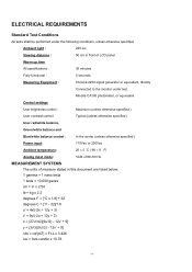
... CA100 photometer, or equivalent Control settings User brightness control : Maximum (unless otherwise specified ) User contrast control: Typical (unless otherwise specified ) User red/white balance, Green/white balance and Blue/white balance control : In the center (unless otherwise specified ) Power input: 110Vac or 230Vac Ambient temperature: 20 ± 5 ˚C ( 68 ± 9 ˚ F) Analog input mode: 1024 x768 /60 Hz MEASUREMENT SYSTEMS The units of LCD panel Warrn up time All specifications : 30 minutes Fully functional...
... CA100 photometer, or equivalent Control settings User brightness control : Maximum (unless otherwise specified ) User contrast control: Typical (unless otherwise specified ) User red/white balance, Green/white balance and Blue/white balance control : In the center (unless otherwise specified ) Power input: 110Vac or 230Vac Ambient temperature: 20 ± 5 ˚C ( 68 ± 9 ˚ F) Analog input mode: 1024 x768 /60 Hz MEASUREMENT SYSTEMS The units of LCD panel Warrn up time All specifications : 30 minutes Fully functional...

AL1515 LCD Monitor Service Guide
Page 10
... × 768 (60/70/75 Hz) 1).Video: RGB analog 0.7V peak to peak Sync: TTL positive or negative Signal connector: 15 pin Mini D type, (standard VGA video) 3.5 mm stereo audio jack (Audio) (For AL1515 m only) Audio power: 0.5Wrms + 0.5Wrms (300Hz - 10kHz (S.P.L. - 10 dB))(AL1515 m only) Front control: power on/off with LED select adjustment (+,-) Interface frequency Horizontal Frequency 24KHz --61KHz Vertical Frequency 56Hz ------75Hz Plug & play: Support VESA DDC2B functions Power Input voltage: Single phase, 50/60HZ, 100 VAC...
... × 768 (60/70/75 Hz) 1).Video: RGB analog 0.7V peak to peak Sync: TTL positive or negative Signal connector: 15 pin Mini D type, (standard VGA video) 3.5 mm stereo audio jack (Audio) (For AL1515 m only) Audio power: 0.5Wrms + 0.5Wrms (300Hz - 10kHz (S.P.L. - 10 dB))(AL1515 m only) Front control: power on/off with LED select adjustment (+,-) Interface frequency Horizontal Frequency 24KHz --61KHz Vertical Frequency 56Hz ------75Hz Plug & play: Support VESA DDC2B functions Power Input voltage: Single phase, 50/60HZ, 100 VAC...
AL1515 LCD Monitor Service Guide
Page 11
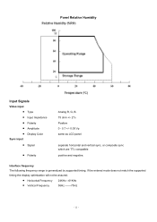
... match the supported timing the display optimization will not be assured. • Horizontal Frequency • Vertical Frequency 24KHz --61KHz 56Hz -------75Hz - 11 - Panel Relative Humidity Input Signals Video input • Type • Input Impedance • Polarity • Amplitude • Display Color Sync input • Signal • Polarity Analog R, G, B. 75 ohm +/- 2% Positive 0 - 0.7 +/- 0.05 Vp same as LCD panel separate horizontal and vertical sync, or composite sync which are TTL compatible positive and negative. Interface frequency The following frequency range is...
... match the supported timing the display optimization will not be assured. • Horizontal Frequency • Vertical Frequency 24KHz --61KHz 56Hz -------75Hz - 11 - Panel Relative Humidity Input Signals Video input • Type • Input Impedance • Polarity • Amplitude • Display Color Sync input • Signal • Polarity Analog R, G, B. 75 ohm +/- 2% Positive 0 - 0.7 +/- 0.05 Vp same as LCD panel separate horizontal and vertical sync, or composite sync which are TTL compatible positive and negative. Interface frequency The following frequency range is...
AL1515 LCD Monitor Service Guide
Page 18
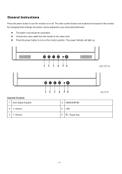
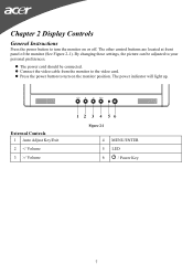
AL1515 m External Controls 1 Auto Adjust Key/Exit 2 / Volume 4 MENU/ENTER 5 LED 6 / Power Key AL1515 - 18 - Connect the video cable from the monitor to turn the monitor on the monitor position. The power indicator will light up. By changing these settings, the picture can be connected. The other control buttons are located at front panel of the monitor. General Instructions Press the power button to turn on or off. The power cord should be adjusted to your personal preferences. Press the power button to the video card.
AL1515 m External Controls 1 Auto Adjust Key/Exit 2 / Volume 4 MENU/ENTER 5 LED 6 / Power Key AL1515 - 18 - Connect the video cable from the monitor to turn the monitor on the monitor position. The power indicator will light up. By changing these settings, the picture can be connected. The other control buttons are located at front panel of the monitor. General Instructions Press the power button to turn on or off. The power cord should be adjusted to your personal preferences. Press the power button to the video card.
AL1515 LCD Monitor Service Guide
Page 29
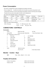
... to any power saving state to another can be instantaneous. Mode H-Sync. Assignment of 15-pin D-sub: 1 Red Video 9 +5V FOR DDC 2 Green Video 10 Detect 3 Blue Video 11 Serial Data for ISP 4 Serial Clock for ISP 12 Serial Data for DDC 5 Ground 13 H-Sync. 6 Red Ground 14 V-Sync. 7 Green Ground 15 Serial Clock for PC : 3.5mm Stereo female Monitor Control Keys KEY : Power , Menu , Adjust +/- , Vol +/-, Auto Position Of Controls Position of all switches Position of LED : Bottom side...
... to any power saving state to another can be instantaneous. Mode H-Sync. Assignment of 15-pin D-sub: 1 Red Video 9 +5V FOR DDC 2 Green Video 10 Detect 3 Blue Video 11 Serial Data for ISP 4 Serial Clock for ISP 12 Serial Data for DDC 5 Ground 13 H-Sync. 6 Red Ground 14 V-Sync. 7 Green Ground 15 Serial Clock for PC : 3.5mm Stereo female Monitor Control Keys KEY : Power , Menu , Adjust +/- , Vol +/-, Auto Position Of Controls Position of all switches Position of LED : Bottom side...
AL1515 LCD Monitor Service Guide
Page 32
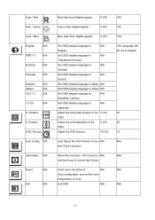
User / Red User / Green User / Blue English N/A 繁體中文 N/A Deutsch N/A Français N/A Español N/A Italiano N/A 简体中文 N/A 日本語 N/A H. Set OSD display language to Spain. Adjust the horizontal position of the 0-100 OSD. Adjust the verticalposition of the 0-100 OSD. Set OSD display language to N/A German. N/A Set OSD display language to N/A Japanese. Set OSD display language to N/A Simplified Chinese. Show the resolution, H/V frequency N/A and input port of picture. Set ...
User / Red User / Green User / Blue English N/A 繁體中文 N/A Deutsch N/A Français N/A Español N/A Italiano N/A 简体中文 N/A 日本語 N/A H. Set OSD display language to Spain. Adjust the horizontal position of the 0-100 OSD. Adjust the verticalposition of the 0-100 OSD. Set OSD display language to N/A German. N/A Set OSD display language to N/A Japanese. Set OSD display language to N/A Simplified Chinese. Show the resolution, H/V frequency N/A and input port of picture. Set ...
AL1515 LCD Monitor Service Guide
Page 33
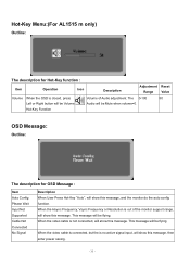
... Description Adjustment Reset Range Value Volume When the OSD is no active signal input, will show this message, then enter power saving. - 33 - Hot-Key Menu:(For AL1515 m only) Outline: The description for OSD Message : Item Auto Config Please Wait Input Not Supported Cable Not Connected No Signal Description When User Press Hot-Key "Auto", will show this message, and the monitor do the auto config function. When the Hsync Frequency, Vsync Frequency or Resolution...
... Description Adjustment Reset Range Value Volume When the OSD is no active signal input, will show this message, then enter power saving. - 33 - Hot-Key Menu:(For AL1515 m only) Outline: The description for OSD Message : Item Auto Config Please Wait Input Not Supported Cable Not Connected No Signal Description When User Press Hot-Key "Auto", will show this message, and the monitor do the auto config function. When the Hsync Frequency, Vsync Frequency or Resolution...
AL1515 LCD Monitor Service Guide
Page 35
... MUST BE A VIDEO INPUT SIGNAL. This reduces the monitor's internal power supply consumption. The voltage rating for connection to use a cord set by the Video Electronics Standards Association(VESA) and/or the United States Environmental Protection Agency (EPA) and The Swedish Confederation Employees (NUTEK). THIS MONITOR WILL APPEAR TO BE NON-FUNCTIONAL IF THERE IS NO VIDEO INPUT SIGNAL. When there is no video-input signal present. Plug and play Plug & play...
... MUST BE A VIDEO INPUT SIGNAL. This reduces the monitor's internal power supply consumption. The voltage rating for connection to use a cord set by the Video Electronics Standards Association(VESA) and/or the United States Environmental Protection Agency (EPA) and The Swedish Confederation Employees (NUTEK). THIS MONITOR WILL APPEAR TO BE NON-FUNCTIONAL IF THERE IS NO VIDEO INPUT SIGNAL. When there is no video-input signal present. Plug and play Plug & play...
AL1515 User's Guide
Page 1
... Safety Instructions ...3 Chapter 1 Installation ...4 Unpacking...4 Connecting the LCD Monitor and Base 4 Viewing Angle Adjustment...4 Detaching LCD Monitor from Its Stand 5 Interface for Arm Applications ...5 Connecting the Display ...5 Connecting the AC Power...5 Connecting the Audio Cable (For AL1515 m and AL1515 bm 6 Power Management System ...6 Chapter 2 Display Controls 7 General Instructions ...7 Front Panel Control...8 How To Adjust A Setting...9 Adjusting The Picture ...9 Chapter 3 Technical Information 11 Specifications...11 Standard Timing Table...13 Troubleshooting ...15...
... Safety Instructions ...3 Chapter 1 Installation ...4 Unpacking...4 Connecting the LCD Monitor and Base 4 Viewing Angle Adjustment...4 Detaching LCD Monitor from Its Stand 5 Interface for Arm Applications ...5 Connecting the Display ...5 Connecting the AC Power...5 Connecting the Audio Cable (For AL1515 m and AL1515 bm 6 Power Management System ...6 Chapter 2 Display Controls 7 General Instructions ...7 Front Panel Control...8 How To Adjust A Setting...9 Adjusting The Picture ...9 Chapter 3 Technical Information 11 Specifications...11 Standard Timing Table...13 Troubleshooting ...15...
AL1515 User's Guide
Page 5
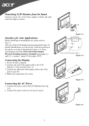
... Arm Applications Before installing to mounting device, please refer to the LCD Monitor.(See Fig. 1-6) 2. Connect the power cord to Fig.1-3. Connecting the Display 1. Power off your PC. 4. The rear of the signal cable to the VGA port on your computer. 2. Connect the other end of the signal cable to the LCD Monitor's VGA port.(See Fig 1-5) 3. Connecting the AC Power 1. Connect the power cord to release. Detaching LCD Monitor from Its Stand Unscrew screws the swivel base support column and pull...
... Arm Applications Before installing to mounting device, please refer to the LCD Monitor.(See Fig. 1-6) 2. Connect the power cord to Fig.1-3. Connecting the Display 1. Power off your PC. 4. The rear of the signal cable to the VGA port on your computer. 2. Connect the other end of the signal cable to the LCD Monitor's VGA port.(See Fig 1-5) 3. Connecting the AC Power 1. Connect the power cord to release. Detaching LCD Monitor from Its Stand Unscrew screws the swivel base support column and pull...
AL1515 User's Guide
Page 7
Chapter 2 Display Controls General Instructions Press the power button to turn on or off. The other control buttons are located at front panel of the monitor (See Figure 2-1). Connect the video cable from the monitor to turn the monitor on the monitor position. External Controls 1 Auto Adjust Key/Exit 2 / Volume Figure 2-1 4 MENU/ENTER 5 LED 6 / Power Key 7 By changing these settings, the picture can be connected. The power cord should be adjusted to your personal preferences. The power indicator will light up. Press the power button to the video card.
Chapter 2 Display Controls General Instructions Press the power button to turn on or off. The other control buttons are located at front panel of the monitor (See Figure 2-1). Connect the video cable from the monitor to turn the monitor on the monitor position. External Controls 1 Auto Adjust Key/Exit 2 / Volume Figure 2-1 4 MENU/ENTER 5 LED 6 / Power Key 7 By changing these settings, the picture can be connected. The power cord should be adjusted to your personal preferences. The power indicator will light up. Press the power button to the video card.

AL1515 User's Guide
Page 8
... keep the monitor looking new, periodically clean it . 8 Front Panel Control /Power Button: Press this button for Audio model) or navigate through adjustment icons when OSD is ON or adjust a function when function is activated. The Auto Adjustment function is ON or Exit OSD menu when in handy if you ever have to turn the monitor ON or OFF, And display the monitor's state. Orange - When OSD menu is in off mode MENU / ENTER : Activate OSD menu...
... keep the monitor looking new, periodically clean it . 8 Front Panel Control /Power Button: Press this button for Audio model) or navigate through adjustment icons when OSD is ON or adjust a function when function is activated. The Auto Adjustment function is ON or Exit OSD menu when in handy if you ever have to turn the monitor ON or OFF, And display the monitor's state. Orange - When OSD menu is in off mode MENU / ENTER : Activate OSD menu...
AL1515 User's Guide
Page 9
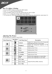
... screen image. Adjusts the background brightness of the current function. 5. To exit and save, select the exit function. Set the color temperature to select the desired function. 3. How To Adjust A Setting 1. User / Green Adjusts Red/Green/Blue intensity. Press < or > to cool white. Position N/A Warm N/A Cool User / Red Adjust picture Clock Set the color temperature to activate the OSD window. 2. Press the MENU-button to warm white. Adjusting The Picture The descriptions for function control LEDS Main Menu Icon Sub Menu Icon Sub Menu Item Contrast Brightness...
... screen image. Adjusts the background brightness of the current function. 5. To exit and save, select the exit function. Set the color temperature to select the desired function. 3. How To Adjust A Setting 1. User / Green Adjusts Red/Green/Blue intensity. Press < or > to cool white. Position N/A Warm N/A Cool User / Red Adjust picture Clock Set the color temperature to activate the OSD window. 2. Press the MENU-button to warm white. Adjusting The Picture The descriptions for function control LEDS Main Menu Icon Sub Menu Icon Sub Menu Item Contrast Brightness...
AL1515 User's Guide
Page 10
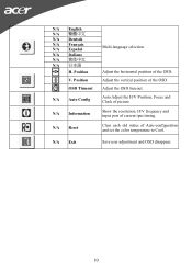
...-language selection. N/A English N/A N/A Deutsch N/A Français N/A Español N/A Italiano N/A N/A 日本語 H. Adjust the horizontal position of picture. N/A Auto Config Auto Adjust the H/V Position, Focus and Clock of the OSD. N/A Information Show the resolution, H/V frequency and input port of the OSD. Position Adjust the vertical position of current iput timing. N/A Reset Clear each old status of Auto-configuration and set the color temperature to Cool. V. N/A Exit Save user adjustment and OSD disappear. 10 OSD Timeout Adjust the OSD...
...-language selection. N/A English N/A N/A Deutsch N/A Français N/A Español N/A Italiano N/A N/A 日本語 H. Adjust the horizontal position of picture. N/A Auto Config Auto Adjust the H/V Position, Focus and Clock of the OSD. N/A Information Show the resolution, H/V frequency and input port of the OSD. Position Adjust the vertical position of current iput timing. N/A Reset Clear each old status of Auto-configuration and set the color temperature to Cool. V. N/A Exit Save user adjustment and OSD disappear. 10 OSD Timeout Adjust the OSD...
AL1515 User's Guide
Page 11
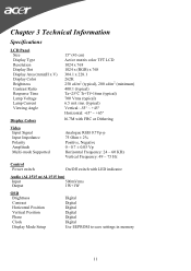
...+45° Horizontal: -65° ~ +65° Display Colors 16.7M with FRC or Dithering Video Input Signal Input Impedance Polarity Amplitude Multi-mode Supported Analogue RGB 0.7Vp-p 75 Ohm ± 2% Positive, Negative 0 - 0.7 ± 0.05 Vp Horizontal Frequency: 24 ~ 60 KHz Vertical Frequency: 49 ~ 75 Hz Control Power switch On/Off switch with LED indicator Audio (AL1515 m/AL1515 bm) Input 500mVrms Output 1W+1W OSD Brightness Contrast Horizontal Position Vertical Position Phase Clock Display Mode Setup Digital Digital Digital Digital Digital Digital Use EEPROM to save settings in...
...+45° Horizontal: -65° ~ +65° Display Colors 16.7M with FRC or Dithering Video Input Signal Input Impedance Polarity Amplitude Multi-mode Supported Analogue RGB 0.7Vp-p 75 Ohm ± 2% Positive, Negative 0 - 0.7 ± 0.05 Vp Horizontal Frequency: 24 ~ 60 KHz Vertical Frequency: 49 ~ 75 Hz Control Power switch On/Off switch with LED indicator Audio (AL1515 m/AL1515 bm) Input 500mVrms Output 1W+1W OSD Brightness Contrast Horizontal Position Vertical Position Phase Clock Display Mode Setup Digital Digital Digital Digital Digital Digital Use EEPROM to save settings in...
AL1515 User's Guide
Page 12
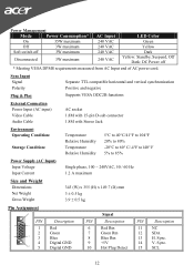
Sync Input Signal Polarity Plug & Play Separate TTL compatible horizontal and vertical synchronization Positive and negative Supports VESA DDC2B functions External Connection Power Input (AC input) Video Cable Audio Cable AC socket 1.8M with 15-pin D-sub connector 1.8M with Stereo Jack Environment Operating Condition: Storage Condition: Temperature Relative Humidity Temperature Relative Humidity 5°C to 40°C/41°F to 104°F 20% ...
Sync Input Signal Polarity Plug & Play Separate TTL compatible horizontal and vertical synchronization Positive and negative Supports VESA DDC2B functions External Connection Power Input (AC input) Video Cable Audio Cable AC socket 1.8M with 15-pin D-sub connector 1.8M with Stereo Jack Environment Operating Condition: Storage Condition: Temperature Relative Humidity Temperature Relative Humidity 5°C to 40°C/41°F to 104°F 20% ...
AL1515 User's Guide
Page 15
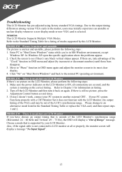
... LCD Monitor, the output timing of Range" message. Please change to an alternative mode listed in OSD menu again and adjust the monitor screen to LCD monitor at all connections are , take advantage of modes supported by increment or decrement numbers) until those bars disappear. 3. Also, if the signal cable is selected. Troubleshooting This LCD Monitor has pre-adjusted using factory standard VGA timings. In Windows XP open the specific application where the problems appear. 2. Move to another external CRT. Make...
... LCD Monitor, the output timing of Range" message. Please change to an alternative mode listed in OSD menu again and adjust the monitor screen to LCD monitor at all connections are , take advantage of modes supported by increment or decrement numbers) until those bars disappear. 3. Also, if the signal cable is selected. Troubleshooting This LCD Monitor has pre-adjusted using factory standard VGA timings. In Windows XP open the specific application where the problems appear. 2. Move to another external CRT. Make...


