User Manual
Page 3
Installation 12 Pre-installation Precautions 12 2.1 CPU Installation 13 2.2 Installation of CPU Fan and Heatsink 13 2.3 Installation of Memory Modules (DIMM 14 2.4 Expansion Slots (PCI, HDMR, and PCI Express Slots) .. 15 2.5 ...Serial ATA (SATA) / Serial ATAII (SATAII) Hard Disks Installation 22 2.9 Hot Plug and Hot Swap Functions for Windows® VistaTM Basic Logo 9 1.4 Motherboard Layout 10 1.5 ASRock 6CH I/O Plus 11 TM 2. BIOS SETUP UTILITY 28 3.1 Introduction 28 3.1.1 BIOS Menu Bar 28 3.1.2 Navigation Keys 29 3.2 Main Screen 29 3 Introduction 5 1.1 Package Contents 5...
Installation 12 Pre-installation Precautions 12 2.1 CPU Installation 13 2.2 Installation of CPU Fan and Heatsink 13 2.3 Installation of Memory Modules (DIMM 14 2.4 Expansion Slots (PCI, HDMR, and PCI Express Slots) .. 15 2.5 ...Serial ATA (SATA) / Serial ATAII (SATAII) Hard Disks Installation 22 2.9 Hot Plug and Hot Swap Functions for Windows® VistaTM Basic Logo 9 1.4 Motherboard Layout 10 1.5 ASRock 6CH I/O Plus 11 TM 2. BIOS SETUP UTILITY 28 3.1 Introduction 28 3.1.1 BIOS Menu Bar 28 3.1.2 Navigation Keys 29 3.2 Main Screen 29 3 Introduction 5 1.1 Package Contents 5...
User Manual
Page 4
3.3 Advanced Screen 30 3.3.1 CPU Configuration 30 3.3.2 Chipset Configuration 32 3.3.3 ACPI Configuration 35 3.3.4 IDE Configuration 36 3.3.5 PCIPnP Configuration 38 3.3.6 Floppy Configuration 38 3.3.7 Super IO Configuration 39 3.3.8 USB Configuration 40 3.4 Hardware ...
3.3 Advanced Screen 30 3.3.1 CPU Configuration 30 3.3.2 Chipset Configuration 32 3.3.3 ACPI Configuration 35 3.3.4 IDE Configuration 36 3.3.5 PCIPnP Configuration 38 3.3.6 Floppy Configuration 38 3.3.7 Super IO Configuration 39 3.3.8 USB Configuration 40 3.4 Hardware ...
User Manual
Page 5
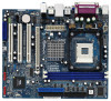
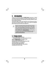
...configuration guide to change without further notice. www.asrock.com/support/index.asp 1.1 Package Contents ASRock P4VM900-SATA2 Motherboard (Micro ATX Form Factor: 9.6-in x 8.0-in, 24.4 cm x 20.3 cm) ASRock P4VM900-SATA2 Quick Installation Guide ASRock P4VM900-SATA2 Support CD One 80-conductor Ultra ATA 66... HDD Power Cable (Optional) One ASRock 6CH I/O PlusTM Shield 5 You may find the latest VGA cards and CPU support lists on ASRock website without notice. It delivers excellent performance with robust design conforming to ASRock's commitment to quality and endurance. Introduction...
...configuration guide to change without further notice. www.asrock.com/support/index.asp 1.1 Package Contents ASRock P4VM900-SATA2 Motherboard (Micro ATX Form Factor: 9.6-in x 8.0-in, 24.4 cm x 20.3 cm) ASRock P4VM900-SATA2 Quick Installation Guide ASRock P4VM900-SATA2 Support CD One 80-conductor Ultra ATA 66... HDD Power Cable (Optional) One ASRock 6CH I/O PlusTM Shield 5 You may find the latest VGA cards and CPU support lists on ASRock website without notice. It delivers excellent performance with robust design conforming to ASRock's commitment to quality and endurance. Introduction...
User Manual
Page 6
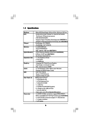
... - 1 x VGA Port - 1 x Parallel Port (ECP/EPP Support) - 6 x Ready-to-Use USB 2.0 Ports - 1 x RJ-45 LAN Port - Pixel Shader 2.0, DirectX 9.0 VGA - Supports Wake-On-LAN ASRock 6CH I /O Connector - CPU Frequency Stepless Control (see CAUTION 1) - VIA® PHY VT6103 - Socket 478 for Intel® Pentium® 4 / Celeron® D (Prescott, Northwood, Willamate) processors - Northbridge: VIA...
... - 1 x VGA Port - 1 x Parallel Port (ECP/EPP Support) - 6 x Ready-to-Use USB 2.0 Ports - 1 x RJ-45 LAN Port - Pixel Shader 2.0, DirectX 9.0 VGA - Supports Wake-On-LAN ASRock 6CH I /O Connector - CPU Frequency Stepless Control (see CAUTION 1) - VIA® PHY VT6103 - Socket 478 for Intel® Pentium® 4 / Celeron® D (Prescott, Northwood, Willamate) processors - Northbridge: VIA...
User Manual
Page 7
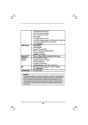
... Monitor OS Certifications - Supports "Plug and Play" - ACPI 1.1 Compliance Wake Up Events - Drivers, Utilities, AntiVirus Software (Trial Version) - CPU Temperature Sensing - FCC, CE, WHQL WARNING Please realize that there is a certain risk involved with USB45 ports on the I/O panel) (see ...USB 2.0 headers (support 4 USB 2.0 ports; 2 of your own risk and expense. CPU Fan Tachometer - Voltage Monitoring: +12V, +5V, +3.3V, Vcore - It should be done at your system. AMI Legal BIOS - CPU/Chassis FAN connector - 20 pin ATX power connector - 4 pin 12V power connector - Supports...
... Monitor OS Certifications - Supports "Plug and Play" - ACPI 1.1 Compliance Wake Up Events - Drivers, Utilities, AntiVirus Software (Trial Version) - CPU Temperature Sensing - FCC, CE, WHQL WARNING Please realize that there is a certain risk involved with USB45 ports on the I/O panel) (see ...USB 2.0 headers (support 4 USB 2.0 ports; 2 of your own risk and expense. CPU Fan Tachometer - Voltage Monitoring: +12V, +5V, +3.3V, Vcore - It should be done at your system. AMI Legal BIOS - CPU/Chassis FAN connector - 20 pin ATX power connector - 4 pin 12V power connector - Supports...
User Manual
Page 8
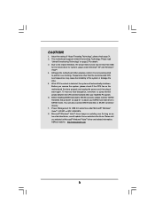
... latest driver, we will automatically shutdown. Frequencies other than the recommended CPU bus frequencies may be less than 4GB for the reservation for details. 3. Due to our website in the future. ASRock website http://www.asrock.com 8 To improve heat dissipation, remember to SATAII connector directly. ...7. You can also connect SATA hard disk to spray thermal grease between the CPU and the heatsink when you resume the system, please...
... latest driver, we will automatically shutdown. Frequencies other than the recommended CPU bus frequencies may be less than 4GB for the reservation for details. 3. Due to our website in the future. ASRock website http://www.asrock.com 8 To improve heat dissipation, remember to SATAII connector directly. ...7. You can also connect SATA hard disk to spray thermal grease between the CPU and the heatsink when you resume the system, please...
User Manual
Page 9
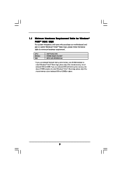
... system integrators and users who purchase our motherboard and plan to 128MB or above. 9 1.3 Minimum Hardware Requirement Table for minimum hardware requirement. CPU Memory VGA Intel® 1GHz CPU 512MB Single Channel* DX9.0 with WDDM Driver * If you use onboard VGA with total system memory size above 512MB and plan to submit...
... system integrators and users who purchase our motherboard and plan to 128MB or above. 9 1.3 Minimum Hardware Requirement Table for minimum hardware requirement. CPU Memory VGA Intel® 1GHz CPU 512MB Single Channel* DX9.0 with WDDM Driver * If you use onboard VGA with total system memory size above 512MB and plan to submit...
User Manual
Page 10
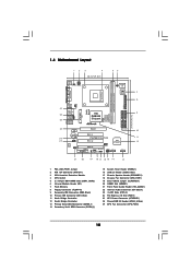
...EXPRESS FSB800 DDR400 1 Top: Line In Center: Line Out Bottom: Mic In 24 23 22 PCIE1 LAN PHY IDE1 IDE2 CMOS Battery CD1 PCI 1 P4VM900-SATA2 PCI 2 VIA VT8237S Audio CODEC 1 HD_AUDIO1 PCI 3 USB2.0 CHA_FAN1 CLRCMOS1 HDMR1 5.1CH HD 1 ATA133 1 SPEAKER1 USB67 PANEL 1 PLED PWRBTN 1... HDLED RESET SATAII_2 SATAII_1 10 11 12 21 20 19 18 17 16 15 14 13 1 PS2_USB_PWR1 Jumper 2 ATX 12V Connector (ATX12V1) 3 CPU Heatsink Retention Module 4 CPU Socket 5 2 x 184-pin DDR DIMM Slots (DDR1, DDR2) 6 Infrared Module Header (IR1) 7 Flash Memory 8 Floppy Connector (FLOPPY1) 9 Secondary...
...EXPRESS FSB800 DDR400 1 Top: Line In Center: Line Out Bottom: Mic In 24 23 22 PCIE1 LAN PHY IDE1 IDE2 CMOS Battery CD1 PCI 1 P4VM900-SATA2 PCI 2 VIA VT8237S Audio CODEC 1 HD_AUDIO1 PCI 3 USB2.0 CHA_FAN1 CLRCMOS1 HDMR1 5.1CH HD 1 ATA133 1 SPEAKER1 USB67 PANEL 1 PLED PWRBTN 1... HDLED RESET SATAII_2 SATAII_1 10 11 12 21 20 19 18 17 16 15 14 13 1 PS2_USB_PWR1 Jumper 2 ATX 12V Connector (ATX12V1) 3 CPU Heatsink Retention Module 4 CPU Socket 5 2 x 184-pin DDR DIMM Slots (DDR1, DDR2) 6 Infrared Module Header (IR1) 7 Flash Memory 8 Floppy Connector (FLOPPY1) 9 Secondary...
User Manual
Page 13
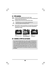
... to dissipate heat. Lift Lever Up to 90° STEP 1: Lift The Socket Lever Up to 90° CPU Marked Corner Socket Marked Corner STEP 2/STEP 3: Match The CPU Marked Corner to indicate that it is in place, press it fits in one correct orientation. For proper installation,... please kindly refer to secure the CPU. 2.1 CPU Installation Step 1. Step 4. The lever clicks on the socket while you push down the socket lever to the instruction manuals of the socket...
... to dissipate heat. Lift Lever Up to 90° STEP 1: Lift The Socket Lever Up to 90° CPU Marked Corner Socket Marked Corner STEP 2/STEP 3: Match The CPU Marked Corner to indicate that it is in place, press it fits in one correct orientation. For proper installation,... please kindly refer to secure the CPU. 2.1 CPU Installation Step 1. Step 4. The lever clicks on the socket while you push down the socket lever to the instruction manuals of the socket...
User Manual
Page 19
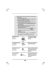
...below: A. If you use AC'97 audio panel, please install it to [Enabled]. Chassis Fan Connector (3-pin CHA_FAN1) (see p.10, No. 18) CPU Fan Connector (3-pin CPU_FAN1) (see p.10, No. 17) PLED+ PLEDPWRBTN# GND 1 DUMMY RESET# GND HDLEDHDLED+ 1 SPEAKER DUMMY DUMMY +5V This... header accommodates several system front panel functions. B. Please connect the CPU fan cable to this connector and match the black wire to the ground pin. 19 Enter Advanced Settings, and then select Chipset Configuration. 2. For...
...below: A. If you use AC'97 audio panel, please install it to [Enabled]. Chassis Fan Connector (3-pin CHA_FAN1) (see p.10, No. 18) CPU Fan Connector (3-pin CPU_FAN1) (see p.10, No. 17) PLED+ PLEDPWRBTN# GND 1 DUMMY RESET# GND HDLEDHDLED+ 1 SPEAKER DUMMY DUMMY +5V This... header accommodates several system front panel functions. B. Please connect the CPU fan cable to this connector and match the black wire to the ground pin. 19 Enter Advanced Settings, and then select Chipset Configuration. 2. For...
User Manual
Page 20
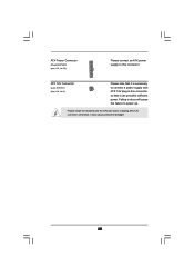
ATX Power Connector (20-pin ATXPWR1) (see p.10, No. 2) Please note that it may cause permanent damage! 20 ATX 12V Connector (4-pin ATX12V1) (see p.10, No. 25) Please connect an ATX power supply to this connector so that it is necessary to connect a power supply with ATX 12V plug to this connector. Failing to do so will cause the failure to power up. otherwise, it can provides sufficient power. Please install the heatsink and the CPU fan before installing ATX 12V connector;
ATX Power Connector (20-pin ATXPWR1) (see p.10, No. 2) Please note that it may cause permanent damage! 20 ATX 12V Connector (4-pin ATX12V1) (see p.10, No. 25) Please connect an ATX power supply to this connector so that it is necessary to connect a power supply with ATX 12V plug to this connector. Failing to do so will cause the failure to power up. otherwise, it can provides sufficient power. Please install the heatsink and the CPU fan before installing ATX 12V connector;
User Manual
Page 27
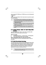
...174; VistaTM on IDE HDDs and want to manage (create, convert, delete or rebuild) RAID functions on SATA / SATAII HDDs, please set "CPU Host Frequency" option of BIOS setup to [Auto], which means during overclocking, but PCI / PCIE bus is untied during overclocking, FSB enjoys better... margin due to the warning on your system. After setting up BIOS. If you apply Untied Overclocking Technology. 27 Therefore, CPU FSB is in the Support CD: .. \ RAID Installation Guide 2. If you want to install Windows® 2000 / XP / VistaTM OS on...
...174; VistaTM on IDE HDDs and want to manage (create, convert, delete or rebuild) RAID functions on SATA / SATAII HDDs, please set "CPU Host Frequency" option of BIOS setup to [Auto], which means during overclocking, but PCI / PCIE bus is untied during overclocking, FSB enjoys better... margin due to the warning on your system. After setting up BIOS. If you apply Untied Overclocking Technology. 27 Therefore, CPU FSB is in the Support CD: .. \ RAID Installation Guide 2. If you want to install Windows® 2000 / XP / VistaTM OS on...
User Manual
Page 29
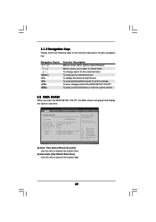
... UTILITY Main Advanced H/W Monitor Boot Security Exit System Overview System Time System Date [16:15:31] [Mon 08/20/2007] BIOS Version : P4VM900-SATA2 BIOS P1.00 Processor Type : Intel (R) CPU 2.80GHz Processor Speed : 2800MHz Microcode Update : F34/17 Cache Size : 256KB Total Memory DDR1 DDR2 : 1024MB with 128MB shared memory : 512MB/166MHz...
... UTILITY Main Advanced H/W Monitor Boot Security Exit System Overview System Time System Date [16:15:31] [Mon 08/20/2007] BIOS Version : P4VM900-SATA2 BIOS P1.00 Processor Type : Intel (R) CPU 2.80GHz Processor Speed : 2800MHz Microcode Update : F34/17 Cache Size : 256KB Total Memory DDR1 DDR2 : 1024MB with 128MB shared memory : 512MB/166MHz...
User Manual
Page 30
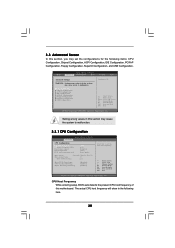
...] Ratio Status Ratio Actual Value Unlocked (Max:21, Min:14) 21 Ratio CMOS Setting [21] Max CPUID Value Limit CPU Thermal Throttling Hyper Threading Technology [Disabled] [Enabled] [Enabled] Select how to Sub Screen F1 General Help F9 Load Defaults F10...Settings WARNING : Setting wrong values in this motherboard. Setting wrong values in below sections may cause system to malfunction. 3.3.1 CPU Configuration BIOS SETUP UTILITY Advanced CPU Configuration CPU Host Frequency Actual Frequency (MHz) Boot Failure Guard Spread Spectrum PCIE clock operation mode [Auto] [133] [Enabled] ...
...] Ratio Status Ratio Actual Value Unlocked (Max:21, Min:14) 21 Ratio CMOS Setting [21] Max CPUID Value Limit CPU Thermal Throttling Hyper Threading Technology [Disabled] [Enabled] [Enabled] Select how to Sub Screen F1 General Help F9 Load Defaults F10...Settings WARNING : Setting wrong values in this motherboard. Setting wrong values in below sections may cause system to malfunction. 3.3.1 CPU Configuration BIOS SETUP UTILITY Advanced CPU Configuration CPU Host Frequency Actual Frequency (MHz) Boot Failure Guard Spread Spectrum PCIE clock operation mode [Auto] [133] [Enabled] ...
User Manual
Page 31
...® 4 processor that supports Hyper-Threading technology and an operating system that cannot support CPUs with disable. Hyper Threading Technology To enable this CPU. The default value is [Auto]. Ratio Actual Value This is "Locked" or "Unlocked". NT4.0) cannot handle the function with extended CPUID ...Ratio Status This is a read -only item, which displays whether the ratio status of Boot Failure Guard. Max CPUID Value Limit For Prescott CPU only, some OSes (ex. Boot Failure Guard Enable or disable the feature of this option is [Sync. mode]. If it shows "Locked...
...® 4 processor that supports Hyper-Threading technology and an operating system that cannot support CPUs with disable. Hyper Threading Technology To enable this CPU. The default value is [Auto]. Ratio Actual Value This is "Locked" or "Unlocked". NT4.0) cannot handle the function with extended CPUID ...Ratio Status This is a read -only item, which displays whether the ratio status of Boot Failure Guard. Max CPUID Value Limit For Prescott CPU only, some OSes (ex. Boot Failure Guard Enable or disable the feature of this option is [Sync. mode]. If it shows "Locked...
User Manual
Page 41
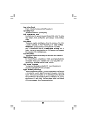
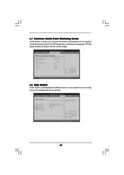
... Device Hard Disk Drives Removable Drives [1st Floppy Device] [HDD: PM - BIOS SETUP UTILITY Main Advanced H/W Monitor Boot Security Exit Hardware Health Event Monitoring CPU Temperature M / B Temperature CPU Fan Speed Chassis Fan Speed Vcore + 3.30V + 5.00V + 12.00V : 37 C / 98 F : 31 C / 87 F : 2463 RPM : N/A : 1....41 3.4 Hardware Health Event Monitoring Screen In this section, it allows you to monitor the status of the CPU temperature, motherboard temperature, CPU fan speed, chassis fan speed, and the critical voltage. MAXTOR 6L08] [CD / DVD] [USB] Configure Settings during System...
... Device Hard Disk Drives Removable Drives [1st Floppy Device] [HDD: PM - BIOS SETUP UTILITY Main Advanced H/W Monitor Boot Security Exit Hardware Health Event Monitoring CPU Temperature M / B Temperature CPU Fan Speed Chassis Fan Speed Vcore + 3.30V + 5.00V + 12.00V : 37 C / 98 F : 31 C / 87 F : 2463 RPM : N/A : 1....41 3.4 Hardware Health Event Monitoring Screen In this section, it allows you to monitor the status of the CPU temperature, motherboard temperature, CPU fan speed, chassis fan speed, and the critical voltage. MAXTOR 6L08] [CD / DVD] [USB] Configure Settings during System...
Quick Installation Guide
Page 2
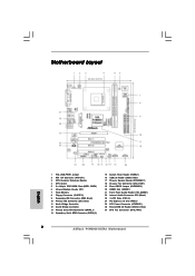
Motherboard Layout English 1 PS2_USB_PWR1 Jumper 2 ATX 12V Connector (ATX12V1) 3 CPU Heatsink Retention Module 4 CPU Socket 5 2 x 184-pin DDR DIMM Slots (DDR1, DDR2) 6 Infrared Module Header (IR1) 7 Flash Memory 8 Floppy Connector (FLOPPY1) 9 Secondary IDE Connector (IDE2, Black) 10 Primary IDE ... Connector: CD1 (Black) 23 3 x PCI Slots (PCI1- 3) 24 PCI Express x16 Slot (PCIE1) 25 ATX Power Connector (ATXPWR1) 26 Shared USB 2.0 Header (USB4_5, Blue) 27 CPU Fan Connector (CPU_FAN1) 2 ASRock P4VM900-SATA2 Motherboard
Motherboard Layout English 1 PS2_USB_PWR1 Jumper 2 ATX 12V Connector (ATX12V1) 3 CPU Heatsink Retention Module 4 CPU Socket 5 2 x 184-pin DDR DIMM Slots (DDR1, DDR2) 6 Infrared Module Header (IR1) 7 Flash Memory 8 Floppy Connector (FLOPPY1) 9 Secondary IDE Connector (IDE2, Black) 10 Primary IDE ... Connector: CD1 (Black) 23 3 x PCI Slots (PCI1- 3) 24 PCI Express x16 Slot (PCIE1) 25 ATX Power Connector (ATXPWR1) 26 Shared USB 2.0 Header (USB4_5, Blue) 27 CPU Fan Connector (CPU_FAN1) 2 ASRock P4VM900-SATA2 Motherboard

Quick Installation Guide
Page 4
... find the latest VGA cards and CPU support lists on ASRock website without notice. In case any modifications of the motherboard and step-bystep installation guide. www.asrock.com/support/index.asp 1.1 Package Contents ASRock P4VM900-SATA2 Motherboard (Micro ATX Form Factor: 9.6-in x 8.0-in, 24.4 cm x 20.3 cm) ASRock P4VM900-SATA2 Quick Installation Guide ASRock P4VM900-SATA2 Support CD One 80-conductor...
... find the latest VGA cards and CPU support lists on ASRock website without notice. In case any modifications of the motherboard and step-bystep installation guide. www.asrock.com/support/index.asp 1.1 Package Contents ASRock P4VM900-SATA2 Motherboard (Micro ATX Form Factor: 9.6-in x 8.0-in, 24.4 cm x 20.3 cm) ASRock P4VM900-SATA2 Quick Installation Guide ASRock P4VM900-SATA2 Support CD One 80-conductor...
Quick Installation Guide
Page 5
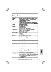
...CAUTION 3) - Supports Untied Overclocking Technology (see CAUTION 4) - Southbridge: VIA® VT8237S - 2 x DDR DIMM slots - CPU Frequency Stepless Control (see CAUTION 2) - Boot Failure Guard (B.F.G.) - 1 x PCI Express x16 slot - 3 x PCI slots - 1 x HDMR slot - Pixel ...(see CAUTION 6) - 2 x ATA133 IDE connectors (support 4 x IDE devices) - 1 x Floppy connector - 1 x IR header 5 ASRock P4VM900-SATA2 Motherboard English Speed: 10/100 Ethernet - Integrated VIA® Delta Chrome Graphics - VIA® PHY VT6103 - shared memory 256MB - 5.1 CH ...
...CAUTION 3) - Supports Untied Overclocking Technology (see CAUTION 4) - Southbridge: VIA® VT8237S - 2 x DDR DIMM slots - CPU Frequency Stepless Control (see CAUTION 2) - Boot Failure Guard (B.F.G.) - 1 x PCI Express x16 slot - 3 x PCI slots - 1 x HDMR slot - Pixel ...(see CAUTION 6) - 2 x ATA133 IDE connectors (support 4 x IDE devices) - 1 x Floppy connector - 1 x IR header 5 ASRock P4VM900-SATA2 Motherboard English Speed: 10/100 Ethernet - Integrated VIA® Delta Chrome Graphics - VIA® PHY VT6103 - shared memory 256MB - 5.1 CH ...
Quick Installation Guide
Page 6
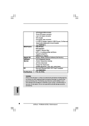
... Tachometer - Voltage Monitoring: +12V, +5V, +3.3V, Vcore - English 6 ASRock P4VM900-SATA2 Motherboard Microsoft® Windows® 2000 / XP / VistaTM compliant (see CAUTION 7) - 4Mb AMI BIOS - CPU/Chassis FAN connector - 20 pin ATX power connector - 4 pin 12V power connector - AMBIOS 2.3.1 Support - CPU Temperature Sensing - FCC, CE, WHQL WARNING Please realize that there is a certain risk involved...
... Tachometer - Voltage Monitoring: +12V, +5V, +3.3V, Vcore - English 6 ASRock P4VM900-SATA2 Motherboard Microsoft® Windows® 2000 / XP / VistaTM compliant (see CAUTION 7) - 4Mb AMI BIOS - CPU/Chassis FAN connector - 20 pin ATX power connector - 4 pin 12V power connector - AMBIOS 2.3.1 Support - CPU Temperature Sensing - FCC, CE, WHQL WARNING Please realize that there is a certain risk involved...


