User Manual
Page 6
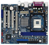
...6 x Ready-to-Use USB 2.0 Ports - 1 x RJ-45 LAN Port - Supports Untied Overclocking Technology (see CAUTION 5) - Support DDR400/333 - ASRock U-COP (see CAUTION 2) - Pixel Shader 2.0, DirectX 9.0 VGA - Micro ATX Form Factor: 9.6-in x 8.0-in /Front Speaker/Microphone - 2 x SATAII...x Floppy connector - 1 x IR header 6 Integrated VIA® Delta Chrome Graphics - Socket 478 for Intel® Pentium® 4 / Celeron® D (Prescott, Northwood, Willamate) processors - Max. Supports Wake-On-LAN ASRock 6CH I /O Connector - Max. Southbridge: VIA® VT8237S - 2 x DDR DIMM...
...6 x Ready-to-Use USB 2.0 Ports - 1 x RJ-45 LAN Port - Supports Untied Overclocking Technology (see CAUTION 5) - Support DDR400/333 - ASRock U-COP (see CAUTION 2) - Pixel Shader 2.0, DirectX 9.0 VGA - Micro ATX Form Factor: 9.6-in x 8.0-in /Front Speaker/Microphone - 2 x SATAII...x Floppy connector - 1 x IR header 6 Integrated VIA® Delta Chrome Graphics - Socket 478 for Intel® Pentium® 4 / Celeron® D (Prescott, Northwood, Willamate) processors - Max. Supports Wake-On-LAN ASRock 6CH I /O Connector - Max. Southbridge: VIA® VT8237S - 2 x DDR DIMM...
User Manual
Page 13
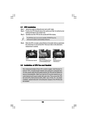
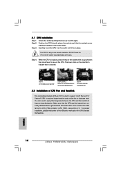
... Step 1. It requires larger heatsink and cooling fan to improve heat dissipation. The lever clicks on the socket while you push down the socket lever to the instruction manuals of the socket lever. When the CPU is locked. Step 2. You also need to spray thermal grease between the CPU... and the heatsink to dissipate heat. Carefully insert the CPU into the socket to avoid bending of CPU Fan and Heatsink This motherboard adopts 478-pin CPU socket to support Intel® Pentium® 4 / Celeron® CPU. Make sure that its marked...
... Step 1. It requires larger heatsink and cooling fan to improve heat dissipation. The lever clicks on the socket while you push down the socket lever to the instruction manuals of the socket lever. When the CPU is locked. Step 2. You also need to spray thermal grease between the CPU... and the heatsink to dissipate heat. Carefully insert the CPU into the socket to avoid bending of CPU Fan and Heatsink This motherboard adopts 478-pin CPU socket to support Intel® Pentium® 4 / Celeron® CPU. Make sure that its marked...
Quick Installation Guide
Page 5
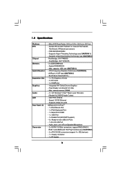
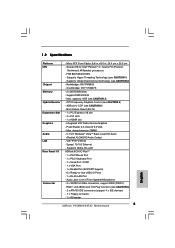
... Hyper-Threading Technology (see CAUTION 3) - Support DDR400/333 - Max. Socket 478 for Intel® Pentium® 4 / Celeron® D (Prescott, Northwood, Willamate) processors - capacity: 4GB (see CAUTION 1) - CPU Frequency Stepless Control (see CAUTION 6) - 2 x ATA133 IDE connectors (support 4 x IDE devices) - 1 x Floppy connector - 1 x IR header 5 ASRock P4VM900-SATA2 Motherboard English shared memory 256MB - 5.1 CH Windows® VistaTM Basic...
... Hyper-Threading Technology (see CAUTION 3) - Support DDR400/333 - Max. Socket 478 for Intel® Pentium® 4 / Celeron® D (Prescott, Northwood, Willamate) processors - capacity: 4GB (see CAUTION 1) - CPU Frequency Stepless Control (see CAUTION 6) - 2 x ATA133 IDE connectors (support 4 x IDE devices) - 1 x Floppy connector - 1 x IR header 5 ASRock P4VM900-SATA2 Motherboard English shared memory 256MB - 5.1 CH Windows® VistaTM Basic...
Quick Installation Guide
Page 10
... manuals of CPU Fan and Heatsink This motherboard adopts 478-pin CPU socket to support Intel® Pentium® 4 / Celeron® CPU. Carefully insert the CPU into the socket to The Socket Marked Corner STEP 4: Push Down And Lock The Socket Lever 2.2 Installation of the CPU fan and the heatsink...the CPU. When the CPU is locked. English 10 ASRock P4VM900-SATA2 Motherboard DO NOT force the CPU into the socket until it fits in one correct orientation. Step 4. The lever clicks on the socket while you push down the socket lever to indicate that its marked corner matches the ...
... manuals of CPU Fan and Heatsink This motherboard adopts 478-pin CPU socket to support Intel® Pentium® 4 / Celeron® CPU. Carefully insert the CPU into the socket to The Socket Marked Corner STEP 4: Push Down And Lock The Socket Lever 2.2 Installation of the CPU fan and the heatsink...the CPU. When the CPU is locked. English 10 ASRock P4VM900-SATA2 Motherboard DO NOT force the CPU into the socket until it fits in one correct orientation. Step 4. The lever clicks on the socket while you push down the socket lever to indicate that its marked corner matches the ...
