User Manual
Page 5
... ATA (SATA) Cable (Optional) One Serial ATA (SATA) HDD Power Cable (Optional) One ASRock 6CH I/O PlusTM Shield 5 www.asrock.com/support/index.asp 1.1 Package Contents ASRock P4VM900-SATA2 Motherboard (Micro ATX Form Factor: 9.6-in x 8.0-in, 24.4 cm x 20.3 cm) ASRock P4VM900-SATA2 Quick Installation Guide ASRock P4VM900-SATA2 Support CD One 80-conductor Ultra ATA 66/100/133 IDE Ribbon Cable...
... ATA (SATA) Cable (Optional) One Serial ATA (SATA) HDD Power Cable (Optional) One ASRock 6CH I/O PlusTM Shield 5 www.asrock.com/support/index.asp 1.1 Package Contents ASRock P4VM900-SATA2 Motherboard (Micro ATX Form Factor: 9.6-in x 8.0-in, 24.4 cm x 20.3 cm) ASRock P4VM900-SATA2 Quick Installation Guide ASRock P4VM900-SATA2 Support CD One 80-conductor Ultra ATA 66/100/133 IDE Ribbon Cable...

Quick Installation Guide
Page 1
...purchaser for backup purpose, without written consent of the FCC Rules. This device complies with Part 15 of ASRock Inc. When you discard the Lithium battery in California, USA, please follow the related regulations in this ...ASRock. Operation is subject to change without intent to the implied warranties or conditions of such damages arising from any kind, either expressed or implied, including but not limited to infringe. In no responsibility for a particular purpose. Products and corporate names appearing in advance. All rights reserved. 1 ASRock P4VM900-SATA2...
...purchaser for backup purpose, without written consent of the FCC Rules. This device complies with Part 15 of ASRock Inc. When you discard the Lithium battery in California, USA, please follow the related regulations in this ...ASRock. Operation is subject to change without intent to the implied warranties or conditions of such damages arising from any kind, either expressed or implied, including but not limited to infringe. In no responsibility for a particular purpose. Products and corporate names appearing in advance. All rights reserved. 1 ASRock P4VM900-SATA2...
Quick Installation Guide
Page 2
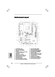
... 3 x PCI Slots (PCI1- 3) 24 PCI Express x16 Slot (PCIE1) 25 ATX Power Connector (ATXPWR1) 26 Shared USB 2.0 Header (USB4_5, Blue) 27 CPU Fan Connector (CPU_FAN1) 2 ASRock P4VM900-SATA2 Motherboard
... 3 x PCI Slots (PCI1- 3) 24 PCI Express x16 Slot (PCIE1) 25 ATX Power Connector (ATXPWR1) 26 Shared USB 2.0 Header (USB4_5, Blue) 27 CPU Fan Connector (CPU_FAN1) 2 ASRock P4VM900-SATA2 Motherboard
Quick Installation Guide
Page 3
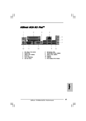
ASRock 6CH I/O PlusTM 1 PS/2 Mouse Port (Green) 2 Parallel Port 3 USB 2.0 Ports (USB23) 4 RJ-45 Port 5 Line In (Light Blue) 6 Line Out (Lime) 7 Microphone (Pink) 8 Shared USB 2.0 Ports (USB45) 9 USB 2.0 Ports (USB01) 10 VGA Port 11 COM Port 12 PS/2 Keyboard Port (Purple) English 3 ASRock P4VM900-SATA2 Motherboard
ASRock 6CH I/O PlusTM 1 PS/2 Mouse Port (Green) 2 Parallel Port 3 USB 2.0 Ports (USB23) 4 RJ-45 Port 5 Line In (Light Blue) 6 Line Out (Lime) 7 Microphone (Pink) 8 Shared USB 2.0 Ports (USB45) 9 USB 2.0 Ports (USB01) 10 VGA Port 11 COM Port 12 PS/2 Keyboard Port (Purple) English 3 ASRock P4VM900-SATA2 Motherboard

Quick Installation Guide
Page 4
... software might be updated, the content of this manual will be available on ASRock website as well. www.asrock.com/support/index.asp 1.1 Package Contents ASRock P4VM900-SATA2 Motherboard (Micro ATX Form Factor: 9.6-in x 8.0-in, 24.4 cm x 20.3 cm) ASRock P4VM900-SATA2 Quick Installation Guide ASRock P4VM900-SATA2 Support CD One 80-conductor Ultra ATA 66/100/133 IDE Ribbon Cable...
... software might be updated, the content of this manual will be available on ASRock website as well. www.asrock.com/support/index.asp 1.1 Package Contents ASRock P4VM900-SATA2 Motherboard (Micro ATX Form Factor: 9.6-in x 8.0-in, 24.4 cm x 20.3 cm) ASRock P4VM900-SATA2 Quick Installation Guide ASRock P4VM900-SATA2 Support CD One 80-conductor Ultra ATA 66/100/133 IDE Ribbon Cable...
Quick Installation Guide
Page 5
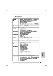
...9.0 VGA - Supports Hyper-Threading Technology (see CAUTION 4) - Southbridge: VIA® VT8237S - 2 x DDR DIMM slots - ASRock U-COP (see CAUTION 3) - Integrated VIA® Delta Chrome Graphics - shared memory 256MB - 5.1 CH Windows® VistaTM Basic... Overclocking Technology (see CAUTION 6) - 2 x ATA133 IDE connectors (support 4 x IDE devices) - 1 x Floppy connector - 1 x IR header 5 ASRock P4VM900-SATA2 Motherboard English 1.2 Specifications Platform CPU Chipset Memory Hybrid Booster Expansion Slot Graphics Audio LAN Rear Panel I /O PlusTM - 1 x PS/2 Mouse Port - 1 ...
...9.0 VGA - Supports Hyper-Threading Technology (see CAUTION 4) - Southbridge: VIA® VT8237S - 2 x DDR DIMM slots - ASRock U-COP (see CAUTION 3) - Integrated VIA® Delta Chrome Graphics - shared memory 256MB - 5.1 CH Windows® VistaTM Basic... Overclocking Technology (see CAUTION 6) - 2 x ATA133 IDE connectors (support 4 x IDE devices) - 1 x Floppy connector - 1 x IR header 5 ASRock P4VM900-SATA2 Motherboard English 1.2 Specifications Platform CPU Chipset Memory Hybrid Booster Expansion Slot Graphics Audio LAN Rear Panel I /O PlusTM - 1 x PS/2 Mouse Port - 1 ...
Quick Installation Guide
Page 6
... affect your system stability, or even cause damage to the components and devices of them are not responsible for possible damage caused by overclocking. English 6 ASRock P4VM900-SATA2 Motherboard Front panel audio connector - 2 x USB 2.0 headers (support 4 USB 2.0 ports; 2 of your own risk and expense. Supports "Plug and Play" - AMBIOS 2.3.1 Support - Supports jumperfree - Drivers...
... affect your system stability, or even cause damage to the components and devices of them are not responsible for possible damage caused by overclocking. English 6 ASRock P4VM900-SATA2 Motherboard Front panel audio connector - 2 x USB 2.0 headers (support 4 USB 2.0 ports; 2 of your own risk and expense. Supports "Plug and Play" - AMBIOS 2.3.1 Support - Supports jumperfree - Drivers...
Quick Installation Guide
Page 7
...® VistaTM. 4. Power Management for Microsoft® Windows® VistaTM driver and related information. To improve heat dissipation, remember to SATAII connector directly. 7. ASRock website http://www.asrock.com 7 ASRock P4VM900-SATA2 Motherboard English This motherboard supports Untied Overclocking Technology. Although this motherboard offers stepless control, it back again. About the setting of "Hyper Threading...
...® VistaTM. 4. Power Management for Microsoft® Windows® VistaTM driver and related information. To improve heat dissipation, remember to SATAII connector directly. 7. ASRock website http://www.asrock.com 7 ASRock P4VM900-SATA2 Motherboard English This motherboard supports Untied Overclocking Technology. Although this motherboard offers stepless control, it back again. About the setting of "Hyper Threading...

Quick Installation Guide
Page 8
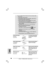
... memory size above 512MB and plan to submit Windows® VistaTM Basic logo, please adjust the shared memory size of onboard VGA to 64MB. English 8 ASRock P4VM900-SATA2 Motherboard If you use onboard VGA with total system memory size 512MB and plan to submit Windows® VistaTM Basic logo, please adjust the shared...
... memory size above 512MB and plan to submit Windows® VistaTM Basic logo, please adjust the shared memory size of onboard VGA to 64MB. English 8 ASRock P4VM900-SATA2 Motherboard If you use onboard VGA with total system memory size 512MB and plan to submit Windows® VistaTM Basic logo, please adjust the shared...
Quick Installation Guide
Page 9
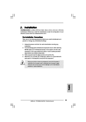
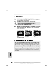
...your motherboard directly on a grounded antistatic pad or in , 24.4 cm x 20.3 cm) motherboard. Failure to the motherboard, peripherals, and/or components. 9 ASRock P4VM900-SATA2 Motherboard English Hold components by the edges and do so may cause severe damage to do not touch the ICs. 4. Installation... P4VM900-SATA2 is detached from the wall socket before you install or remove any component. 2. Before you handle components. 3. To avoid damaging the ...
...your motherboard directly on a grounded antistatic pad or in , 24.4 cm x 20.3 cm) motherboard. Failure to the motherboard, peripherals, and/or components. 9 ASRock P4VM900-SATA2 Motherboard English Hold components by the edges and do so may cause severe damage to do not touch the ICs. 4. Installation... P4VM900-SATA2 is detached from the wall socket before you install or remove any component. 2. Before you handle components. 3. To avoid damaging the ...
Quick Installation Guide
Page 10
... socket lever to avoid bending of the CPU fan and the heatsink. It requires larger heatsink and cooling fan to improve heat dissipation. English 10 ASRock P4VM900-SATA2 Motherboard Step 4. You also need to spray thermal grease between the CPU and the heatsink to dissipate heat. 2.1 CPU Installation Step 1. Step 2. Lift Lever Up...
... socket lever to avoid bending of the CPU fan and the heatsink. It requires larger heatsink and cooling fan to improve heat dissipation. English 10 ASRock P4VM900-SATA2 Motherboard Step 4. You also need to spray thermal grease between the CPU and the heatsink to dissipate heat. 2.1 CPU Installation Step 1. Step 2. Lift Lever Up...
Quick Installation Guide
Page 11
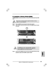
Step 2. The DIMM only fits in place and the DIMM is properly seated. 11 ASRock P4VM900-SATA2 Motherboard English Align a DIMM on the slot such that the notch on the DIMM matches the break on the slot. It will cause permanent damage ... motherboard and the DIMM if you force the DIMM into the slot until the retaining clips at incorrect orientation. Step 3. 2.3 Installation of Memory Modules (DIMM) P4VM900-SATA2 motherboard provides two 184-pin DDR (Double Data Rate) DIMM slots. Firmly insert the DIMM into the slot at both ends fully snap back in...
Step 2. The DIMM only fits in place and the DIMM is properly seated. 11 ASRock P4VM900-SATA2 Motherboard English Align a DIMM on the slot such that the notch on the DIMM matches the break on the slot. It will cause permanent damage ... motherboard and the DIMM if you force the DIMM into the slot until the retaining clips at incorrect orientation. Step 3. 2.3 Installation of Memory Modules (DIMM) P4VM900-SATA2 motherboard provides two 184-pin DDR (Double Data Rate) DIMM slots. Firmly insert the DIMM into the slot at both ends fully snap back in...
Quick Installation Guide
Page 12
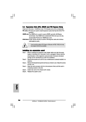
... facing the slot that the power supply is switched off or the power cord is completely seated on the slot. Replace the system cover. 12 ASRock P4VM900-SATA2 Motherboard English Step 5. Align the card connector with screws. you install the add-on this motherboard. Step 2. HDMR slot: The HDMR slot is already installed...
... facing the slot that the power supply is switched off or the power cord is completely seated on the slot. Replace the system cover. 12 ASRock P4VM900-SATA2 Motherboard English Step 5. Align the card connector with screws. you install the add-on this motherboard. Step 2. HDMR slot: The HDMR slot is already installed...
Quick Installation Guide
Page 13
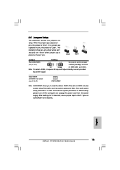
... illustration shows a 3-pin jumper whose pin1 and pin2 are setup. The data in CMOS. After waiting for PS/2 or USB wake up events. English 13 ASRock P4VM900-SATA2 Motherboard Short Open Jumper Setting PS2_USB_PWR1 Short pin2, pin3 to enable (see p.2, No. 19) 2-pin jumper Note: CLRCMOS1 allows you to clear the data in...
... illustration shows a 3-pin jumper whose pin1 and pin2 are setup. The data in CMOS. After waiting for PS/2 or USB wake up events. English 13 ASRock P4VM900-SATA2 Motherboard Short Open Jumper Setting PS2_USB_PWR1 Short pin2, pin3 to enable (see p.2, No. 19) 2-pin jumper Note: CLRCMOS1 allows you to clear the data in...
Quick Installation Guide
Page 14
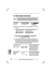
...-striped side to the IDE devices 80-conductor ATA 66/100/133 cable Note: If you use only one IDE device on the motherboard. 14 ASRock P4VM900-SATA2 Motherboard English Primary IDE Connector (Blue) Secondary IDE Connector (Black) (39-pin IDE1, see p.2, No. 10) (39-pin IDE2, see p.2, No. 14) SATAII_2 SATAII_1 These...
...-striped side to the IDE devices 80-conductor ATA 66/100/133 cable Note: If you use only one IDE device on the motherboard. 14 ASRock P4VM900-SATA2 Motherboard English Primary IDE Connector (Blue) Secondary IDE Connector (Black) (39-pin IDE1, see p.2, No. 10) (39-pin IDE2, see p.2, No. 14) SATAII_2 SATAII_1 These...
Quick Installation Guide
Page 15
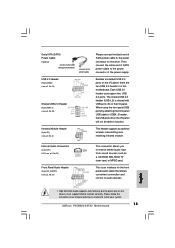
... to the power connector of the power supply. English 1. Besides six default USB 2.0 ports on the chassis must support HDA to install your system. 15 ASRock P4VM900-SATA2 Motherboard High Definition Audio supports Jack Sensing, but the panel wire on the I /O panel. Each USB 2.0 header can support two USB 2.0 ports. The shared USB...
... to the power connector of the power supply. English 1. Besides six default USB 2.0 ports on the chassis must support HDA to install your system. 15 ASRock P4VM900-SATA2 Motherboard High Definition Audio supports Jack Sensing, but the panel wire on the I /O panel. Each USB 2.0 header can support two USB 2.0 ports. The shared USB...
Quick Installation Guide
Page 16
Connect Audio_R (RIN) to OUT2_R and Audio_L (LIN) to the ground pin. 16 ASRock P4VM900-SATA2 Motherboard D. Enter Windows system. For Windows® 2000 / XP OS: Click "Audio I/O", select "Connector Settings" , choose "Disable front panel jack detection", and save the change ...
Connect Audio_R (RIN) to OUT2_R and Audio_L (LIN) to the ground pin. 16 ASRock P4VM900-SATA2 Motherboard D. Enter Windows system. For Windows® 2000 / XP OS: Click "Audio I/O", select "Connector Settings" , choose "Disable front panel jack detection", and save the change ...
Quick Installation Guide
Page 17
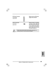
ATX 12V Connector (4-pin ATX12V1) (see p.2, No. 25) Please connect an ATX power supply to this connector so that it may cause permanent damage! Please install the heatsink and the CPU fan before installing ATX 12V connector; English 17 ASRock P4VM900-SATA2 Motherboard Failing to do so will cause the failure to power up. otherwise, it can provides sufficient power. ATX Power Connector (20-pin ATXPWR1) (see p.2, No. 2) Please note that it is necessary to connect a power supply with ATX 12V plug to this connector.
ATX 12V Connector (4-pin ATX12V1) (see p.2, No. 25) Please connect an ATX power supply to this connector so that it may cause permanent damage! Please install the heatsink and the CPU fan before installing ATX 12V connector; English 17 ASRock P4VM900-SATA2 Motherboard Failing to do so will cause the failure to power up. otherwise, it can provides sufficient power. ATX Power Connector (20-pin ATXPWR1) (see p.2, No. 2) Please note that it is necessary to connect a power supply with ATX 12V plug to this connector.
Quick Installation Guide
Page 18
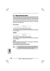
... different vendors, the jumper pin setting methods may not be the same. HITACHI Please use the Feature Tool, a DOS-bootable tool, for the updates. 18 ASRock P4VM900-SATA2 Motherboard English otherwise, your reference. SAMSUNG If pin 3 and pin 4 are just for your SATAII hard disk may fail to run at SATAII mode, which...
... different vendors, the jumper pin setting methods may not be the same. HITACHI Please use the Feature Tool, a DOS-bootable tool, for the updates. 18 ASRock P4VM900-SATA2 Motherboard English otherwise, your reference. SAMSUNG If pin 3 and pin 4 are just for your SATAII hard disk may fail to run at SATAII mode, which...
Quick Installation Guide
Page 19
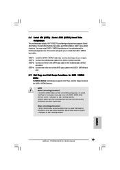
... this motherboard for the action to insert and remove the SATA / SATAII HDDs while the system is still power-on and in working condition. 19 ASRock P4VM900-SATA2 Motherboard English However, please note that supports Serial ATA (SATA) / Serial ATAII (SATAII) hard disks and RAID (RAID 0, RAID 1 and JBOD) ... 2: Connect the SATA power cable to the SATA / SATAII hard disk. 2.9 Hot Plug and Hot Swap Functions for SATA / SATAII HDDs P4VM900-SATA2 motherboard supports Hot Plug and Hot Swap functions for the action to insert and remove the SATA / SATAII HDDs while the system is still power...
... this motherboard for the action to insert and remove the SATA / SATAII HDDs while the system is still power-on and in working condition. 19 ASRock P4VM900-SATA2 Motherboard English However, please note that supports Serial ATA (SATA) / Serial ATAII (SATAII) hard disks and RAID (RAID 0, RAID 1 and JBOD) ... 2: Connect the SATA power cable to the SATA / SATAII hard disk. 2.9 Hot Plug and Hot Swap Functions for SATA / SATAII HDDs P4VM900-SATA2 motherboard supports Hot Plug and Hot Swap functions for the action to insert and remove the SATA / SATAII HDDs while the system is still power...


