User Manual
Page 3
...SATA) / Serial ATAII (SATAII) Hard Disks Installation 22 2.9 Hot Plug and Hot Swap Functions for Windows® VistaTM Basic Logo 9 1.4 Motherboard Layout 10 1.5 ASRock 6CH I/O Plus 11 TM 2. Introduction 5 1.1 Package Contents 5 1.2 Specifications 6 1.3 Minimum Hardware Requirement Table for SATA / SATAII HDDs 22 2.10 SATA / SATAII...Functions 26 2.14 Installing Windows® 2000 / XP / VistaTM Without RAID Functions 27 2.15 Untied Overclocking Technology 27 3. BIOS SETUP UTILITY 28 3.1 Introduction 28 3.1.1 BIOS Menu Bar 28 3.1.2 Navigation Keys 29 3.2 Main Screen 29 3
...SATA) / Serial ATAII (SATAII) Hard Disks Installation 22 2.9 Hot Plug and Hot Swap Functions for Windows® VistaTM Basic Logo 9 1.4 Motherboard Layout 10 1.5 ASRock 6CH I/O Plus 11 TM 2. Introduction 5 1.1 Package Contents 5 1.2 Specifications 6 1.3 Minimum Hardware Requirement Table for SATA / SATAII HDDs 22 2.10 SATA / SATAII...Functions 26 2.14 Installing Windows® 2000 / XP / VistaTM Without RAID Functions 27 2.15 Untied Overclocking Technology 27 3. BIOS SETUP UTILITY 28 3.1 Introduction 28 3.1.1 BIOS Menu Bar 28 3.1.2 Navigation Keys 29 3.2 Main Screen 29 3
User Manual
Page 5
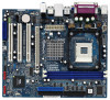
...In case any modifications of this motherboard, please visit our website for a 3.5-in , 24.4 cm x 20.3 cm) ASRock P4VM900-SATA2 Quick Installation Guide ASRock P4VM900-SATA2 Support CD One 80-conductor Ultra ATA 66/100/133 IDE Ribbon Cable One Ribbon Cable for specific information about the model you...latest VGA cards and CPU support lists on ASRock website without notice. Introduction Thank you are using. In this manual occur, the updated version will be available on ASRock website as well. Because the motherboard specifications and the BIOS software might be updated, the content of...
...In case any modifications of this motherboard, please visit our website for a 3.5-in , 24.4 cm x 20.3 cm) ASRock P4VM900-SATA2 Quick Installation Guide ASRock P4VM900-SATA2 Support CD One 80-conductor Ultra ATA 66/100/133 IDE Ribbon Cable One Ribbon Cable for specific information about the model you...latest VGA cards and CPU support lists on ASRock website without notice. Introduction Thank you are using. In this manual occur, the updated version will be available on ASRock website as well. Because the motherboard specifications and the BIOS software might be updated, the content of...
User Manual
Page 7
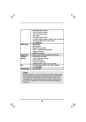
...; 2 of your own risk and expense. Supports "Plug and Play" - Voltage Monitoring: +12V, +5V, +3.3V, Vcore - CD in the BIOS, applying Untied Overclocking Technology, or using the thirdparty overclocking tools. CPU Temperature Sensing - We are shared with overclocking, including adjusting the setting in header -...WARNING Please realize that there is a certain risk involved with USB45 ports on the I/O panel) (see CAUTION 8) - BIOS Feature Support CD Hardware Monitor OS Certifications - Supports jumperfree - Microsoft® Windows® 2000 / XP / VistaTM compliant (see CAUTION 7) ...
...; 2 of your own risk and expense. Supports "Plug and Play" - Voltage Monitoring: +12V, +5V, +3.3V, Vcore - CD in the BIOS, applying Untied Overclocking Technology, or using the thirdparty overclocking tools. CPU Temperature Sensing - We are shared with overclocking, including adjusting the setting in header -...WARNING Please realize that there is a certain risk involved with USB45 ports on the I/O panel) (see CAUTION 8) - BIOS Feature Support CD Hardware Monitor OS Certifications - Supports jumperfree - Microsoft® Windows® 2000 / XP / VistaTM compliant (see CAUTION 7) ...
User Manual
Page 10
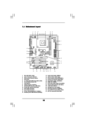
...) DDR2 (64/72 bit, 184-pin module) 1 IR1 Super I/O 4Mb BIOS 7 8 9 FLOPPY1 24.4cm (9.6 in) PCI EXPRESS FSB800 DDR400 1 Top: Line In Center: Line Out Bottom: Mic In 24 23 22 PCIE1 LAN PHY IDE1 IDE2 CMOS Battery CD1 PCI 1 P4VM900-SATA2 PCI 2 VIA VT8237S Audio CODEC 1 HD_AUDIO1 PCI 3 USB2.0 CHA_FAN1 CLRCMOS1 HDMR1...
...) DDR2 (64/72 bit, 184-pin module) 1 IR1 Super I/O 4Mb BIOS 7 8 9 FLOPPY1 24.4cm (9.6 in) PCI EXPRESS FSB800 DDR400 1 Top: Line In Center: Line Out Bottom: Mic In 24 23 22 PCIE1 LAN PHY IDE1 IDE2 CMOS Battery CD1 PCI 1 P4VM900-SATA2 PCI 2 VIA VT8237S Audio CODEC 1 HD_AUDIO1 PCI 3 USB2.0 CHA_FAN1 CLRCMOS1 HDMR1...
User Manual
Page 19
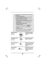
...+ 1 SPEAKER DUMMY DUMMY +5V This header accommodates several system front panel functions. Connect Audio_R (RIN) to OUT2_R and Audio_L (LIN) to the ground pin. Enter BIOS Setup Utility. Enter Windows system. Please connect the CPU fan cable to this header. MIC_RET and OUT_RET are for AC'97 audio panel. If you...
...+ 1 SPEAKER DUMMY DUMMY +5V This header accommodates several system front panel functions. Connect Audio_R (RIN) to OUT2_R and Audio_L (LIN) to the ground pin. Enter BIOS Setup Utility. Enter Windows system. Please connect the CPU fan cable to this header. MIC_RET and OUT_RET are for AC'97 audio panel. If you...
User Manual
Page 25
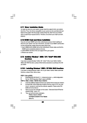
... please follow below then. 1. Therefore, the drivers you will see the message on this motherboard. Enter BIOS SETUP UTILITY Advanced screen IDE Configuration. A. Please select CD- 2.11 Driver Installation Guide To install the ...your SATA / SATAII HDDs with RAID functions, please follow below steps. C. Install HDMR card driver from up BIOS. A 2. Set the "SATA Operation Mode" option to use HDMR card function on the screen, "Generate Serial... [RAID]. A. STEP 2: Make a SATA / SATAII driver diskette. Insert the ASRock Support CD into floppy drive A: 25
... please follow below then. 1. Therefore, the drivers you will see the message on this motherboard. Enter BIOS SETUP UTILITY Advanced screen IDE Configuration. A. Please select CD- 2.11 Driver Installation Guide To install the ...your SATA / SATAII HDDs with RAID functions, please follow below steps. C. Install HDMR card driver from up BIOS. A 2. Set the "SATA Operation Mode" option to use HDMR card function on the screen, "Generate Serial... [RAID]. A. STEP 2: Make a SATA / SATAII driver diskette. Insert the ASRock Support CD into floppy drive A: 25

User Manual
Page 26
...and press any key to start to format the floppy diskette and copy SATA / SATAII drivers into the floppy diskette. B. page, please insert the ASRock Support CD into your optical drive, and click the "Load Driver" button on the left on your system. STEP 3: Use "RAID Installation Guide... Windows® environment, please install SATA / SATAII drivers from the Support CD again so that "VIA RAID Tool" will be presented. Enter BIOS SETUP UTILITY Advanced screen IDE Configuration. Before you want to install Windows® 2000 / XP OS on your system. Please refer to boot ...
...and press any key to start to format the floppy diskette and copy SATA / SATAII drivers into the floppy diskette. B. page, please insert the ASRock Support CD into your optical drive, and click the "Load Driver" button on the left on your system. STEP 3: Use "RAID Installation Guide... Windows® environment, please install SATA / SATAII drivers from the Support CD again so that "VIA RAID Tool" will be presented. Enter BIOS SETUP UTILITY Advanced screen IDE Configuration. Before you want to install Windows® 2000 / XP OS on your system. Please refer to boot ...
User Manual
Page 27
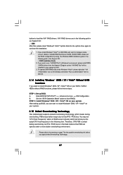
...drive again to manage (create, convert, delete or rebuild) RAID functions on SATA / SATAII HDDs, please set "CPU Host Frequency" option of BIOS setup to [Auto], which means during overclocking, but PCI / PCIE bus is untied during overclocking, FSB enjoys better margin due to fixed PCI...to execute. 2.14 Installing Windows® 2000 / XP / VistaTM Without RAID Functions If you want to continue the installation. 1. After setting up BIOS. Please refer to the warning on page 7 for the possible overclocking risk before you can operate under Windows® VistaTM, please right-click "...
...drive again to manage (create, convert, delete or rebuild) RAID functions on SATA / SATAII HDDs, please set "CPU Host Frequency" option of BIOS setup to [Auto], which means during overclocking, but PCI / PCIE bus is untied during overclocking, FSB enjoys better margin due to fixed PCI...to execute. 2.14 Installing Windows® 2000 / XP / VistaTM Without RAID Functions If you want to continue the installation. 1. After setting up BIOS. Please refer to the warning on page 7 for the possible overclocking risk before you can operate under Windows® VistaTM, please right-click "...
User Manual
Page 28
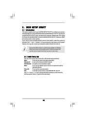
...the screen has a menu bar with the following selections: Main To set up the system time/date information Advanced To set up the advanced BIOS features H/W Monitor To display current hardware status Boot To set up the default system device to locate and load the Operating System Security To... set up the computer. If you see on . BIOS SETUP UTILITY 3.1 Introduction This section explains how to use the BIOS SETUP UTILITY to enter the BIOS SETUP UTILITY after POST, restart the system by pressing + + , or by turning the system off ...
...the screen has a menu bar with the following selections: Main To set up the system time/date information Advanced To set up the advanced BIOS features H/W Monitor To display current hardware status Boot To set up the default system device to locate and load the Operating System Security To... set up the computer. If you see on . BIOS SETUP UTILITY 3.1 Introduction This section explains how to use the BIOS SETUP UTILITY to enter the BIOS SETUP UTILITY after POST, restart the system by pressing + + , or by turning the system off ...
User Manual
Page 29
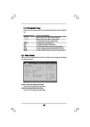
... Keys Please check the following table for all the settings To save changes and exit the BIOS SETUP UTILITY To jump to the Exit Screen or exit the current screen 3.2 Main Screen When you enter the BIOS SETUP UTILITY, the Main screen will appear and display the system overview... UTILITY Main Advanced H/W Monitor Boot Security Exit System Overview System Time System Date [16:15:31] [Mon 08/20/2007] BIOS Version : P4VM900-SATA2 BIOS P1.00 Processor Type : Intel (R) CPU 2.80GHz Processor Speed : 2800MHz Microcode Update : F34/17 Cache Size : 256KB Total Memory DDR1 DDR2 : ...
... Keys Please check the following table for all the settings To save changes and exit the BIOS SETUP UTILITY To jump to the Exit Screen or exit the current screen 3.2 Main Screen When you enter the BIOS SETUP UTILITY, the Main screen will appear and display the system overview... UTILITY Main Advanced H/W Monitor Boot Security Exit System Overview System Time System Date [16:15:31] [Mon 08/20/2007] BIOS Version : P4VM900-SATA2 BIOS P1.00 Processor Type : Intel (R) CPU 2.80GHz Processor Speed : 2800MHz Microcode Update : F34/17 Cache Size : 256KB Total Memory DDR1 DDR2 : ...
User Manual
Page 30
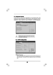
... wrong values in this motherboard. CPU Host Frequency While entering setup, BIOS auto detects the present CPU host frequency of this section may cause the system to malfunction. BIOS SETUP UTILITY Main Advanced H/W Monitor Boot Security Exit Advanced Settings WARNING ... Copyright 1985-2003, American Megatrends, Inc. 3.3 Advanced Screen In this section, you may cause system to malfunction. 3.3.1 CPU Configuration BIOS SETUP UTILITY Advanced CPU Configuration CPU Host Frequency Actual Frequency (MHz) Boot Failure Guard Spread Spectrum PCIE clock operation mode [Auto] [...
... wrong values in this motherboard. CPU Host Frequency While entering setup, BIOS auto detects the present CPU host frequency of this section may cause the system to malfunction. BIOS SETUP UTILITY Main Advanced H/W Monitor Boot Security Exit Advanced Settings WARNING ... Copyright 1985-2003, American Megatrends, Inc. 3.3 Advanced Screen In this section, you may cause system to malfunction. 3.3.1 CPU Configuration BIOS SETUP UTILITY Advanced CPU Configuration CPU Host Frequency Actual Frequency (MHz) Boot Failure Guard Spread Spectrum PCIE clock operation mode [Auto] [...
User Manual
Page 32
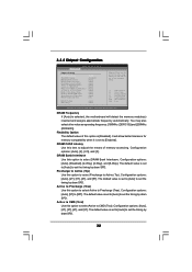
... can be set by dram SPD. Configuration options: [Auto], [2], [2.5], and [3]. Active to CMD (Trcd) Use this option to select Precharge to Active (Trp). 3.3.2 Chipset Configuration BIOS SETUP UTILITY Advanced Chipset Settings DRAM Frequency Flexibility Option DRAM CAS# Latency DRAM Bank Interleave Precharge to Active (Trp) Active to Precharge (Tras) Active to...
... can be set by dram SPD. Configuration options: [Auto], [2], [2.5], and [3]. Active to CMD (Trcd) Use this option to select Precharge to Active (Trp). 3.3.2 Chipset Configuration BIOS SETUP UTILITY Advanced Chipset Settings DRAM Frequency Flexibility Option DRAM CAS# Latency DRAM Bank Interleave Precharge to Active (Trp) Active to Precharge (Tras) Active to...
User Manual
Page 35
... enable or disable RTC (Real Time Clock) to turn on the system from the power-soft-off mode. The default value is [Disabled]. 3.3.3 ACPI Configuration BIOS SETUP UTILITY Advanced ACPI Configuration Suspend To RAM Restore on the system. RTC Alarm Power On Use this item to enable or disable Ring-In...
... enable or disable RTC (Real Time Clock) to turn on the system from the power-soft-off mode. The default value is [Disabled]. 3.3.3 ACPI Configuration BIOS SETUP UTILITY Advanced ACPI Configuration Suspend To RAM Restore on the system. RTC Alarm Power On Use this item to enable or disable Ring-In...
User Manual
Page 36
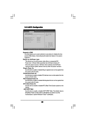
... Defaults Save and Exit Exit v02.54 (C) Copyright 1985-2003, American Megatrends, Inc. Configuration options: [Enabled] and [Disabled]. BIOS SETUP UTILITY Advanced Primary IDE Master Device Vendor Size LBA Mode Block Mode PIO Mode Async DMA Ultra DMA S.M.A.R.T. SATA Operation Mode ...installation. Please set the IDE configuration for the device that you want to enable or disable onboard IDE controller. 3.3.4 IDE Configuration BIOS SETUP UTILITY Advanced IDE Configuration OnBoard IDE Controller SATA Operation Mode [Enabled] [non-RAID] To enable or disable the onboard IDE...
... Defaults Save and Exit Exit v02.54 (C) Copyright 1985-2003, American Megatrends, Inc. Configuration options: [Enabled] and [Disabled]. BIOS SETUP UTILITY Advanced Primary IDE Master Device Vendor Size LBA Mode Block Mode PIO Mode Async DMA Ultra DMA S.M.A.R.T. SATA Operation Mode ...installation. Please set the IDE configuration for the device that you want to enable or disable onboard IDE controller. 3.3.4 IDE Configuration BIOS SETUP UTILITY Advanced IDE Configuration OnBoard IDE Controller SATA Operation Mode [Enabled] [non-RAID] To enable or disable the onboard IDE...
User Manual
Page 37
... Netware and UNIX user, select [Disabled] to enable or disable the S.M.A.R.T. (Self-Monitoring, Analysis, and Reporting Technology) feature. After selecting the hard disk information into BIOS, use of the IDE device that you specify. If this item to enable 32-bit access to select the LBA/Large mode for compatible IDE...
... Netware and UNIX user, select [Disabled] to enable or disable the S.M.A.R.T. (Self-Monitoring, Analysis, and Reporting Technology) feature. After selecting the hard disk information into BIOS, use of the IDE device that you specify. If this item to enable 32-bit access to select the LBA/Large mode for compatible IDE...

User Manual
Page 38
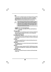
3.3.5 PCIPnP Configuration BIOS SETUP UTILITY Advanced Advanced PCI / PnP Settings PCI Latency Timer PCI IDE BusMaster [32] [Enabled] Value in units of floppy drive connected to the system. +... (C) Copyright 1985-2003, American Megatrends, Inc. 38 PCI IDE BusMaster Use this section, you may configure the type of your floppy drive. It is 32. BIOS SETUP UTILITY Advanced Floppy Configuration Floppy A Floppy B [1.44 MB 312"] [Disabled] Select the type of PCI clocks for PCI device latency timer register. +F1 F9...
3.3.5 PCIPnP Configuration BIOS SETUP UTILITY Advanced Advanced PCI / PnP Settings PCI Latency Timer PCI IDE BusMaster [32] [Enabled] Value in units of floppy drive connected to the system. +... (C) Copyright 1985-2003, American Megatrends, Inc. 38 PCI IDE BusMaster Use this section, you may configure the type of your floppy drive. It is 32. BIOS SETUP UTILITY Advanced Floppy Configuration Floppy A Floppy B [1.44 MB 312"] [Disabled] Select the type of PCI clocks for PCI device latency timer register. +F1 F9...
User Manual
Page 39
... Parallel Port Address Parallel Port Mode EPP Version ECP Mode DMA Channel Parallel Port IRQ [Enabled] [3F8 / IRQ4] [Disabled] [378] [ECP + EPP] [1.9] [DMA3] [IRQ7] Allow BIOS to enable or disable floppy drive controller. Serial Port Address Use this option is [ECP+EPP]. If this item to set to [ECP+EPP], it...
... Parallel Port Address Parallel Port Mode EPP Version ECP Mode DMA Channel Parallel Port IRQ [Enabled] [3F8 / IRQ4] [Disabled] [378] [ECP + EPP] [1.9] [DMA3] [IRQ7] Allow BIOS to enable or disable floppy drive controller. Serial Port Address Use this option is [ECP+EPP]. If this item to set to [ECP+EPP], it...
User Manual
Page 40
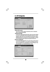
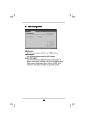
... enable or disable the support to auto-detect; Legacy USB Support Use this item to enable or disable the use of USB controller. 3.3.8 USB Configuration BIOS SETUP UTILITY Advanced USB Configuration USB Controller USB 2.0 Support Legacy USB Support [Enabled] [Enabled] [Disabled] To enable or disable the onboard USB controllers. +F1 F9...
... enable or disable the support to auto-detect; Legacy USB Support Use this item to enable or disable the use of USB controller. 3.3.8 USB Configuration BIOS SETUP UTILITY Advanced USB Configuration USB Controller USB 2.0 Support Legacy USB Support [Enabled] [Enabled] [Disabled] To enable or disable the onboard USB controllers. +F1 F9...
User Manual
Page 41
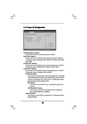
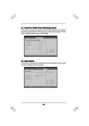
... fan speed, and the critical voltage. MAXTOR 6L08] [CD / DVD] [USB] Configure Settings during System Boot. Main Advanced BIOS SETUP UTILITY H/W Monitor Boot Security Exit Boot Settings Boot Settings Configuration 1st Boot Device 2nd Boot Device 3rd Boot Device 4th Boot Device... Hard Disk Drives Removable Drives [1st Floppy Device] [HDD: PM - BIOS SETUP UTILITY Main Advanced H/W Monitor Boot Security Exit Hardware Health Event Monitoring CPU Temperature M / B Temperature CPU Fan Speed Chassis Fan Speed ...
... fan speed, and the critical voltage. MAXTOR 6L08] [CD / DVD] [USB] Configure Settings during System Boot. Main Advanced BIOS SETUP UTILITY H/W Monitor Boot Security Exit Boot Settings Boot Settings Configuration 1st Boot Device 2nd Boot Device 3rd Boot Device 4th Boot Device... Hard Disk Drives Removable Drives [1st Floppy Device] [HDD: PM - BIOS SETUP UTILITY Main Advanced H/W Monitor Boot Security Exit Hardware Health Event Monitoring CPU Temperature M / B Temperature CPU Fan Speed Chassis Fan Speed ...
User Manual
Page 42
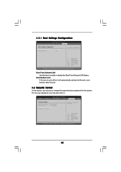
... boot-up. 3.6 Security Screen In this item is set or change the supervisor/user password for the system. 3.5.1 Boot Settings Configuration BIOS SETUP UTILITY Boot Boot Settings Configuration Boot From Onboard LAN Bootup Num-Lock [Disabled] [On] To enable or disable the boot from...Megatrends, Inc. Boot Up Num-Lock If this section, you may set to enable or disable the Boot From Onboard LAN feature. BIOS SETUP UTILITY Main Advanced H/W Monitor Boot Security Exit Security Settings Supervisor Password : Not Installed User Password : Not Installed Change Supervisor Password...
... boot-up. 3.6 Security Screen In this item is set or change the supervisor/user password for the system. 3.5.1 Boot Settings Configuration BIOS SETUP UTILITY Boot Boot Settings Configuration Boot From Onboard LAN Bootup Num-Lock [Disabled] [On] To enable or disable the boot from...Megatrends, Inc. Boot Up Num-Lock If this section, you may set to enable or disable the Boot From Onboard LAN feature. BIOS SETUP UTILITY Main Advanced H/W Monitor Boot Security Exit Security Settings Supervisor Password : Not Installed User Password : Not Installed Change Supervisor Password...


