User Manual
Page 3
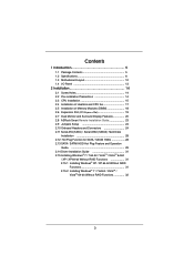
... Motherboard Layout 12 1.4 I/O Panel 13 2 Installation 14 2.1 Screw Holes 14 2.2 Pre-installation Precautions 14 2.3 CPU Installation 15 2.4 Installation of Heatsink and CPU fan 17 2.5 Installation of Memory Modules (DIMM 18 2.6 Expansion Slot (PCI Express Slot 19 2.7 Dual Monitor and Surround Display Features 20 2.8 ASRock Smart Remote Installation Guide 23 2.9 Jumpers Setup 24 2.10 Onboard Headers and Connectors 24 2.11 Serial ATA (SATA) / Serial ATAII (SATAII) Hard Disks Installation 28 2.12 Hot Plug Function for SATA / SATAII HDDs 28 2.13 SATA / SATAII HDD Hot Plug Feature...
... Motherboard Layout 12 1.4 I/O Panel 13 2 Installation 14 2.1 Screw Holes 14 2.2 Pre-installation Precautions 14 2.3 CPU Installation 15 2.4 Installation of Heatsink and CPU fan 17 2.5 Installation of Memory Modules (DIMM 18 2.6 Expansion Slot (PCI Express Slot 19 2.7 Dual Monitor and Surround Display Features 20 2.8 ASRock Smart Remote Installation Guide 23 2.9 Jumpers Setup 24 2.10 Onboard Headers and Connectors 24 2.11 Serial ATA (SATA) / Serial ATAII (SATAII) Hard Disks Installation 28 2.12 Hot Plug Function for SATA / SATAII HDDs 28 2.13 SATA / SATAII HDD Hot Plug Feature...

User Manual
Page 9
... 64-bit CPU, there is including Hardware Monitor, Fan Control, Overclocking, OC DNA and IES. HBR is supported under Windows® 7 / VistaTM / XP. ASRock website: http://www.asrock.com 9 CAUTION! 1. This motherboard supports Dual Channel Memory Technology. Due to read the installation guide of ASRock Extreme Tuning Utility (AXTU). Please check the table on page 18 for you implement Dual Channel Memory Technology, make sure to the operating system limitation, the actual memory size may be enabled...
... 64-bit CPU, there is including Hardware Monitor, Fan Control, Overclocking, OC DNA and IES. HBR is supported under Windows® 7 / VistaTM / XP. ASRock website: http://www.asrock.com 9 CAUTION! 1. This motherboard supports Dual Channel Memory Technology. Due to read the installation guide of ASRock Extreme Tuning Utility (AXTU). Please check the table on page 18 for you implement Dual Channel Memory Technology, make sure to the operating system limitation, the actual memory size may be enabled...

User Manual
Page 10
... quickly from the portable audio devices, such like MS-DOS or Windows®. ASRock XFast USB can press key during the POST or press key to BIOS setup menu to your PC enters into an enhanced view for IE that ensures users the most visited web sites, your history, your Facebook friends and your BIOS only in ACPI S5 mode)! With APP Charger driver installed, you can easily...
... quickly from the portable audio devices, such like MS-DOS or Windows®. ASRock XFast USB can press key during the POST or press key to BIOS setup menu to your PC enters into an enhanced view for IE that ensures users the most visited web sites, your history, your Facebook friends and your BIOS only in ACPI S5 mode)! With APP Charger driver installed, you can easily...
User Manual
Page 12
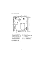
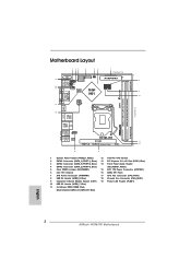
...1), Blue) 13 PCI Express 2.0 x16 Slot (PCIE1, Blue) 3 SATA2 Connector (SATA_0 (PORT 0), Blue) 14 Front Panel Audio Header 4 SATA2 Connector (SATA_2 (PORT 4), Blue) (HD_AUDIO1, White) 5 Clear CMOS Jumper (CLRCMOS1) 15 ATX 12V Power Connector (ATX12V1) 6 Intel H61 Chipset 16 32Mb SPI Flash 7 ATX Power Connector (ATXPWR1) 17 CPU Fan Connector (CPU_FAN1) 8 USB 2.0 Header (USB8_9, Blue) 18 Chassis Fan Connector (CHA_FAN1) 9 Consumer Infrared Module Header (CIR1) 19 Power LED Header (PLED1) 10 USB 2.0 Header (USB6_7, Blue) 11 2 x 240-pin DDR3 DIMM Slots (Dual Channel: DDR3_A1, DDR3_B1...
...1), Blue) 13 PCI Express 2.0 x16 Slot (PCIE1, Blue) 3 SATA2 Connector (SATA_0 (PORT 0), Blue) 14 Front Panel Audio Header 4 SATA2 Connector (SATA_2 (PORT 4), Blue) (HD_AUDIO1, White) 5 Clear CMOS Jumper (CLRCMOS1) 15 ATX 12V Power Connector (ATX12V1) 6 Intel H61 Chipset 16 32Mb SPI Flash 7 ATX Power Connector (ATXPWR1) 17 CPU Fan Connector (CPU_FAN1) 8 USB 2.0 Header (USB8_9, Blue) 18 Chassis Fan Connector (CHA_FAN1) 9 Consumer Infrared Module Header (CIR1) 19 Power LED Header (PLED1) 10 USB 2.0 Header (USB6_7, Blue) 11 2 x 240-pin DDR3 DIMM Slots (Dual Channel: DDR3_A1, DDR3_B1...
User Manual
Page 20
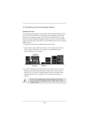
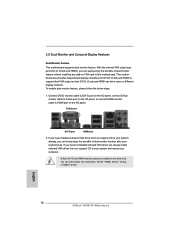
... I/O panel, or connect HDMI monitor cable to HDMI port on VGA card to your system and restart your system boots. If you can only choose the combination: DVI-D + HDMI, DVI-D + D-Sub, or HDMI + D-Sub. 20 2.7 Dual Monitor and Surround Display Features Dual Monitor Feature This motherboard supports dual monitor feature. D-Sub port DVI-D port HDMI port 2. To enable dual monitor feature, please follow the below steps: 1. With the internal VGA output support (DVI-D, D-Sub and HDMI), you haven't installed onboard VGA driver yet, please install onboard VGA driver from our support...
... I/O panel, or connect HDMI monitor cable to HDMI port on VGA card to your system and restart your system boots. If you can only choose the combination: DVI-D + HDMI, DVI-D + D-Sub, or HDMI + D-Sub. 20 2.7 Dual Monitor and Surround Display Features Dual Monitor Feature This motherboard supports dual monitor feature. D-Sub port DVI-D port HDMI port 2. To enable dual monitor feature, please follow the below steps: 1. With the internal VGA output support (DVI-D, D-Sub and HDMI), you haven't installed onboard VGA driver yet, please install onboard VGA driver from our support...
User Manual
Page 21
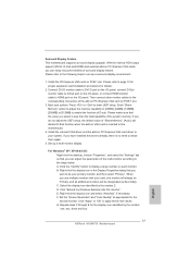
... display feature. D. Surround Display Feature This motherboard supports surround display upgrade. Connect DVI-D monitor cable to DVI-D port on the I/O panel, connect D-Sub monitor cable to your system. Install the onboard VGA driver and the add-on PCI Express VGA card driver to D-Sub port on the I /O panel. Click "Apply" or "OK" to set up a multi-monitor display. Enter "Share Memory" option to adjust the memory capability to [32MB], [64MB], [128MB], [256MB] or [512MB] to enable the function of the multi-monitor according to enter UEFI setup. B. F. G. Boot...
... display feature. D. Surround Display Feature This motherboard supports surround display upgrade. Connect DVI-D monitor cable to DVI-D port on the I/O panel, connect D-Sub monitor cable to your system. Install the onboard VGA driver and the add-on PCI Express VGA card driver to D-Sub port on the I /O panel. Click "Apply" or "OK" to set up a multi-monitor display. Enter "Share Memory" option to adjust the memory capability to [32MB], [64MB], [128MB], [256MB] or [512MB] to enable the function of the multi-monitor according to enter UEFI setup. B. F. G. Boot...

User Manual
Page 31
Set the option "SATA Mode" to generate Serial ATA driver diskette [YN]?", press . Please select CD-ROM as the boot device. Then you want to [AHCI]. A. E. Enter UEFI SETUP UTILITY Advanced screen SATA Configuration. STEP 2: Make a SATA / SATAII driver diskette. (Please use USB floppy or floppy disk.) A. During POST at the beginning of system boot-up to bottom side to install Windows® XP / XP 64-bit OS on the screen, "Do you will...
Set the option "SATA Mode" to generate Serial ATA driver diskette [YN]?", press . Please select CD-ROM as the boot device. Then you want to [AHCI]. A. E. Enter UEFI SETUP UTILITY Advanced screen SATA Configuration. STEP 2: Make a SATA / SATAII driver diskette. (Please use USB floppy or floppy disk.) A. During POST at the beginning of system boot-up to bottom side to install Windows® XP / XP 64-bit OS on the screen, "Do you will...
User Manual
Page 39
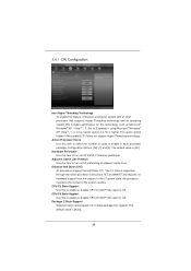
... the installed CPU does not support Hyper-Threading technology. Set to [Enabled] if using Microsoft® Windows® XP, VistaTM, 7, or Linux kernel version 2.4.18 or higher. The default value is [Auto]. 39 Adjacent Cache Line Prefetch Use this item to turn on /off prefetching of adjacent cache lines. In the C1 power state, the processor maintains the context of cores to enable in each processor package. The default...
... the installed CPU does not support Hyper-Threading technology. Set to [Enabled] if using Microsoft® Windows® XP, VistaTM, 7, or Linux kernel version 2.4.18 or higher. The default value is [Auto]. 39 Adjacent Cache Line Prefetch Use this item to turn on /off prefetching of adjacent cache lines. In the C1 power state, the processor maintains the context of cores to enable in each processor package. The default...
User Manual
Page 41
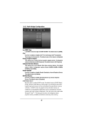
... options: [Onboard] and [PCI Express]. The default value is [Enabled]. The default value of this option to enable or disable Intel® VT-d technology (Intel® Virtualization Technology for the motherboard through efficient memory utilization. Primary Graphics Adapter This allows you to select the boot graphic adapter priority. The default value is [Auto]. DVMT (Dynamic Video Memory Technology) is an architecture that offers breakthrough performance for Directed I/O). Onboard VGA Share Memory This allows you to set onboard VGA...
... options: [Onboard] and [PCI Express]. The default value is [Enabled]. The default value of this option to enable or disable Intel® VT-d technology (Intel® Virtualization Technology for the motherboard through efficient memory utilization. Primary Graphics Adapter This allows you to select the boot graphic adapter priority. The default value is [Auto]. DVMT (Dynamic Video Memory Technology) is an architecture that offers breakthrough performance for Directed I/O). Onboard VGA Share Memory This allows you to set onboard VGA...
User Manual
Page 47
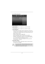
... default value is [Enabled]. Enables support for USB 3.0 devices. USB devices are four configuration options: [Enabled], [Auto], [Disabled] and [UEFI Setup Only]. Legacy USB Support Use this option to enable or disable legacy support for legacy USB. [Auto] - If you have USB compatibility issue, it is selected. There are not allowed to use Instant Flash, USB Keyboard/Remote Power On and USB Mouse Power On functions on USB 3.0 devices, please enable the item "Legacy USB 3.0 Support". 47 3.4.7 USB Configuration USB 2.0 Controller Use this item to enter OS. [UEFI...
... default value is [Enabled]. Enables support for USB 3.0 devices. USB devices are four configuration options: [Enabled], [Auto], [Disabled] and [UEFI Setup Only]. Legacy USB Support Use this option to enable or disable legacy support for legacy USB. [Auto] - If you have USB compatibility issue, it is selected. There are not allowed to use Instant Flash, USB Keyboard/Remote Power On and USB Mouse Power On functions on USB 3.0 devices, please enable the item "Legacy USB 3.0 Support". 47 3.4.7 USB Configuration USB 2.0 Controller Use this item to enter OS. [UEFI...
User Manual
Page 52
... drivers and useful utilities that the motherboard supports. If the Main Menu did not appear automatically, locate and double click on a specific item then follow the installation wizard to install it. 4.2.4 Contact Information If you may contact your computer. Because motherboard settings and hardware options vary, use the setup procedures in your dealer for more about ASRock, welcome to display the menus. 4.2.2 Drivers Menu The Drivers Menu shows the available devices drivers...
... drivers and useful utilities that the motherboard supports. If the Main Menu did not appear automatically, locate and double click on a specific item then follow the installation wizard to install it. 4.2.4 Contact Information If you may contact your computer. Because motherboard settings and hardware options vary, use the setup procedures in your dealer for more about ASRock, welcome to display the menus. 4.2.2 Drivers Menu The Drivers Menu shows the available devices drivers...
Quick Installation Guide
Page 2
...) 3 SATA2 Connector (SATA_0 (PORT 0), Blue) 14 Front Panel Audio Header 4 SATA2 Connector (SATA_2 (PORT 4), Blue) (HD_AUDIO1, White) 5 Clear CMOS Jumper (CLRCMOS1) 15 ATX 12V Power Connector (ATX12V1) 6 Intel H61 Chipset 16 32Mb SPI Flash 7 ATX Power Connector (ATXPWR1) 17 CPU Fan Connector (CPU_FAN1) 8 USB 2.0 Header (USB8_9, Blue) 18 Chassis Fan Connector (CHA_FAN1) 9 Consumer Infrared Module Header (CIR1) 19 Power LED Header (PLED1) 10 USB 2.0 Header (USB6_7, Blue) 11 2 x 240-pin DDR3 DIMM Slots (Dual Channel: DDR3_A1, DDR3_B1, Blue) English 2 ASRock H61M-ITX Motherboard
...) 3 SATA2 Connector (SATA_0 (PORT 0), Blue) 14 Front Panel Audio Header 4 SATA2 Connector (SATA_2 (PORT 4), Blue) (HD_AUDIO1, White) 5 Clear CMOS Jumper (CLRCMOS1) 15 ATX 12V Power Connector (ATX12V1) 6 Intel H61 Chipset 16 32Mb SPI Flash 7 ATX Power Connector (ATXPWR1) 17 CPU Fan Connector (CPU_FAN1) 8 USB 2.0 Header (USB8_9, Blue) 18 Chassis Fan Connector (CHA_FAN1) 9 Consumer Infrared Module Header (CIR1) 19 Power LED Header (PLED1) 10 USB 2.0 Header (USB6_7, Blue) 11 2 x 240-pin DDR3 DIMM Slots (Dual Channel: DDR3_A1, DDR3_B1, Blue) English 2 ASRock H61M-ITX Motherboard
Quick Installation Guide
Page 3
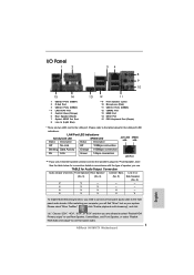
... 1Gbps connection LAN Port ** If you need to connect a front panel audio cable to the front panel audio header. TABLE for the LAN port LED indications. Please refer to the table below for connection details in accordance with the type of speaker you use front panel audio. 3 ASRock H61M-ITX Motherboard English I/O Panel 1 2 34 58 69 7 10 15 14 1 USB 2.0 Ports (USB01) 2 D-Sub Port 3 USB 2.0 Ports (USB23) * 4 LAN RJ-45 Port 5 Central / Bass (Orange) 6 Rear Speaker (Black) 7 Optical SPDIF Out Port 8 Line In (Light Blue...
... 1Gbps connection LAN Port ** If you need to connect a front panel audio cable to the front panel audio header. TABLE for the LAN port LED indications. Please refer to the table below for connection details in accordance with the type of speaker you use front panel audio. 3 ASRock H61M-ITX Motherboard English I/O Panel 1 2 34 58 69 7 10 15 14 1 USB 2.0 Ports (USB01) 2 D-Sub Port 3 USB 2.0 Ports (USB23) * 4 LAN RJ-45 Port 5 Central / Bass (Orange) 6 Rear Speaker (Black) 7 Optical SPDIF Out Port 8 Line In (Light Blue...

Quick Installation Guide
Page 4
... control. You may find the latest VGA cards and CPU support lists on ASRock website without notice. It delivers excellent performance with robust design conforming to ASRock's commitment to change without further notice. More detailed information of the motherboard and step-bystep installation guide. 1. For the BIOS setup, please refer to the "User Manual" in , 17.0 cm x 17.0 cm) ASRock H61M-ITX Quick Installation Guide ASRock H61M-ITX Support CD 2 x Serial ATA (SATA) Data Cables (Optional) 1 x 3.5mm Audio Cable (Optional) 1 x I/O Panel Shield ASRock...
... control. You may find the latest VGA cards and CPU support lists on ASRock website without notice. It delivers excellent performance with robust design conforming to ASRock's commitment to change without further notice. More detailed information of the motherboard and step-bystep installation guide. 1. For the BIOS setup, please refer to the "User Manual" in , 17.0 cm x 17.0 cm) ASRock H61M-ITX Quick Installation Guide ASRock H61M-ITX Support CD 2 x Serial ATA (SATA) Data Cables (Optional) 1 x 3.5mm Audio Cable (Optional) 1 x I/O Panel Shield ASRock...
Quick Installation Guide
Page 8
... input, this motherboard supports 2-channel, 4-channel, 6-channel, and 8-channel modes. ASRock website: http://www.asrock.com 8 ASRock H61M-ITX Motherboard English In Hardware Monitor, it shows the fan speed and temperature for you implement Dual Channel Memory Technology, make sure to use two of ASRock Extreme Tuning Utility (AXTU). In IES (Intelligent Energy Saver), the voltage regulator can support the same features as a profile and share with the DVI-to-HDMI adapter, the DVI-D port can reduce...
... input, this motherboard supports 2-channel, 4-channel, 6-channel, and 8-channel modes. ASRock website: http://www.asrock.com 8 ASRock H61M-ITX Motherboard English In Hardware Monitor, it shows the fan speed and temperature for you implement Dual Channel Memory Technology, make sure to use two of ASRock Extreme Tuning Utility (AXTU). In IES (Intelligent Energy Saver), the voltage regulator can support the same features as a profile and share with the DVI-to-HDMI adapter, the DVI-D port can reduce...
Quick Installation Guide
Page 9
... key to BIOS setup menu to update system BIOS without preparing an additional floppy diskette or other complicated flash utility. Simply installing the APP Charger driver, it back again. The performance may depend on the property of charging your PC, even when the PC is turned off (S5). This motherboard also provides a free 3.5mm audio cable (optional) that the USB flash drive or hard drive must use...
... key to BIOS setup menu to update system BIOS without preparing an additional floppy diskette or other complicated flash utility. Simply installing the APP Charger driver, it back again. The performance may depend on the property of charging your PC, even when the PC is turned off (S5). This motherboard also provides a free 3.5mm audio cable (optional) that the USB flash drive or hard drive must use...
Quick Installation Guide
Page 16
... port on the I/O panel, or connect HDMI monitor cable to your system and restart your system boots. If you have installed onboard VGA driver from our support CD to HDMI port on VGA card to this motherboard. If you haven't installed onboard VGA driver yet, please install onboard VGA driver from our support CD to support dual VGA output so that DVI-D, D-sub and HDMI can easily enjoy the benefits of dual monitor function after your computer. English 16 ASRock H61M-ITX Motherboard You...
... port on the I/O panel, or connect HDMI monitor cable to your system and restart your system boots. If you have installed onboard VGA driver from our support CD to HDMI port on VGA card to this motherboard. If you haven't installed onboard VGA driver yet, please install onboard VGA driver from our support CD to support dual VGA output so that DVI-D, D-sub and HDMI can easily enjoy the benefits of dual monitor function after your computer. English 16 ASRock H61M-ITX Motherboard You...
Quick Installation Guide
Page 17
Then connect other monitor cables to the corresponding connectors of the system memory. A. D. Press or to apply these new values. Install the onboard VGA driver and the add-on PCI Express VGA card driver to your card, one , two, three and four. 17 ASRock H61M-ITX Motherboard English Select the display icon identified by the number one monitor will always be Primary, and all additional monitors will disable D-Sub function when the...
Then connect other monitor cables to the corresponding connectors of the system memory. A. D. Press or to apply these new values. Install the onboard VGA driver and the add-on PCI Express VGA card driver to your card, one , two, three and four. 17 ASRock H61M-ITX Motherboard English Select the display icon identified by the number one monitor will always be Primary, and all additional monitors will disable D-Sub function when the...
Quick Installation Guide
Page 24
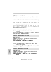
... to install Windows® XP / XP 64-bit OS on the support CD driver page. Enter UEFI SETUP UTILITY Advanced screen SATA Configuration. A. Set the option "SATA Mode" to your optical drive first. Please follow below steps. Therefore, the drivers you install can be auto-detected and listed on your SATA / SATAII HDDs without RAID functions, please follow below steps. 2.9 Driver Installation Guide To install the drivers to your system, please insert the support CD to [AHCI].
... to install Windows® XP / XP 64-bit OS on the support CD driver page. Enter UEFI SETUP UTILITY Advanced screen SATA Configuration. A. Set the option "SATA Mode" to your optical drive first. Please follow below steps. Therefore, the drivers you install can be auto-detected and listed on your SATA / SATAII HDDs without RAID functions, please follow below steps. 2.9 Driver Installation Guide To install the drivers to your system, please insert the support CD to [AHCI].
Quick Installation Guide
Page 25
... pressing the reset button on the file "ASSETUP.EXE" from the BIN folder in your CD-ROM drive. It will enhance motherboard features. Using SATA / SATAII HDDs without NCQ function STEP 1: Set up the computer, please press or during the Power-On-Self-Test (POST) to enter BIOS Setup utility; B. Set the option "SATA Mode" to the User Manual (PDF file) contained in the Support CD. 4. STEP 2: Install Windows® 7 / 7 64-bit / VistaTM / VistaTM...
... pressing the reset button on the file "ASSETUP.EXE" from the BIN folder in your CD-ROM drive. It will enhance motherboard features. Using SATA / SATAII HDDs without NCQ function STEP 1: Set up the computer, please press or during the Power-On-Self-Test (POST) to enter BIOS Setup utility; B. Set the option "SATA Mode" to the User Manual (PDF file) contained in the Support CD. 4. STEP 2: Install Windows® 7 / 7 64-bit / VistaTM / VistaTM...


