User Manual
Page 5
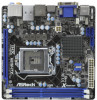
.... To get better performance in Windows® 7 / 7 64-bit / VistaTM / VistaTM 64bit, it is recommended to set the BIOS option in Storage Configuration to the "User Manual" in , 17.0 cm x 17.0 cm) ASRock H61M-ITX Quick Installation Guide ASRock H61M-ITX Support CD 2 x Serial ATA (SATA) Data Cables (Optional) 1 x 3.5mm Audio Cable (Optional) 1 x I/O Panel Shield...
.... To get better performance in Windows® 7 / 7 64-bit / VistaTM / VistaTM 64bit, it is recommended to set the BIOS option in Storage Configuration to the "User Manual" in , 17.0 cm x 17.0 cm) ASRock H61M-ITX Quick Installation Guide ASRock H61M-ITX Support CD 2 x Serial ATA (SATA) Data Cables (Optional) 1 x 3.5mm Audio Cable (Optional) 1 x I/O Panel Shield...
User Manual
Page 7
... 3.0 Ports - 1 x RJ-45 LAN Port with GUI support - HD Audio Jack: Rear Speaker/Central/Bass/Line in/Front Speaker/Microphone (see CAUTION 9) - ASRock Instant Boot - Supports PXE I /O USB 3.0 Connector BIOS Feature Support CD Unique Feature - CPU/Chassis FAN connector - 24 pin ATX power connector - 4 pin 12V power connector - Supports "Plug and Play...
... 3.0 Ports - 1 x RJ-45 LAN Port with GUI support - HD Audio Jack: Rear Speaker/Central/Bass/Line in/Front Speaker/Microphone (see CAUTION 9) - ASRock Instant Boot - Supports PXE I /O USB 3.0 Connector BIOS Feature Support CD Unique Feature - CPU/Chassis FAN connector - 24 pin ATX power connector - 4 pin 12V power connector - Supports "Plug and Play...
User Manual
Page 8
... - FCC, CE, WHQL - We are not responsible for possible damage caused by CPU Temperature) - ASRock U-COP (see CAUTION 11) - CPU Temperature Sensing Monitor - ASRock SmartView (see CAUTION 14) - CPU/Chassis Quiet Fan (Allow Chassis Fan Speed Auto-Adjust by overclocking.... that there is a certain risk involved with overclocking, including adjusting the setting in the BIOS, applying Untied Overclocking Technology, or using the third-party overclocking tools. ASRock On/Off Play Technology (see CAUTION 13) - Chassis Temperature Sensing - Voltage Monitoring: ...
... - FCC, CE, WHQL - We are not responsible for possible damage caused by CPU Temperature) - ASRock U-COP (see CAUTION 11) - CPU Temperature Sensing Monitor - ASRock SmartView (see CAUTION 14) - CPU/Chassis Quiet Fan (Allow Chassis Fan Speed Auto-Adjust by overclocking.... that there is a certain risk involved with overclocking, including adjusting the setting in the BIOS, applying Untied Overclocking Technology, or using the third-party overclocking tools. ASRock On/Off Play Technology (see CAUTION 13) - Chassis Temperature Sensing - Voltage Monitoring: ...

User Manual
Page 10
...bit / VistaTM / VistaTM 64 bit, and your BIOS only in ACPI S5 mode)! 9. ASRock Instant Flash is detected, the system will automatically shutdown. ASRock APP Charger. Simply installing the APP Charger driver, it back again. ASRock APP Charger allows you to quickly charge many Apple ...personal Internet experience. SmartView, a new function of the device. 13. This convenient BIOS update tool allows you - ASRock website: http://www.asrock.com/Feature/AppCharger/index.asp 11. ASRock XFast USB can update your browser version is IE8. To improve heat dissipation, remember...
...bit / VistaTM / VistaTM 64 bit, and your BIOS only in ACPI S5 mode)! 9. ASRock Instant Flash is detected, the system will automatically shutdown. ASRock APP Charger. Simply installing the APP Charger driver, it back again. ASRock APP Charger allows you to quickly charge many Apple ...personal Internet experience. SmartView, a new function of the device. 13. This convenient BIOS update tool allows you - ASRock website: http://www.asrock.com/Feature/AppCharger/index.asp 11. ASRock XFast USB can update your browser version is IE8. To improve heat dissipation, remember...
User Manual
Page 12
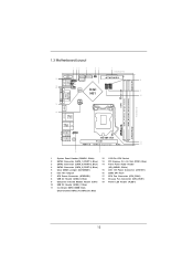
...P W R 1 19 PANEL1 PLED PWRBTN 8 USB 2.0 T: USB0 B: USB1 1 1 HDLED RESET PLED1 CHA_FAN1 SATA_1 (PORT 1) 1 1 1 Gigabit LAN PS2 Keyboard 18 17 CPU_FAN1 32Mb BIOS Intel CIR1 USB6_7 USB8_9 9 H61 10 Fast USB X ATX12V1 DVI_CON1 VGA1 16 17.0cm (6.7 in) DDR3_B1 (64 bit, 240-pin module) ErP/EuP Ready DDR3_A1...USB 2.0 T: USB2 B: USB3 Top: CTR BASS Center: REAR SPK Bottom: Optical SPDIF USB 3.0 T: USB4 Top: B: USB5 RJ-45 HD_AUDIO1 1 H61M-ITX AUDIO CODEC PCIE1 11 HDMI 1.4a USB 3.0 Designed in Taipei RoHS 12 Top: LINE IN Center: FRONT Bottom: MIC IN 14 13 1 System Panel ...
...P W R 1 19 PANEL1 PLED PWRBTN 8 USB 2.0 T: USB0 B: USB1 1 1 HDLED RESET PLED1 CHA_FAN1 SATA_1 (PORT 1) 1 1 1 Gigabit LAN PS2 Keyboard 18 17 CPU_FAN1 32Mb BIOS Intel CIR1 USB6_7 USB8_9 9 H61 10 Fast USB X ATX12V1 DVI_CON1 VGA1 16 17.0cm (6.7 in) DDR3_B1 (64 bit, 240-pin module) ErP/EuP Ready DDR3_A1...USB 2.0 T: USB2 B: USB3 Top: CTR BASS Center: REAR SPK Bottom: Optical SPDIF USB 3.0 T: USB4 Top: B: USB5 RJ-45 HD_AUDIO1 1 H61M-ITX AUDIO CODEC PCIE1 11 HDMI 1.4a USB 3.0 Designed in Taipei RoHS 12 Top: LINE IN Center: FRONT Bottom: MIC IN 14 13 1 System Panel ...
User Manual
Page 24
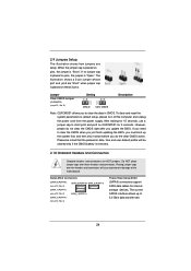
... is placed on CLRCMOS1 for 5 seconds. To clear and reset the system parameters to clear the CMOS when you just finish updating the BIOS, you do not clear the CMOS right after you to 3.0 Gb/s data transfer rate. 24 Jumper Clear CMOS Jumper (CLRCMOS1) (see p.12... (PORT 1): see p.12, No. 2) SATA_1 (PORT 1) (SATA_2 (PORT 4): see p.12, No. 5) Setting Default Clear CMOS Description Note: CLRCMOS1 allows you update the BIOS. If no jumper cap is removed. 2.10 Onboard Headers and Connectors Onboard headers and connectors are setup. Do NOT place jumper caps over the headers...
... is placed on CLRCMOS1 for 5 seconds. To clear and reset the system parameters to clear the CMOS when you just finish updating the BIOS, you do not clear the CMOS right after you to 3.0 Gb/s data transfer rate. 24 Jumper Clear CMOS Jumper (CLRCMOS1) (see p.12... (PORT 1): see p.12, No. 2) SATA_1 (PORT 1) (SATA_2 (PORT 4): see p.12, No. 5) Setting Default Clear CMOS Description Note: CLRCMOS1 allows you update the BIOS. If no jumper cap is removed. 2.10 Onboard Headers and Connectors Onboard headers and connectors are setup. Do NOT place jumper caps over the headers...

User Manual
Page 53
...;: http://support.microsoft.com/kb/979903 53 Start Windows® installation. 5. Set AHCI Mode in UEFI Setup Utility > Boot > Boot Option #1. ("xxx" is adopting UEFI BIOS that allows Windows® OS to launch boot menu at system POST. Choose the item "UEFI:xxx" to boot. 4. If you install Windows® 7 64...
...;: http://support.microsoft.com/kb/979903 53 Start Windows® installation. 5. Set AHCI Mode in UEFI Setup Utility > Boot > Boot Option #1. ("xxx" is adopting UEFI BIOS that allows Windows® OS to launch boot menu at system POST. Choose the item "UEFI:xxx" to boot. 4. If you install Windows® 7 64...
Quick Installation Guide
Page 2
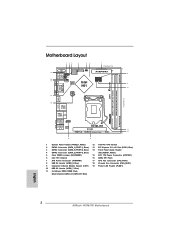
...USB 2.0 T: USB0 B: USB1 1 1 HDLED RESET PLED1 CHA_FAN1 SATA_1 (PORT 1) 1 1 1 Gigabit LAN PS2 Keyboard 18 17 CPU_FAN1 32Mb BIOS Intel CIR1 USB6_7 USB8_9 9 H61 10 Fast USB X ATX12V1 DVI_CON1 VGA1 16 17.0cm (6.7 in) DDR3_B1 (64 bit, 240-pin module) ErP...Top: CTR BASS Center: REAR SPK Bottom: Optical SPDIF USB 3.0 T: USB4 Top: B: USB5 RJ-45 HD_AUDIO1 1 H61M-ITX AUDIO CODEC PCIE1 11 HDMI 1.4a USB 3.0 Designed in Taipei RoHS 12 Top: LINE IN Center: FRONT Bottom: MIC ...2 x 240-pin DDR3 DIMM Slots (Dual Channel: DDR3_A1, DDR3_B1, Blue) English 2 ASRock H61M-ITX Motherboard
...USB 2.0 T: USB0 B: USB1 1 1 HDLED RESET PLED1 CHA_FAN1 SATA_1 (PORT 1) 1 1 1 Gigabit LAN PS2 Keyboard 18 17 CPU_FAN1 32Mb BIOS Intel CIR1 USB6_7 USB8_9 9 H61 10 Fast USB X ATX12V1 DVI_CON1 VGA1 16 17.0cm (6.7 in) DDR3_B1 (64 bit, 240-pin module) ErP...Top: CTR BASS Center: REAR SPK Bottom: Optical SPDIF USB 3.0 T: USB4 Top: B: USB5 RJ-45 HD_AUDIO1 1 H61M-ITX AUDIO CODEC PCIE1 11 HDMI 1.4a USB 3.0 Designed in Taipei RoHS 12 Top: LINE IN Center: FRONT Bottom: MIC ...2 x 240-pin DDR3 DIMM Slots (Dual Channel: DDR3_A1, DDR3_B1, Blue) English 2 ASRock H61M-ITX Motherboard

Quick Installation Guide
Page 4
... 64bit, it is recommended to AHCI mode. ASRock website http://www.asrock.com If you are using. www.asrock.com/support/index.asp 1.1 Package Contents ASRock H61M-ITX Motherboard (Mini-ITX Form Factor: 6.7-in x 6.7-in Storage Configuration to set the BIOS option in , 17.0 cm x 17.0 cm) ASRock H61M-ITX Quick Installation Guide ASRock H61M-ITX Support CD 2 x Serial ATA (SATA) Data...
... 64bit, it is recommended to AHCI mode. ASRock website http://www.asrock.com If you are using. www.asrock.com/support/index.asp 1.1 Package Contents ASRock H61M-ITX Motherboard (Mini-ITX Form Factor: 6.7-in x 6.7-in Storage Configuration to set the BIOS option in , 17.0 cm x 17.0 cm) ASRock H61M-ITX Quick Installation Guide ASRock H61M-ITX Support CD 2 x Serial ATA (SATA) Data...

Quick Installation Guide
Page 6
...ASRock H61M-ITX Motherboard Supports "Plug and Play" - ACPI 1.1 Compliance Wake Up Events - ASRock APP Charger (see CAUTION 7) - 2 x USB 3.0 ports by ASMedia ASM1042, support USB 1.0/2.0/3.0 up to -Use USB 3.0 Ports - 1 x RJ-45 LAN Port with GUI support - Supports PXE I /O USB 3.0 Connector BIOS... Feature Support CD Unique Feature - SMBIOS 2.3.1 Support - ASRock Instant Flash (see CAUTION 8) - CPU/Chassis FAN connector - 24 pin ATX power connector - 4 pin 12V power connector ...
...ASRock H61M-ITX Motherboard Supports "Plug and Play" - ACPI 1.1 Compliance Wake Up Events - ASRock APP Charger (see CAUTION 7) - 2 x USB 3.0 ports by ASMedia ASM1042, support USB 1.0/2.0/3.0 up to -Use USB 3.0 Ports - 1 x RJ-45 LAN Port with GUI support - Supports PXE I /O USB 3.0 Connector BIOS... Feature Support CD Unique Feature - SMBIOS 2.3.1 Support - ASRock Instant Flash (see CAUTION 8) - CPU/Chassis FAN connector - 24 pin ATX power connector - 4 pin 12V power connector ...
Quick Installation Guide
Page 7
... 12) - Boot Failure Guard (B.F.G.) - Voltage Monitoring: +12V, +5V, +3.3V, CPU Vcore OS - English 7 ASRock H61M-ITX Motherboard Hybrid Booster: - Good Night LED Hardware - CPU/Chassis Fan Multi-Speed Control - We are not responsible for possible... CAUTION 15) * For detailed product information, please visit our website: http://www.asrock.com WARNING Please realize that there is a certain risk involved with overclocking, including adjusting the setting in the BIOS, applying Untied Overclocking Technology, or using the third-party overclocking tools. Chassis Temperature ...
... 12) - Boot Failure Guard (B.F.G.) - Voltage Monitoring: +12V, +5V, +3.3V, CPU Vcore OS - English 7 ASRock H61M-ITX Motherboard Hybrid Booster: - Good Night LED Hardware - CPU/Chassis Fan Multi-Speed Control - We are not responsible for possible... CAUTION 15) * For detailed product information, please visit our website: http://www.asrock.com WARNING Please realize that there is a certain risk involved with overclocking, including adjusting the setting in the BIOS, applying Untied Overclocking Technology, or using the third-party overclocking tools. Chassis Temperature ...
Quick Installation Guide
Page 9
... a few clicks without entering operating systems first like MP3 player or mobile phone to update system BIOS without preparing an additional floppy diskette or other complicated flash utility. ASRock website: http://www.asrock.com/Feature/AppCharger/index.asp 11. To use FAT32/16/12 file system. 10. If you... audio devices, such like MS-DOS or Windows®. 9. This motherboard also provides a free 3.5mm audio cable (optional) that helps you install the PC system. 9 ASRock H61M-ITX Motherboard English
... a few clicks without entering operating systems first like MP3 player or mobile phone to update system BIOS without preparing an additional floppy diskette or other complicated flash utility. ASRock website: http://www.asrock.com/Feature/AppCharger/index.asp 11. To use FAT32/16/12 file system. 10. If you... audio devices, such like MS-DOS or Windows®. 9. This motherboard also provides a free 3.5mm audio cable (optional) that helps you install the PC system. 9 ASRock H61M-ITX Motherboard English
Quick Installation Guide
Page 20
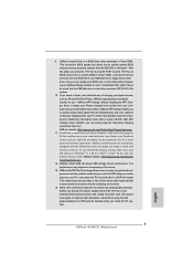
...right after you do the clear-CMOS action. If you need to clear the CMOS when you just finish updating the BIOS, you to short pin2 and pin3 on these headers and connectors. Please be noted that the password, date, time and user... no jumper cap is placed on pins, the jumper is placed on CLRCMOS1 for internal storage devices. Placing jumper caps over these 2 pins. English 20 ASRock H61M-ITX Motherboard Serial ATAII Connectors (SATA_0 (PORT 0): see p.2, No. 3) SATA_0 (PORT 0) SATA_2 (PORT 4) (SATA_1 (PORT 1): see p.2, No. 2) SATA_1 (PORT 1) (SATA_2 (PORT 4): ...
...right after you do the clear-CMOS action. If you need to clear the CMOS when you just finish updating the BIOS, you to short pin2 and pin3 on these headers and connectors. Please be noted that the password, date, time and user... no jumper cap is placed on pins, the jumper is placed on CLRCMOS1 for internal storage devices. Placing jumper caps over these 2 pins. English 20 ASRock H61M-ITX Motherboard Serial ATAII Connectors (SATA_0 (PORT 0): see p.2, No. 3) SATA_0 (PORT 0) SATA_2 (PORT 4) (SATA_1 (PORT 1): see p.2, No. 2) SATA_1 (PORT 1) (SATA_2 (PORT 4): ...
Quick Installation Guide
Page 25
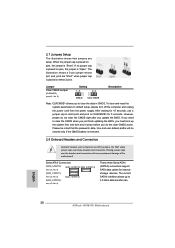
... which allows you start up UEFI. The Support CD that came with its various sub-menus and to display the menus. 25 ASRock H61M-ITX Motherboard English To begin using the Support CD, insert the CD into your computer. A. If the Main Menu does not appear automatically...on the system chassis. STEP 2: Install Windows® 7 / 7 64-bit / VistaTM / VistaTM 64-bit OS on the motherboard stores BIOS Setup Utility. The BIOS Setup program is enabled in the Support CD. 4. Software Support CD information This motherboard supports various Microsoft® Windows® operating systems: 7 ...
... which allows you start up UEFI. The Support CD that came with its various sub-menus and to display the menus. 25 ASRock H61M-ITX Motherboard English To begin using the Support CD, insert the CD into your computer. A. If the Main Menu does not appear automatically...on the system chassis. STEP 2: Install Windows® 7 / 7 64-bit / VistaTM / VistaTM 64-bit OS on the motherboard stores BIOS Setup Utility. The BIOS Setup program is enabled in the Support CD. 4. Software Support CD information This motherboard supports various Microsoft® Windows® operating systems: 7 ...
Quick Installation Guide
Page 107
... - B.F.G..(Boot Failure Guard) - 굿나잇 LED CPU - ErP/EuP 지원 (ErP/EuP ( 주의 15 참조 ) http://www.asrock.com BIOS Untied Overclocking Technology 한 국 어 107 ASRock H61M-ITX Motherboard - ASRock U-COP ( 주의 14 참조 ) - CPU CPU 가능 ) - CPU 12V,+5V,+3.3V,Vcore OS Windows® 7/7 64 비...
... - B.F.G..(Boot Failure Guard) - 굿나잇 LED CPU - ErP/EuP 지원 (ErP/EuP ( 주의 15 참조 ) http://www.asrock.com BIOS Untied Overclocking Technology 한 국 어 107 ASRock H61M-ITX Motherboard - ASRock U-COP ( 주의 14 참조 ) - CPU CPU 가능 ) - CPU 12V,+5V,+3.3V,Vcore OS Windows® 7/7 64 비...
Quick Installation Guide
Page 110
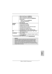
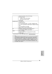
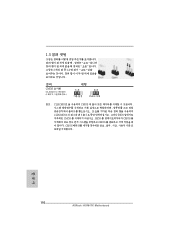
1.3 3 1-2 점퍼 CMOS 초기화 (CLRCMOS1, 3 2 5 세팅 CMOS 삭제 참고 : CLRCMOS1 CMOS 15 CLRCMOS1 의 핀 2 와 핀 3 을 5 BIOS CMOS BIOS CMOS CMOS CMOS 한 국 어 110 ASRock H61M-ITX Motherboard
1.3 3 1-2 점퍼 CMOS 초기화 (CLRCMOS1, 3 2 5 세팅 CMOS 삭제 참고 : CLRCMOS1 CMOS 15 CLRCMOS1 의 핀 2 와 핀 3 을 5 BIOS CMOS BIOS CMOS CMOS CMOS 한 국 어 110 ASRock H61M-ITX Motherboard
Quick Installation Guide
Page 119
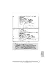
... OS - ASRock XFast USB ( 注意 12 を参照 ) - ASRock U-COP ( 注意 14 を参照 ) Boot Failure Guard:B.F.G.) LED モニター - FCC, CE, Microsoft® WHQL - ErP/EuP 対応(ErP/EuP ( 注意 15 を参照 ) http://www.asrock.com BIOS 日本語 119 ASRock H61M-ITX Motherboard
... OS - ASRock XFast USB ( 注意 12 を参照 ) - ASRock U-COP ( 注意 14 を参照 ) Boot Failure Guard:B.F.G.) LED モニター - FCC, CE, Microsoft® WHQL - ErP/EuP 対応(ErP/EuP ( 注意 15 を参照 ) http://www.asrock.com BIOS 日本語 119 ASRock H61M-ITX Motherboard
Quick Installation Guide
Page 123
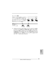
1.3 1-2 CMOS CLRCMOS1 5 参照) 設定 説明 CMOS の消去 注 : CLRCMOS1 CMOS 15 CLRCMOS1 のピン 2 とピン 3 を 5 BIOS CMOS BIOS CMOS CMOS CMOS 日本語 123 ASRock H61M-ITX Motherboard
1.3 1-2 CMOS CLRCMOS1 5 参照) 設定 説明 CMOS の消去 注 : CLRCMOS1 CMOS 15 CLRCMOS1 のピン 2 とピン 3 を 5 BIOS CMOS BIOS CMOS CMOS CMOS 日本語 123 ASRock H61M-ITX Motherboard
Quick Installation Guide
Page 132
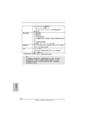
Boot Failure Guard (B.F.G - ASRock U-COP 14) - CPU - CPU - CPU CPU 度) - CPU 12V, +5V, +3.3V 操作系統 - Hybrid Booster - Microsoft® Windows® 7/7 64 位元 /VistaTM/VistaTM 64 位元 / XP/XP 64 認證 - FCC, CE, WHQL - 支持 ErP/EuP ErP/EuP 15) http://www.asrock.com BIOS 簡體中文 132 ASRock H61M-ITX Motherboard -
Boot Failure Guard (B.F.G - ASRock U-COP 14) - CPU - CPU - CPU CPU 度) - CPU 12V, +5V, +3.3V 操作系統 - Hybrid Booster - Microsoft® Windows® 7/7 64 位元 /VistaTM/VistaTM 64 位元 / XP/XP 64 認證 - FCC, CE, WHQL - 支持 ErP/EuP ErP/EuP 15) http://www.asrock.com BIOS 簡體中文 132 ASRock H61M-ITX Motherboard -
Quick Installation Guide
Page 139
BIOS 信息 Flash Memory 存儲了 BIOS POST F2> 或 < D e l B I O S P O S T P O S T B I O S Ctrl>++ 2.
BIOS 信息 Flash Memory 存儲了 BIOS POST F2> 或 < D e l B I O S P O S T P O S T B I O S Ctrl>++ 2.


