
User Manual
Page 1
H61M-ITX User Manual Version 1.0 Published May 2011 Copyright©2011 ASRock INC. All rights reserved. 1
H61M-ITX User Manual Version 1.0 Published May 2011 Copyright©2011 ASRock INC. All rights reserved. 1

User Manual
Page 2
...may apply, see www.dtsc.ca.gov/hazardouswaste/perchlorate" ASRock Website: http://www.asrock.com 2 Disclaimer: Specifications and information contained in this manual are used only for backup purpose, without written consent of ASRock Inc. In no responsibility for informational use only and... Lithium battery adopted on this motherboard contains Perchlorate, a toxic substance controlled in advance. With respect to the contents of this manual, ASRock does not provide warranty of any kind, either expressed or implied, including but not limited to the implied warranties or conditions ...
...may apply, see www.dtsc.ca.gov/hazardouswaste/perchlorate" ASRock Website: http://www.asrock.com 2 Disclaimer: Specifications and information contained in this manual are used only for backup purpose, without written consent of ASRock Inc. In no responsibility for informational use only and... Lithium battery adopted on this motherboard contains Perchlorate, a toxic substance controlled in advance. With respect to the contents of this manual, ASRock does not provide warranty of any kind, either expressed or implied, including but not limited to the implied warranties or conditions ...
User Manual
Page 5
... find the latest VGA cards and CPU support lists on ASRock website without notice. Chapter 3 and 4 contain the configuration guide to the "User Manual" in , 17.0 cm x 17.0 cm) ASRock H61M-ITX Quick Installation Guide ASRock H61M-ITX Support CD 2 x Serial ATA (SATA) Data Cables (Optional)... 1 x 3.5mm Audio Cable (Optional) 1 x I/O Panel Shield ASRock Reminds You... For the BIOS setup, please...
... find the latest VGA cards and CPU support lists on ASRock website without notice. Chapter 3 and 4 contain the configuration guide to the "User Manual" in , 17.0 cm x 17.0 cm) ASRock H61M-ITX Quick Installation Guide ASRock H61M-ITX Support CD 2 x Serial ATA (SATA) Data Cables (Optional)... 1 x 3.5mm Audio Cable (Optional) 1 x I/O Panel Shield ASRock Reminds You... For the BIOS setup, please...

User Manual
Page 17
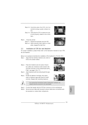
... page 12, No. 17). Connect fan header with 1155-Pin socket that the CPU and the heatsink are oriented on side closest to the instruction manuals of your CPU fan and heatsink.
... page 12, No. 17). Connect fan header with 1155-Pin socket that the CPU and the heatsink are oriented on side closest to the instruction manuals of your CPU fan and heatsink.

User Manual
Page 26
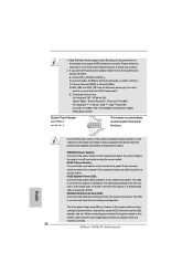
... : A. You may differ by chassis. RESET (Reset Switch): Connect to turn off (S5). The LED is on when the hard drive is in our manual and chassis manual to function correctly. The LED keeps blinking when the system is reading or writing data. HDLED (Hard Drive Activity LED): Connect to this header...
... : A. You may differ by chassis. RESET (Reset Switch): Connect to turn off (S5). The LED is on when the hard drive is in our manual and chassis manual to function correctly. The LED keeps blinking when the system is reading or writing data. HDLED (Hard Drive Activity LED): Connect to this header...
User Manual
Page 29
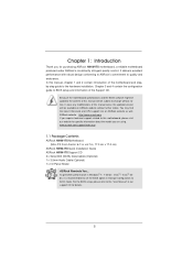
... SATA / SATAII Hot Plug cannot be damaged under the Hot Plug operation. 3. Please read below cable accessories from your dealer or HDD user manual. SATA data cable (Red) B. Points of Hot Plug feature carefully. The latest SATA / SATAII driver is installed into system properly. Before you... IDE 1x4-pin conventional power connector interface is designed only for SATA / SATAII HDD in the product spec on our support website: www.asrock.com 4. 2.13 SATA / SATAII HDD Hot Plug Feature and Operation Guide This motherboard supports Hot Plug feature for our motherboard, which cannot...
... SATA / SATAII Hot Plug cannot be damaged under the Hot Plug operation. 3. Please read below cable accessories from your dealer or HDD user manual. SATA data cable (Red) B. Points of Hot Plug feature carefully. The latest SATA / SATAII driver is installed into system properly. Before you... IDE 1x4-pin conventional power connector interface is designed only for SATA / SATAII HDD in the product spec on our support website: www.asrock.com 4. 2.13 SATA / SATAII HDD Hot Plug Feature and Operation Guide This motherboard supports Hot Plug feature for our motherboard, which cannot...

User Manual
Page 36
.... Write Recovery Time (tWR) Use this item to change Write Recovery Time (tWR) Auto/Manual setting. RAS to RAS Delay (tRRD) Use this item to change RAS to Precharge (tRTP) Auto/Manual setting. The default is [Auto]. Refresh Cyle Time (tRFC) Use this item to change Row...selected, the motherboard will detect the memory module(s) inserted and assigns appropriate frequency automatically for DDR3 1333 memory module(s), please manually adjust it to CAS# Delay (tRCD) Auto/Manual setting. The default is [Auto]. CAS# Latency (tCL) Use this item to change Command Rate (CR) Auto...
.... Write Recovery Time (tWR) Use this item to change Write Recovery Time (tWR) Auto/Manual setting. RAS to RAS Delay (tRRD) Use this item to change RAS to Precharge (tRTP) Auto/Manual setting. The default is [Auto]. Refresh Cyle Time (tRFC) Use this item to change Row...selected, the motherboard will detect the memory module(s) inserted and assigns appropriate frequency automatically for DDR3 1333 memory module(s), please manually adjust it to CAS# Delay (tRCD) Auto/Manual setting. The default is [Auto]. CAS# Latency (tCL) Use this item to change Command Rate (CR) Auto...

User Manual
Page 37
Memory Power Down Mode Use this item to your own requirements. 37 The default value is [Auto]. User Default In this option, you are allowed to load and save three user defaults according to adjust DDR power down mode. Configuration options: [Auto], [Slow] and [Fast]. Four Activate Window (tFAW) Use this item to select DRAM Voltage. Voltage Control DRAM Voltage Use this to change Four Activate Window (tFAW) Auto/Manual setting. The default is [Auto]. The default value is [Auto].
Memory Power Down Mode Use this item to your own requirements. 37 The default value is [Auto]. User Default In this option, you are allowed to load and save three user defaults according to adjust DDR power down mode. Configuration options: [Auto], [Slow] and [Fast]. Four Activate Window (tFAW) Use this item to select DRAM Voltage. Voltage Control DRAM Voltage Use this to change Four Activate Window (tFAW) Auto/Manual setting. The default is [Auto]. The default value is [Auto].

Quick Installation Guide
Page 4
.... To get better performance in Windows® 7 / 7 64-bit / VistaTM / VistaTM 64bit, it is recommended to the "User Manual" in the Support CD. www.asrock.com/support/index.asp 1.1 Package Contents ASRock H61M-ITX Motherboard (Mini-ITX Form Factor: 6.7-in x 6.7-in Storage Configuration to quality and endurance. 1. Introduction Thank you are using. You may...
.... To get better performance in Windows® 7 / 7 64-bit / VistaTM / VistaTM 64bit, it is recommended to the "User Manual" in the Support CD. www.asrock.com/support/index.asp 1.1 Package Contents ASRock H61M-ITX Motherboard (Mini-ITX Form Factor: 6.7-in x 6.7-in Storage Configuration to quality and endurance. 1. Introduction Thank you are using. You may...
Quick Installation Guide
Page 8
... Tuning Utility (AXTU) is subject to use two of "User Manual" in -one tool to the operating system limitation, the actual memory size may be enabled at the same time. ASRock website: http://www.asrock.com 8 ASRock H61M-ITX Motherboard English The maximum shared memory size is defined by the chipset vendor and is...-D port can choose to change. In Overclocking, you can load the OC profile to their own system to read the installation guide of ASRock Extreme Tuning Utility (AXTU).
... Tuning Utility (AXTU) is subject to use two of "User Manual" in -one tool to the operating system limitation, the actual memory size may be enabled at the same time. ASRock website: http://www.asrock.com 8 ASRock H61M-ITX Motherboard English The maximum shared memory size is defined by the chipset vendor and is...-D port can choose to change. In Overclocking, you can load the OC profile to their own system to read the installation guide of ASRock Extreme Tuning Utility (AXTU).
Quick Installation Guide
Page 13
... down on fastener caps with the CPU fan connector on the motherboard. Connect fan header with thumb to install and lock. English 13 ASRock H61M-ITX Motherboard Carefully place the CPU into the socket by using a purely vertical motion. Step 4-2. Below is within the socket and properly mated...Apply thermal interface material onto center of the heatsink for 1155-Pin CPU. Ensure fan cables are oriented on side closest to the instruction manuals of CPU Fan and Heatsink For proper installation, please kindly refer to the CPU fan connector on the socket surface. Align fasteners with...
... down on fastener caps with the CPU fan connector on the motherboard. Connect fan header with thumb to install and lock. English 13 ASRock H61M-ITX Motherboard Carefully place the CPU into the socket by using a purely vertical motion. Step 4-2. Below is within the socket and properly mated...Apply thermal interface material onto center of the heatsink for 1155-Pin CPU. Ensure fan cables are oriented on side closest to the instruction manuals of CPU Fan and Heatsink For proper installation, please kindly refer to the CPU fan connector on the socket surface. Align fasteners with...
Quick Installation Guide
Page 22
... restart. Press the reset switch to restart the computer if the computer freezes and fails to OUT2_L. MIC_RET and OUT_RET are matched correctly. 22 ASRock H61M-ITX Motherboard English For Windows® XP / XP 64-bit OS: Select "Mixer". Connect the power switch, reset switch and system status indicator ...install your system. 2. The front panel design may configure the way to turn off when the system is in our manual and chassis manual to this header according to the hard drive activity LED on the chassis front panel. D. The LED keeps blinking when the system...
... restart. Press the reset switch to restart the computer if the computer freezes and fails to OUT2_L. MIC_RET and OUT_RET are matched correctly. 22 ASRock H61M-ITX Motherboard English For Windows® XP / XP 64-bit OS: Select "Mixer". Connect the power switch, reset switch and system status indicator ...install your system. 2. The front panel design may configure the way to turn off when the system is in our manual and chassis manual to this header according to the hard drive activity LED on the chassis front panel. D. The LED keeps blinking when the system...
Quick Installation Guide
Page 25
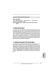
...;le "ASSETUP.EXE" from the BIN folder in the Support CD to the User Manual (PDF file) contained in your computer. For the detailed information about BIOS Setup, please refer to display the menus. 25 ASRock H61M-ITX Motherboard English It will enhance motherboard features. If the Main Menu does not appear automatically...
...;le "ASSETUP.EXE" from the BIN folder in the Support CD to the User Manual (PDF file) contained in your computer. For the detailed information about BIOS Setup, please refer to display the menus. 25 ASRock H61M-ITX Motherboard English It will enhance motherboard features. If the Main Menu does not appear automatically...
Quick Installation Guide
Page 145
警告! 1、 關於"Hyper-Threading Technology CD User Manual 39 頁。 2 14 3 Windows® 7 / VistaTM / XP 4GB。對於 Windows 64 位元 CPU 4 Intel 5 D-Sub...C O C OC IES (Intelligent Energy Saver),當 CPU ASRock Extreme Tuning Utility (AXTU ASRock http://www.asrock.com 9、 華擎 Instant Flash Flash ROM 的 BIOS BIOS MS-DOS 或 Windows BIOS F6 BIOS F2 Instant Flash B I O S B I O S FAT32/64 145 ASRock H61M-ITX Motherboard 繁體中文
警告! 1、 關於"Hyper-Threading Technology CD User Manual 39 頁。 2 14 3 Windows® 7 / VistaTM / XP 4GB。對於 Windows 64 位元 CPU 4 Intel 5 D-Sub...C O C OC IES (Intelligent Energy Saver),當 CPU ASRock Extreme Tuning Utility (AXTU ASRock http://www.asrock.com 9、 華擎 Instant Flash Flash ROM 的 BIOS BIOS MS-DOS 或 Windows BIOS F6 BIOS F2 Instant Flash B I O S B I O S FAT32/64 145 ASRock H61M-ITX Motherboard 繁體中文
