
User Manual
Page 2
Products and corporate names appearing in Perchlorate Best Management Practices (BMP) regulations passed by ASRock. CALIFORNIA, USA ONLY The Lithium battery adopted on this motherboard contains Perchlorate, a toxic substance controlled in this manual may or may not be registered trademarks or ...battery in California, USA, please follow the related regulations in this manual. This device complies with Part 15 of ASRock Inc. ASRock assumes no event shall ASRock, its directors, officers, employees, or agents be liable for any indirect, special, incidental, or consequential ...
Products and corporate names appearing in Perchlorate Best Management Practices (BMP) regulations passed by ASRock. CALIFORNIA, USA ONLY The Lithium battery adopted on this motherboard contains Perchlorate, a toxic substance controlled in this manual may or may not be registered trademarks or ...battery in California, USA, please follow the related regulations in this manual. This device complies with Part 15 of ASRock Inc. ASRock assumes no event shall ASRock, its directors, officers, employees, or agents be liable for any indirect, special, incidental, or consequential ...
User Manual
Page 3
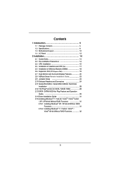
... Contents 5 1.2 Specifications 6 1.3 Motherboard Layout 12 1.4 I/O Panel 13 2 Installation 14 2.1 Screw Holes 14 2.2 Pre-installation Precautions 14 2.3 CPU Installation 15 2.4 Installation of Heatsink and CPU fan 17 2.5 Installation of Memory Modules (DIMM 18 2.6 Expansion Slot (PCI Express Slot 19 2.7 Dual Monitor and Surround Display Features 20 2.8 ASRock Smart Remote Installation Guide...
... Contents 5 1.2 Specifications 6 1.3 Motherboard Layout 12 1.4 I/O Panel 13 2 Installation 14 2.1 Screw Holes 14 2.2 Pre-installation Precautions 14 2.3 CPU Installation 15 2.4 Installation of Heatsink and CPU fan 17 2.5 Installation of Memory Modules (DIMM 18 2.6 Expansion Slot (PCI Express Slot 19 2.7 Dual Monitor and Surround Display Features 20 2.8 ASRock Smart Remote Installation Guide...
User Manual
Page 5
...-bit / VistaTM / VistaTM 64bit, it is recommended to AHCI mode. www.asrock.com/support/index.asp 1.1 Package Contents ASRock H61M-ITX Motherboard (Mini-ITX Form Factor: 6.7-in x 6.7-in Storage Configuration to set the BIOS option in , 17.0 cm x 17.0 cm) ASRock H61M-ITX Quick Installation Guide ASRock H61M-ITX Support CD 2 x Serial ATA (SATA) Data Cables (Optional) 1 x 3.5mm Audio Cable...
...-bit / VistaTM / VistaTM 64bit, it is recommended to AHCI mode. www.asrock.com/support/index.asp 1.1 Package Contents ASRock H61M-ITX Motherboard (Mini-ITX Form Factor: 6.7-in x 6.7-in Storage Configuration to set the BIOS option in , 17.0 cm x 17.0 cm) ASRock H61M-ITX Quick Installation Guide ASRock H61M-ITX Support CD 2 x Serial ATA (SATA) Data Cables (Optional) 1 x 3.5mm Audio Cable...

User Manual
Page 9
...the OC profile to their own system to use two of memory modules on page 13 for the latest information. 5. This motherboard supports Dual Channel Memory Technology. Before you to change. D-Sub, DVI-D and HDMI monitors cannot be less than 4GB for the ...operation procedures of your OC settings as HDMIport. 6. In IES (Intelligent Energy Saver), the voltage regulator can save your system. ASRock website: http://www.asrock.com 9 About the setting of output phases to overclock CPU frequency for optimal system performance. The maximum shared memory size is ...
...the OC profile to their own system to use two of memory modules on page 13 for the latest information. 5. This motherboard supports Dual Channel Memory Technology. Before you to change. D-Sub, DVI-D and HDMI monitors cannot be less than 4GB for the ...operation procedures of your OC settings as HDMIport. 6. In IES (Intelligent Energy Saver), the voltage regulator can save your system. ASRock website: http://www.asrock.com 9 About the setting of output phases to overclock CPU frequency for optimal system performance. The maximum shared memory size is ...

User Manual
Page 10
... version is detected, the system will automatically shutdown. Simply installing the APP Charger driver, it back again. ASRock website: http://www.asrock.com/Feature/ SmartView/index.asp 12. This motherboard also provides a free 3.5mm audio cable (optional) that helps you keep in Flash ROM. To improve heat...experience from your BIOS only in ACPI S5 mode)! Please be noted that combines your most convenient computing environment. 14. ASRock motherboards are exclusively equipped with friends on-the-go. To use FAT32/16/12 file system. 10. The performance may depend on ...
... version is detected, the system will automatically shutdown. Simply installing the APP Charger driver, it back again. ASRock website: http://www.asrock.com/Feature/ SmartView/index.asp 12. This motherboard also provides a free 3.5mm audio cable (optional) that helps you keep in Flash ROM. To improve heat...experience from your BIOS only in ACPI S5 mode)! Please be noted that combines your most convenient computing environment. 14. ASRock motherboards are exclusively equipped with friends on-the-go. To use FAT32/16/12 file system. 10. The performance may depend on ...

User Manual
Page 11
... with the power supply manufacturer for the completed system. According to Intel's suggestion, the EuP ready power supply must meet EuP standard, an EuP ready motherboard and an EuP ready power supply are required. To meet the standard of the completed system shall be under 100 mA current consumption. According to...
... with the power supply manufacturer for the completed system. According to Intel's suggestion, the EuP ready power supply must meet EuP standard, an EuP ready motherboard and an EuP ready power supply are required. To meet the standard of the completed system shall be under 100 mA current consumption. According to...
User Manual
Page 12
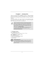
1.3 Motherboard Layout 1 23 4 56 7 17.0cm (6.7 in) SATA_0 (PORT 0) SATA_2 (PORT 4) CMOS 1 Battery CLRCMOS1 AT X P W R 1 19 PANEL1 PLED PWRBTN 8 USB 2.0 T: USB0 B: USB1 1 1 HDLED RESET PLED1 CHA_FAN1 ...-pin module) DDR3 HDMI1 ESATA1 15 USB 2.0 T: USB2 B: USB3 Top: CTR BASS Center: REAR SPK Bottom: Optical SPDIF USB 3.0 T: USB4 Top: B: USB5 RJ-45 HD_AUDIO1 1 H61M-ITX AUDIO CODEC PCIE1 11 HDMI 1.4a USB 3.0 Designed in Taipei RoHS 12 Top: LINE IN Center: FRONT Bottom: MIC IN 14 13 1 System Panel Header...
1.3 Motherboard Layout 1 23 4 56 7 17.0cm (6.7 in) SATA_0 (PORT 0) SATA_2 (PORT 4) CMOS 1 Battery CLRCMOS1 AT X P W R 1 19 PANEL1 PLED PWRBTN 8 USB 2.0 T: USB0 B: USB1 1 1 HDLED RESET PLED1 CHA_FAN1 ...-pin module) DDR3 HDMI1 ESATA1 15 USB 2.0 T: USB2 B: USB3 Top: CTR BASS Center: REAR SPK Bottom: Optical SPDIF USB 3.0 T: USB4 Top: B: USB5 RJ-45 HD_AUDIO1 1 H61M-ITX AUDIO CODEC PCIE1 11 HDMI 1.4a USB 3.0 Designed in Taipei RoHS 12 Top: LINE IN Center: FRONT Bottom: MIC IN 14 13 1 System Panel Header...

User Manual
Page 14
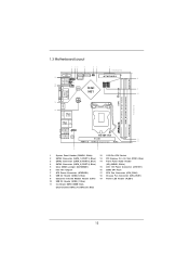
...install the motherboard, study the configuration of the following precautions before you and damages to you install motherboard components or...motherboard. 2.2 Pre-installation Precautions Take note of your motherboard directly on a grounded antistatic pad or in the bag that the motherboard fits into the holes indicated by circles to secure the motherboard to the motherboard...Also remember to unplug the power cord before touching any motherboard settings. 1. Unplug the power cord from the power ...removing the motherboard. Before you uninstall any component, ensure that the power is ...
...install the motherboard, study the configuration of the following precautions before you and damages to you install motherboard components or...motherboard. 2.2 Pre-installation Precautions Take note of your motherboard directly on a grounded antistatic pad or in the bag that the motherboard fits into the holes indicated by circles to secure the motherboard to the motherboard...Also remember to unplug the power cord before touching any motherboard settings. 1. Unplug the power cord from the power ...removing the motherboard. Before you uninstall any component, ensure that the power is ...
User Manual
Page 15
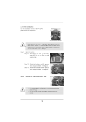
... is any bent pin on the hook to handle and avoid kicking off the PnP cap. 2. Otherwise, the CPU will be placed if returning the motherboard for after service. 15 Rotate the load plate to fully open position at approximately 100 degrees. Do not force to fully open position at approximately...
... is any bent pin on the hook to handle and avoid kicking off the PnP cap. 2. Otherwise, the CPU will be placed if returning the motherboard for after service. 15 Rotate the load plate to fully open position at approximately 100 degrees. Do not force to fully open position at approximately...

User Manual
Page 17
...CPU. Align fasteners with Intel 1155Pin CPU to dissipate heat. Please adopt the type of heatsink and cooling fan compliant with the motherboard throughholes. Apply Thermal Interface Material Step 2. Step 3. Connect fan header with remaining fasteners. Before you installed the heatsink, you ...securely fastened and in good contact with each other components. 17 Step 5. Step 4. Repeat with the CPU fan connector on the motherboard. Secure excess cable with tie-wrap to ensure cable does not interfere with fan operation or contact other . 2.4 Installation of CPU...
...CPU. Align fasteners with Intel 1155Pin CPU to dissipate heat. Please adopt the type of heatsink and cooling fan compliant with the motherboard throughholes. Apply Thermal Interface Material Step 2. Step 3. Connect fan header with remaining fasteners. Before you installed the heatsink, you ...securely fastened and in good contact with each other components. 17 Step 5. Step 4. Repeat with the CPU fan connector on the motherboard. Secure excess cable with tie-wrap to ensure cable does not interfere with fan operation or contact other . 2.4 Installation of CPU...
User Manual
Page 18
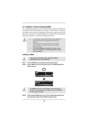
...one correct orientation. It is not recommended to activate the Dual Channel Memory Technology. 3. Step 3. Installing a DIMM Please make sure to the motherboard and the DIMM if you force the DIMM into the slot until the retaining clips at single channel mode. 1. Step 2. notch break notch ...break The DIMM only fits in place and the DIMM is unable to install them on this motherboard. Firmly insert the DIMM into the slot at incorrect orientation. Some DDR3 1GB double-sided DIMMs with 16 chips may be damaged. 2. Align...
...one correct orientation. It is not recommended to activate the Dual Channel Memory Technology. 3. Step 3. Installing a DIMM Please make sure to the motherboard and the DIMM if you force the DIMM into the slot until the retaining clips at single channel mode. 1. Step 2. notch break notch ...break The DIMM only fits in place and the DIMM is unable to install them on this motherboard. Firmly insert the DIMM into the slot at incorrect orientation. Some DDR3 1GB double-sided DIMMs with 16 chips may be damaged. 2. Align...
User Manual
Page 19
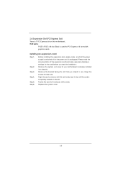
... chassis with the slot and press firmly until the card is already installed in a chassis). Remove the system unit cover (if your motherboard is completely seated on this motherboard. Align the card connector with screws. 2.6 Expansion Slot (PCI Express Slot) There is 1 PCI Express slot on the slot. PCIE slots: PCIE1...
... chassis with the slot and press firmly until the card is already installed in a chassis). Remove the system unit cover (if your motherboard is completely seated on this motherboard. Align the card connector with screws. 2.6 Expansion Slot (PCI Express Slot) There is 1 PCI Express slot on the slot. PCIE slots: PCIE1...
User Manual
Page 20
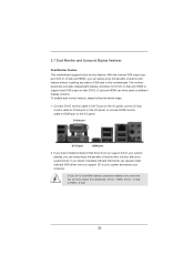
... provides independent display controllers for DVI-D, D-Sub and HDMI to this motherboard. If you haven't installed onboard VGA driver yet, please install onboard VGA driver from our support CD to your system already, you can easily enjoy ... monitor function after your computer. To enable dual monitor feature, please follow the below steps: 1. 2.7 Dual Monitor and Surround Display Features Dual Monitor Feature This motherboard supports dual monitor feature. Connect DVI-D monitor cable to DVI-D port on the I/O panel, connect D-Sub monitor cable to D-Sub port on the I /O panel, or...
... provides independent display controllers for DVI-D, D-Sub and HDMI to this motherboard. If you haven't installed onboard VGA driver yet, please install onboard VGA driver from our support CD to your system already, you can easily enjoy ... monitor function after your computer. To enable dual monitor feature, please follow the below steps: 1. 2.7 Dual Monitor and Surround Display Features Dual Monitor Feature This motherboard supports dual monitor feature. Connect DVI-D monitor cable to DVI-D port on the I/O panel, connect D-Sub monitor cable to D-Sub port on the I /O panel, or...
User Manual
Page 21
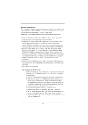
..., or connect HDMI monitor cable to set up a multi-monitor display. Set up a surround display environment: 1. B. Click "Extend my Windows desktop onto this motherboard. 4. Surround Display Feature This motherboard supports surround display upgrade. Please refer to the following steps to HDMI port on PCIE1 slot. Please make sure that the value you...
..., or connect HDMI monitor cable to set up a multi-monitor display. Set up a surround display environment: 1. B. Click "Extend my Windows desktop onto this motherboard. 4. Surround Display Feature This motherboard supports surround display upgrade. Please refer to the following steps to HDMI port on PCIE1 slot. Please make sure that the value you...
User Manual
Page 22
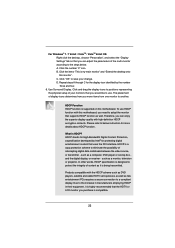
...the multi-monitor according to adopt the monitor that the HDTV or LCD monitor you can enjoy the superior display quality with this motherboard, you need to the steps below instruction for protecting digital entertainment content that you would like to use HDCP function with high-de... it is supported on this monitor". Due to a compliant display. such as it is my main monitor" and "Extend the desktop onto this motherboard. HDCP is HDCP? Click "OK" to another. Therefore, you move items from one monitor to save your monitors that uses the DVI interface....
...the multi-monitor according to adopt the monitor that the HDTV or LCD monitor you can enjoy the superior display quality with this motherboard, you need to the steps below instruction for protecting digital entertainment content that you would like to use HDCP function with high-de... it is supported on this monitor". Due to a compliant display. such as it is my main monitor" and "Extend the desktop onto this motherboard. HDCP is HDCP? Click "OK" to another. Therefore, you move items from one monitor to save your monitors that uses the DVI interface....
User Manual
Page 23
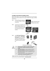
...Find the CIR header located next to the USB 2.0 header on the market. 3. Multi-Angle CIR Receiver is used for ASRock motherboard with most of ASRock motherboards. Please refer to below , pin 1-5) and the CIR header. If Multi-Angle CIR Receiver cannot successfully receive the infrared signals...Multi-Angle CIR Receiver does not support Hot-Plug function. 2.8 ASRock Smart Remote Installation Guide ASRock Smart Remote is only used for front USB only. Please refer to ASRock website for the motherboard support list: http://www.asrock.com 23 Please make sure the wire assignments and the PP...
...Find the CIR header located next to the USB 2.0 header on the market. 3. Multi-Angle CIR Receiver is used for ASRock motherboard with most of ASRock motherboards. Please refer to below , pin 1-5) and the CIR header. If Multi-Angle CIR Receiver cannot successfully receive the infrared signals...Multi-Angle CIR Receiver does not support Hot-Plug function. 2.8 ASRock Smart Remote Installation Guide ASRock Smart Remote is only used for front USB only. Please refer to ASRock website for the motherboard support list: http://www.asrock.com 23 Please make sure the wire assignments and the PP...
User Manual
Page 24
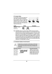
... clear the data in CMOS. Please be noted that the password, date, time and user default profile will cause permanent damage of the motherboard! Placing jumper caps over these 2 pins. When the jumper cap is placed on pins, the jumper is "Open". Jumper Clear CMOS Jumper (CLRCMOS1) (see p.12...
... clear the data in CMOS. Please be noted that the password, date, time and user default profile will cause permanent damage of the motherboard! Placing jumper caps over these 2 pins. When the jumper cap is placed on pins, the jumper is "Open". Jumper Clear CMOS Jumper (CLRCMOS1) (see p.12...
User Manual
Page 25
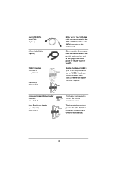
... Audio Cable (Optional) Either end of the SATA data cable can be connected to the SATA / SATAII hard disk or the SATAII connector on this motherboard. Either end of the 3.5mm audio cable can support two USB 2.0 ports. Each USB 2.0 header can be connected to connect the remote controller receiver. Front... (9-pin HD_AUDIO1) (see p.12 No. 9) 1 GND IRTX IRRX ATX+5VSB Besides four default USB 2.0 ports on the I/O panel, there are two USB 2.0 headers on this motherboard.
... Audio Cable (Optional) Either end of the SATA data cable can be connected to the SATA / SATAII hard disk or the SATAII connector on this motherboard. Either end of the 3.5mm audio cable can support two USB 2.0 ports. Each USB 2.0 header can be connected to connect the remote controller receiver. Front... (9-pin HD_AUDIO1) (see p.12 No. 9) 1 GND IRTX IRRX ATX+5VSB Besides four default USB 2.0 ports on the I/O panel, there are two USB 2.0 headers on this motherboard.
User Manual
Page 27
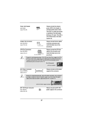
... it can work if you plan to connect the 3-Pin CPU fan to the CPU fan connector on when the system is off ). Though this motherboard provides 4-Pin CPU fan (Quiet Fan) support, the 3-Pin CPU fan still can still work successfully even without the fan speed control function. The LED... Pin 1 and Pin 13. 24 13 ATX 12V Power Connector (4-pin ATX12V1) (see p.12 No. 7) 12 13 Please connect an ATX power supply to this motherboard provides 24-pin ATX power connector, it to the ground pin.
... it can work if you plan to connect the 3-Pin CPU fan to the CPU fan connector on when the system is off ). Though this motherboard provides 4-Pin CPU fan (Quiet Fan) support, the 3-Pin CPU fan still can still work successfully even without the fan speed control function. The LED... Pin 1 and Pin 13. 24 13 ATX 12V Power Connector (4-pin ATX12V1) (see p.12 No. 7) 12 13 Please connect an ATX power supply to this motherboard provides 24-pin ATX power connector, it to the ground pin.

User Manual
Page 28
...Function? STEP 2: Connect the SATA power cable to the SATA / SATAII hard disk. 2.12 Hot Plug Function for SATA / SATAII HDDs This motherboard supports Hot Plug function for internal storage devices. STEP 4: Connect the other end of your chassis. If the SATA / SATAII HDDs are NOT ... the SATA / SATAII hard disks into the SATA / SATAII HDD. 28 2.11 Serial ATA (SATA) / Serial ATAII (SATAII) Hard Disks Installation This motherboard adopts Intel® H61 chipset that it is called "Hot Plug" for SATA host controllers developed thru a joint industry effort. You may install SATA / ...
...Function? STEP 2: Connect the SATA power cable to the SATA / SATAII hard disk. 2.12 Hot Plug Function for SATA / SATAII HDDs This motherboard supports Hot Plug function for internal storage devices. STEP 4: Connect the other end of your chassis. If the SATA / SATAII HDDs are NOT ... the SATA / SATAII hard disks into the SATA / SATAII HDD. 28 2.11 Serial ATA (SATA) / Serial ATAII (SATAII) Hard Disks Installation This motherboard adopts Intel® H61 chipset that it is called "Hot Plug" for SATA host controllers developed thru a joint industry effort. You may install SATA / ...

