
User Manual
Page 3
... Slots (PCI Express Slots 20 2.7 Jumpers Setup 21 2.8 Onboard Headers and Connectors 22 2.9 Driver Installation Guide 27 3 UEFI SETUP UTILITY 28 3.1 Introduction 28 3.1.1 UEFI Menu Bar 28 3.1.2 Navigation Keys 29 3.2 Main Screen 29 3.3 OC Tweaker Screen 30 3.4 Advanced Screen 34 3.4.1 CPU Configuration 35 3.4.2 North Bridge Configuration 37 3.4.3 South Bridge Configuration 38 3.4.4 Storage Configuration 39 3.4.5 Intel(R) Rapid Start Technology 40 3.4.6 Intel(R) Smart Connect Technology 41 3.4.7 Super IO Configuration 42 3.4.8 ACPI Configuration 43 3.4.9 USB Configuration...
... Slots (PCI Express Slots 20 2.7 Jumpers Setup 21 2.8 Onboard Headers and Connectors 22 2.9 Driver Installation Guide 27 3 UEFI SETUP UTILITY 28 3.1 Introduction 28 3.1.1 UEFI Menu Bar 28 3.1.2 Navigation Keys 29 3.2 Main Screen 29 3.3 OC Tweaker Screen 30 3.4 Advanced Screen 34 3.4.1 CPU Configuration 35 3.4.2 North Bridge Configuration 37 3.4.3 South Bridge Configuration 38 3.4.4 Storage Configuration 39 3.4.5 Intel(R) Rapid Start Technology 40 3.4.6 Intel(R) Smart Connect Technology 41 3.4.7 Super IO Configuration 42 3.4.8 ACPI Configuration 43 3.4.9 USB Configuration...
User Manual
Page 5
... ASRock H61M-DG4 Motherboard (Micro ATX Form Factor) ASRock H61M-DG4 Quick Installation Guide ASRock H61M-DG4 Support CD 2 x Serial ATA (SATA) Data Cables (Optional) 1 x I/O Panel Shield ASRock Reminds You... You may find the latest VGA cards and CPU support lists on ASRock website without notice. To get better performance in Windows® 8 / 8 64-bit / 7 / 7 64-bit / VistaTM / VistaTM 64-bit, it is recommended to set the BIOS option in Storage Configuration to the hardware installation. In this motherboard, please visit our website for specific information about the model...
... ASRock H61M-DG4 Motherboard (Micro ATX Form Factor) ASRock H61M-DG4 Quick Installation Guide ASRock H61M-DG4 Support CD 2 x Serial ATA (SATA) Data Cables (Optional) 1 x I/O Panel Shield ASRock Reminds You... You may find the latest VGA cards and CPU support lists on ASRock website without notice. To get better performance in Windows® 8 / 8 64-bit / 7 / 7 64-bit / VistaTM / VistaTM 64-bit, it is recommended to set the BIOS option in Storage Configuration to the hardware installation. In this motherboard, please visit our website for specific information about the model...

User Manual
Page 6
... supports PCIE 2.0. - 1 x PCI Express 2.0 x1 Slot * Intel® HD Graphics Built-in Visuals: Intel® Quick Sync Video 2.0, Intel® InTruTM 3D, Intel® Clear Video HD Technology, Intel® InsiderTM, Intel® HD Graphics 2500/4000 with Intel® Sandy Bridge CPU. 6 Max. shared memory 1759MB with Intel® Ivy Bridge CPU - Supports Intel® Rapid Start Technology and Smart Connect Technology - Supports Intel® HD Graphics Built-in Visuals and the VGA...
... supports PCIE 2.0. - 1 x PCI Express 2.0 x1 Slot * Intel® HD Graphics Built-in Visuals: Intel® Quick Sync Video 2.0, Intel® InTruTM 3D, Intel® Clear Video HD Technology, Intel® InsiderTM, Intel® HD Graphics 2500/4000 with Intel® Sandy Bridge CPU. 6 Max. shared memory 1759MB with Intel® Ivy Bridge CPU - Supports Intel® Rapid Start Technology and Smart Connect Technology - Supports Intel® HD Graphics Built-in Visuals and the VGA...

User Manual
Page 7
... max. HD Audio Jacks: Line in/Front Speaker/Microphone - 4 x SATA2 3.0 Gb/s Connectors, support NCQ, AHCI and Hot Plug - 1 x IR Header - 1 x Print Port Header - 1 x COM Port Header - 1 x Power LED Header - 1 x Chassis Intrusion Header - 1 x TPM Header - 1 x CPU Fan Connector (4-pin) - 1 x Chassis Fan Connector (4-pin) - 1 x 24 pin ATX Power Connector - 1 x 4 pin 12V Power Connector - 1 x Front Panel Audio Connector - 1 x SPDIF Out Connector - 2 x USB 2.0 Headers (Support 4 USB 2.0 ports) 7 Supports D-Sub with DVI-D Port - 5.1 CH HD Audio (Realtek ALC662 Audio Codec) - PCIE x1 Gigabit LAN...
... max. HD Audio Jacks: Line in/Front Speaker/Microphone - 4 x SATA2 3.0 Gb/s Connectors, support NCQ, AHCI and Hot Plug - 1 x IR Header - 1 x Print Port Header - 1 x COM Port Header - 1 x Power LED Header - 1 x Chassis Intrusion Header - 1 x TPM Header - 1 x CPU Fan Connector (4-pin) - 1 x Chassis Fan Connector (4-pin) - 1 x 24 pin ATX Power Connector - 1 x 4 pin 12V Power Connector - 1 x Front Panel Audio Connector - 1 x SPDIF Out Connector - 2 x USB 2.0 Headers (Support 4 USB 2.0 ports) 7 Supports D-Sub with DVI-D Port - 5.1 CH HD Audio (Realtek ALC662 Audio Codec) - PCIE x1 Gigabit LAN...

User Manual
Page 9
... and startup process, Instant Boot allows you to your USB flash drive, floppy disk or hard drive, then you to access ASRock Instant Flash. By calling S3 and S4 at specific timing during the POST or the key to enter into the BIOS setup menu to turn on your system. Just launch this utility, you can update your Windows® desktop in a few seconds. In Fan Control, it shows the fan speed and temperature for your system. With...
... and startup process, Instant Boot allows you to your USB flash drive, floppy disk or hard drive, then you to access ASRock Instant Flash. By calling S3 and S4 at specific timing during the POST or the key to enter into the BIOS setup menu to turn on your system. Just launch this utility, you can update your Windows® desktop in a few seconds. In Fan Control, it shows the fan speed and temperature for your system. With...

User Manual
Page 13
... x 240-pin DDR3 DIMM Slots (Dual Channel: DDR3_A1, DDR3_B1) 4 ATX Power Connector (ATXPWR1) 5 Power LED Header (PLED1) 6 System Panel Header (PANEL1) 7 Chassis Fan Connector (CHA_FAN1) 8 SATA2 Connector (SATA_1) 9 SATA2 Connector (SATA_0) 10 SATA2 Connector (SATA_3) 11 SATA2 Connector (SATA_2) 12 USB 2.0 Header (USB4_5) 13 TPM Header (TPMS1) 14 USB 2.0 Header (USB6_7) 15 Infrared Module Header (IR1) 16 COM Port Header (COM1) 17 Chassis Intrusion Header (CI1) 18 Print Port Header (LPT1) 19 Front Panel Audio Header (HD_AUDIO1) 20 SPDIF Out Connector (SPDIF_OUT1) 21 Clear CMOS Jumper (CLRCMOS1...
... x 240-pin DDR3 DIMM Slots (Dual Channel: DDR3_A1, DDR3_B1) 4 ATX Power Connector (ATXPWR1) 5 Power LED Header (PLED1) 6 System Panel Header (PANEL1) 7 Chassis Fan Connector (CHA_FAN1) 8 SATA2 Connector (SATA_1) 9 SATA2 Connector (SATA_0) 10 SATA2 Connector (SATA_3) 11 SATA2 Connector (SATA_2) 12 USB 2.0 Header (USB4_5) 13 TPM Header (TPMS1) 14 USB 2.0 Header (USB6_7) 15 Infrared Module Header (IR1) 16 COM Port Header (COM1) 17 Chassis Intrusion Header (CI1) 18 Print Port Header (LPT1) 19 Front Panel Audio Header (HD_AUDIO1) 20 SPDIF Out Connector (SPDIF_OUT1) 21 Clear CMOS Jumper (CLRCMOS1...

User Manual
Page 21
..., use a jumper cap to short pin2 and pin3 on pins, the jumper is "Open". After waiting for 5 seconds. Please be noted that the password, date, time and user default profile will be detected. However, please do the clear-CMOS action. Please adjust the BIOS option "Clear Status" to clear the data in CMOS. Jumper Setting Description Clear CMOS Jumper (CLRCMOS1) (see p.13, No. 21) Default Clear CMOS Note: CLRCMOS1 allows you clear the CMOS, the case...
..., use a jumper cap to short pin2 and pin3 on pins, the jumper is "Open". After waiting for 5 seconds. Please be noted that the password, date, time and user default profile will be detected. However, please do the clear-CMOS action. Please adjust the BIOS option "Clear Status" to clear the data in CMOS. Jumper Setting Description Clear CMOS Jumper (CLRCMOS1) (see p.13, No. 21) Default Clear CMOS Note: CLRCMOS1 allows you clear the CMOS, the case...

User Manual
Page 28
... pressing the reset button on the menu bar, and then press to get into the sub screen. You can also use the UEFI SETUP UTILITY to locate and load the Operating System Security To set up the default system device to configure your screen. 3.1.1 UEFI Menu Bar The top of the screen has a menu bar with its test routines. Because the UEFI software is constantly being updated, the following selections: Main To set up...
... pressing the reset button on the menu bar, and then press to get into the sub screen. You can also use the UEFI SETUP UTILITY to locate and load the Operating System Security To set up the default system device to configure your screen. 3.1.1 UEFI Menu Bar The top of the screen has a menu bar with its test routines. Because the UEFI software is constantly being updated, the following selections: Main To set up...

User Manual
Page 35
...; Windows® XP / VistaTM / 7 / 8 is [Auto]. Enhance Halt State (C1E) All processors support the Halt State (C1). No-Execute Memory Protection No-Execution (NX) Memory Protection Technology is [All]. CPU C3 State Support Use this to enable or disable CPU C6 (ACPI C3) report to enable in each processor package. Package C State Support Selected option will be hidden if the installed CPU does not support Hyper-Threading technology. The default value is required. Set...
...; Windows® XP / VistaTM / 7 / 8 is [Auto]. Enhance Halt State (C1E) All processors support the Halt State (C1). No-Execute Memory Protection No-Execution (NX) Memory Protection Technology is [All]. CPU C3 State Support Use this to enable or disable CPU C6 (ACPI C3) report to enable in each processor package. Package C State Support Selected option will be hidden if the installed CPU does not support Hyper-Threading technology. The default value is required. Set...

User Manual
Page 37
... Standby Use this option. The default value of this feature is [Enabled]. IGPU Multi-Moniter This allows you to set onboard VGA share memory feature. The default value is [Disabled]. The default value is [Enabled]. If you install the PCI Express card under Windows® XP / VistaTM OS, please disable this to enable or disable Deep Render Standby by Internal Graphics Device. PCIE1 Link Speed This allows you to select [Onboard] or [PCI Express] as the boot graphic adapter...
... Standby Use this option. The default value of this feature is [Enabled]. IGPU Multi-Moniter This allows you to set onboard VGA share memory feature. The default value is [Disabled]. The default value is [Enabled]. If you install the PCI Express card under Windows® XP / VistaTM OS, please disable this to enable or disable Deep Render Standby by Internal Graphics Device. PCIE1 Link Speed This allows you to select [Onboard] or [PCI Express] as the boot graphic adapter...

User Manual
Page 44
... legacy USB. [Auto] - Enables legacy support if USB devices are four configuration options: [Enabled], [Auto], [Disabled] and [UEFI Setup Only]. Enables support for the details of USB 2.0 controller. If you enable Fast Boot option. USB devices are allowed to use only under legacy OS and UEFI setup when [Disabled] is recommended to select [Disabled] to enable or disable the use under UEFI setup and Windows / Linux OS. 44 The default value is [Enabled]. Legacy USB Support Use this item to enter OS. [UEFI Setup Only] - There are connected. [Disabled] - USB devices...
... legacy USB. [Auto] - Enables legacy support if USB devices are four configuration options: [Enabled], [Auto], [Disabled] and [UEFI Setup Only]. Enables support for the details of USB 2.0 controller. If you enable Fast Boot option. USB devices are allowed to use only under legacy OS and UEFI setup when [Disabled] is recommended to select [Disabled] to enable or disable the use under UEFI setup and Windows / Linux OS. 44 The default value is [Enabled]. Legacy USB Support Use this item to enter OS. [UEFI Setup Only] - There are connected. [Disabled] - USB devices...

User Manual
Page 48
... CPU temperature, motherboard temperature, CPU fan speed, chassis fan speed, and the critical voltage. CPU Fan Setting This allows you to monitor the status of the hardware on your system, including the parameters of previous chassis intrusion status. 48 The default is value [Disabled]. Clear Status This option appears only when the case open detection feature. Configuration options: [Full On] and [Automatic Mode]. Chassis Fan Setting This allows you to set the CPU fan speed. Case Open Feature This allows you to enable...
... CPU temperature, motherboard temperature, CPU fan speed, chassis fan speed, and the critical voltage. CPU Fan Setting This allows you to monitor the status of the hardware on your system, including the parameters of previous chassis intrusion status. 48 The default is value [Disabled]. Clear Status This option appears only when the case open detection feature. Configuration options: [Full On] and [Automatic Mode]. Chassis Fan Setting This allows you to set the CPU fan speed. Case Open Feature This allows you to enable...
User Manual
Page 53
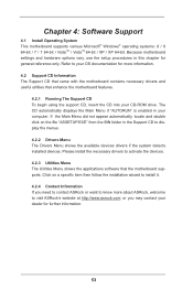
... motherboard settings and hardware options vary, use the setup procedures in the Support CD to display the menus. 4.2.2 Drivers Menu The Drivers Menu shows the available devices drivers if the system detects installed devices. If the Main Menu did not appear automatically, locate and double click on a specific item then follow the installation wizard to activate the devices. 4.2.3 Utilities Menu The Utilities Menu shows the applications software that enhance the motherboard features. 4.2.1 Running The Support CD To begin using...
... motherboard settings and hardware options vary, use the setup procedures in the Support CD to display the menus. 4.2.2 Drivers Menu The Drivers Menu shows the available devices drivers if the system detects installed devices. If the Main Menu did not appear automatically, locate and double click on a specific item then follow the installation wizard to activate the devices. 4.2.3 Utilities Menu The Utilities Menu shows the applications software that enhance the motherboard features. 4.2.1 Running The Support CD To begin using...
Quick Installation Guide
Page 2
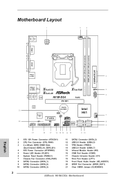
... Slots (Dual Channel: DDR3_A1, DDR3_B1) 4 ATX Power Connector (ATXPWR1) 5 Power LED Header (PLED1) 6 System Panel Header (PANEL1) 7 Chassis Fan Connector (CHA_FAN1) 8 SATA2 Connector (SATA_1) 9 SATA2 Connector (SATA_0) 10 SATA2 Connector (SATA_3) 11 SATA2 Connector (SATA_2) 12 USB 2.0 Header (USB4_5) 13 TPM Header (TPMS1) 14 USB 2.0 Header (USB6_7) 15 Infrared Module Header (IR1) 16 COM Port Header (COM1) 17 Chassis Intrusion Header (CI1) 18 Print Port Header (LPT1) 19 Front Panel Audio Header (HD_AUDIO1) 20 SPDIF Out Connector (SPDIF_OUT1) 21 Clear CMOS Jumper (CLRCMOS1) 2 ASRock H61M-DG4...
... Slots (Dual Channel: DDR3_A1, DDR3_B1) 4 ATX Power Connector (ATXPWR1) 5 Power LED Header (PLED1) 6 System Panel Header (PANEL1) 7 Chassis Fan Connector (CHA_FAN1) 8 SATA2 Connector (SATA_1) 9 SATA2 Connector (SATA_0) 10 SATA2 Connector (SATA_3) 11 SATA2 Connector (SATA_2) 12 USB 2.0 Header (USB4_5) 13 TPM Header (TPMS1) 14 USB 2.0 Header (USB6_7) 15 Infrared Module Header (IR1) 16 COM Port Header (COM1) 17 Chassis Intrusion Header (CI1) 18 Print Port Header (LPT1) 19 Front Panel Audio Header (HD_AUDIO1) 20 SPDIF Out Connector (SPDIF_OUT1) 21 Clear CMOS Jumper (CLRCMOS1) 2 ASRock H61M-DG4...
Quick Installation Guide
Page 4
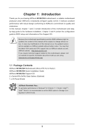
... control. You may find the latest VGA cards and CPU support lists on ASRock website without notice. For the BIOS setup, please refer to change without further notice. ASRock website http://www.asrock.com If you require technical support related to this manual will be available on ASRock website as well. www.asrock.com/support/index.asp 1.1 Package Contents ASRock H61M-DG4 Motherboard (Micro ATX Form Factor) ASRock H61M-DG4 Quick Installation Guide ASRock H61M-DG4 Support CD 2 x Serial ATA (SATA) Data Cables (Optional) 1 x I/O Panel Shield ASRock...
... control. You may find the latest VGA cards and CPU support lists on ASRock website without notice. For the BIOS setup, please refer to change without further notice. ASRock website http://www.asrock.com If you require technical support related to this manual will be available on ASRock website as well. www.asrock.com/support/index.asp 1.1 Package Contents ASRock H61M-DG4 Motherboard (Micro ATX Form Factor) ASRock H61M-DG4 Quick Installation Guide ASRock H61M-DG4 Support CD 2 x Serial ATA (SATA) Data Cables (Optional) 1 x I/O Panel Shield ASRock...

Quick Installation Guide
Page 5
...® Quick Sync Video 2.0, Intel® InTruTM 3D, Intel® Clear Video HD Technology, Intel® InsiderTM, Intel® HD Graphics 2500/4000 with Intel® Sandy Bridge CPU - Supports K-Series unlocked CPU - Supports Intel® Rapid Start Technology and Smart Connect Technology - Dual Channel DDR3 Memory Technology - 2 x DDR3 DIMM Slots - Micro ATX Form Factor - Supports Intel® Turbo Boost 2.0 Technology - English 5 ASRock H61M-DG4 Motherboard Supports Intel® HD Graphics Built-in LGA1155 package - shared memory 1759MB with Intel...
...® Quick Sync Video 2.0, Intel® InTruTM 3D, Intel® Clear Video HD Technology, Intel® InsiderTM, Intel® HD Graphics 2500/4000 with Intel® Sandy Bridge CPU - Supports K-Series unlocked CPU - Supports Intel® Rapid Start Technology and Smart Connect Technology - Dual Channel DDR3 Memory Technology - 2 x DDR3 DIMM Slots - Micro ATX Form Factor - Supports Intel® Turbo Boost 2.0 Technology - English 5 ASRock H61M-DG4 Motherboard Supports Intel® HD Graphics Built-in LGA1155 package - shared memory 1759MB with Intel...

Quick Installation Guide
Page 6
...Header - 1 x CPU Fan Connector (4-pin) - 1 x Chassis Fan Connector (4-pin) - 1 x 24 pin ATX Power Connector - 1 x 4 pin 12V Power Connector - 1 x Front Panel Audio Connector - 1 x SPDIF Out Connector - 2 x USB 2.0 Headers (Support 4 USB 2.0 ports) English 6 ASRock H61M-DG4 Motherboard resolution up to 1920x1200 @ 60Hz - resolution up to 2048x1536 @ 75Hz - Supports Full HD 1080p Blu-ray (BD) playback with max. Realtek RTL8111C - Dual VGA output: support DVI-D and D-Sub ports by independent display controllers - Supports LAN Cable Detection - Audio LAN Rear Panel I/O Storage...
...Header - 1 x CPU Fan Connector (4-pin) - 1 x Chassis Fan Connector (4-pin) - 1 x 24 pin ATX Power Connector - 1 x 4 pin 12V Power Connector - 1 x Front Panel Audio Connector - 1 x SPDIF Out Connector - 2 x USB 2.0 Headers (Support 4 USB 2.0 ports) English 6 ASRock H61M-DG4 Motherboard resolution up to 1920x1200 @ 60Hz - resolution up to 2048x1536 @ 75Hz - Supports Full HD 1080p Blu-ray (BD) playback with max. Realtek RTL8111C - Dual VGA output: support DVI-D and D-Sub ports by independent display controllers - Supports LAN Cable Detection - Audio LAN Rear Panel I/O Storage...
Quick Installation Guide
Page 8
... utilizes the memory space that the USB flash drive or hard drive must use FAT32/16/12 file system. 8 ASRock H61M-DG4 Motherboard English In XFast RAM, it shows the fan speed and temperature for your Windows® desktop in Windows® to ne-tune different system functions in a user-friendly interface, which normally enable the Sleep/Standby and Hibernation modes in a few clicks without entering operating systems first like MSDOS or Windows®. This convenient BIOS update...
... utilizes the memory space that the USB flash drive or hard drive must use FAT32/16/12 file system. 8 ASRock H61M-DG4 Motherboard English In XFast RAM, it shows the fan speed and temperature for your Windows® desktop in Windows® to ne-tune different system functions in a user-friendly interface, which normally enable the Sleep/Standby and Hibernation modes in a few clicks without entering operating systems first like MSDOS or Windows®. This convenient BIOS update...

Quick Installation Guide
Page 13
... clear the CMOS, the case open may be cleared only if the CMOS battery is "Short". English 13 ASRock H61M-DG4 Motherboard If no jumper cap is placed on pins, the jumper is placed on these 2 pins. 1.5 Jumpers Setup The illustration shows how jumpers are "Short" when jumper cap is "Open". When the jumper cap is placed on CLRCMOS1 for 15 seconds, use a jumper cap to default setup, please turn off the computer and unplug the power...
... clear the CMOS, the case open may be cleared only if the CMOS battery is "Short". English 13 ASRock H61M-DG4 Motherboard If no jumper cap is placed on pins, the jumper is placed on these 2 pins. 1.5 Jumpers Setup The illustration shows how jumpers are "Short" when jumper cap is "Open". When the jumper cap is placed on CLRCMOS1 for 15 seconds, use a jumper cap to default setup, please turn off the computer and unplug the power...
Quick Installation Guide
Page 19
...: 8 / 8 64-bit / 7 / 7 64-bit / VistaTM / VistaTM 64-bit / XP / XP 64-bit. When you to scroll through its test routines. If you wish to the User Manual (PDF file) contained in the Support CD to enter BIOS Setup utility; The BIOS Setup program is a menu-driven program, which allows you start up the computer, please press or during the Power-On-Self-Test (POST) to display the menus. 19 ASRock H61M-DG4 Motherboard English
...: 8 / 8 64-bit / 7 / 7 64-bit / VistaTM / VistaTM 64-bit / XP / XP 64-bit. When you to scroll through its test routines. If you wish to the User Manual (PDF file) contained in the Support CD to enter BIOS Setup utility; The BIOS Setup program is a menu-driven program, which allows you start up the computer, please press or during the Power-On-Self-Test (POST) to display the menus. 19 ASRock H61M-DG4 Motherboard English


