
User Manual
Page 3
... Hybrid CrossFireXTM Operation Guide 23 2.7 CrossFireXTM and Quad CrossFireXTM Operation Guide .......... 25 2.8 Jumpers Setup 29 2.9 Onboard Headers and Connectors 30 2.10 Smart Switches 35 2.11 Dr. Debug 36 2.12 Serial ATA3 (SATA3) Hard Disks Installation 40 2.13 Hot Plug and Hot Swap Functions for SATA3 HDDs 40 2.14 SATA3 HDD Hot Plug...
... Hybrid CrossFireXTM Operation Guide 23 2.7 CrossFireXTM and Quad CrossFireXTM Operation Guide .......... 25 2.8 Jumpers Setup 29 2.9 Onboard Headers and Connectors 30 2.10 Smart Switches 35 2.11 Dr. Debug 36 2.12 Serial ATA3 (SATA3) Hard Disks Installation 40 2.13 Hot Plug and Hot Swap Functions for SATA3 HDDs 40 2.14 SATA3 HDD Hot Plug...

User Manual
Page 7
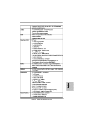
... connector - 8 pin 12V power connector - PCIE x1 Gigabit LAN 10/100/1000 Mb/s - Atheros® AR8151 - Front panel audio connector - 3 x USB 2.0 headers (support 6 USB 2.0 ports) - 1 x Dr. Debug (7-Segment Debug LED) - 1 x Clear CMOS Switch with LED - 1 x Power Switch with LED - 1 x Reset Switch with LED 7 Audio LAN Rear Panel I /O Panel - 1 x PS/2 Keyboard Port - 1 x VGA/D-Sub...
... connector - 8 pin 12V power connector - PCIE x1 Gigabit LAN 10/100/1000 Mb/s - Atheros® AR8151 - Front panel audio connector - 3 x USB 2.0 headers (support 6 USB 2.0 ports) - 1 x Dr. Debug (7-Segment Debug LED) - 1 x Clear CMOS Switch with LED - 1 x Power Switch with LED - 1 x Reset Switch with LED 7 Audio LAN Rear Panel I /O Panel - 1 x PS/2 Keyboard Port - 1 x VGA/D-Sub...
User Manual
Page 12
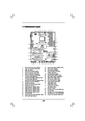
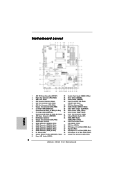
Blue) 19 Dr. Debug (LED) 39 PCI Express 2.0 x1 Slot (PCIE1; White) 20 Chassis Speaker Header (SPEAKER 1, White) 40 Chassis Fan Connector (CHA_FAN1) 21 Power LED Header (... Chipset PCI Express 2.0 PCIE2 USB 3.0 Hybrid CrossFire CMOS BATTERY 890GX Pro3 CHA_FAN3 Designed in Taipei Super I/O PCI1 PCIE3 ErP/EuP Ready AUDIO CODEC PCI2 RoHS PCI3 HD_AUDIO1 IR1 HDMI_SPDIF1 1 1 1 COM1 1 USB6_7 1 USB8_9 1 SATAIII_3_4 SATAIII_1_2 SATA3 6Gb/s AMD SB850 Chipset 1394a 32Mb BIOS CLRCMOS1 1 Dr. Debug SATA3_5 USB10_11 1 FRONT_1394 1 PWRBTN RSTBTN PANEL 1 PLED PWRBTN...
Blue) 19 Dr. Debug (LED) 39 PCI Express 2.0 x1 Slot (PCIE1; White) 20 Chassis Speaker Header (SPEAKER 1, White) 40 Chassis Fan Connector (CHA_FAN1) 21 Power LED Header (... Chipset PCI Express 2.0 PCIE2 USB 3.0 Hybrid CrossFire CMOS BATTERY 890GX Pro3 CHA_FAN3 Designed in Taipei Super I/O PCI1 PCIE3 ErP/EuP Ready AUDIO CODEC PCI2 RoHS PCI3 HD_AUDIO1 IR1 HDMI_SPDIF1 1 1 1 COM1 1 USB6_7 1 USB8_9 1 SATAIII_3_4 SATAIII_1_2 SATA3 6Gb/s AMD SB850 Chipset 1394a 32Mb BIOS CLRCMOS1 1 Dr. Debug SATA3_5 USB10_11 1 FRONT_1394 1 PWRBTN RSTBTN PANEL 1 PLED PWRBTN...

User Manual
Page 36
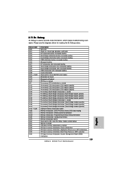
...Bridge module specific) Pre-Memory North Bridge initialization (North Bridge module specific) Pre-memory South Bridge initialization is started CPU post-memory initialization. 2.11 Dr. Debug Dr. Debug is started Pre-memory South Bridge initialization (South Bridge module specific) Pre-memory South Bridge initialization (South Bridge module specific) Pre-memory South Bridge ...North Bridge initialization after microcode loading South Bridge initialization after microcode loading OEM initialization after microcode loading Cache initialization Reserved for reading the Dr. Debug codes.
...Bridge module specific) Pre-Memory North Bridge initialization (North Bridge module specific) Pre-memory South Bridge initialization is started CPU post-memory initialization. 2.11 Dr. Debug Dr. Debug is started Pre-memory South Bridge initialization (South Bridge module specific) Pre-memory South Bridge initialization (South Bridge module specific) Pre-memory South Bridge ...North Bridge initialization after microcode loading South Bridge initialization after microcode loading OEM initialization after microcode loading Cache initialization Reserved for reading the Dr. Debug codes.
Quick Installation Guide
Page 2
... (PCIE2; Blue) 19 Dr. Debug (LED) 39 PCI Express 2.0 x1 Slot (PCIE1; Blue) 29 SB 2.0 Header (USB8_9, Blue) 9 2 x 240-pin DDR3 DIMM Slots 30 SB 2.0 Header (USB6_7, Blue) (Dual Channel B: DDR3_A2, DDR3_B2; White) 20 Chassis Speaker Header (SPEAKER 1, White) 40 Chassis Fan Connector (CHA_FAN1) 21 Power LED Header (PLED1) 2 ASRock 890GX Pro3 Motherboard Motherboard Layout...
... (PCIE2; Blue) 19 Dr. Debug (LED) 39 PCI Express 2.0 x1 Slot (PCIE1; Blue) 29 SB 2.0 Header (USB8_9, Blue) 9 2 x 240-pin DDR3 DIMM Slots 30 SB 2.0 Header (USB6_7, Blue) (Dual Channel B: DDR3_A2, DDR3_B2; White) 20 Chassis Speaker Header (SPEAKER 1, White) 40 Chassis Fan Connector (CHA_FAN1) 21 Power LED Header (PLED1) 2 ASRock 890GX Pro3 Motherboard Motherboard Layout...
Quick Installation Guide
Page 7
... 12V power connector - Atheros® AR8151 - Supports Wake-On-LAN I /O SATA3 USB 3.0 Connector Smart Switch - Front panel audio connector - 3 x USB 2.0 headers (support 6 USB 2.0 ports) - 1 x Dr. Debug (7-Segment Debug LED) - 1 x Clear CMOS Switch with LED - 1 x Power Switch with LED - 1 x Reset Switch with Content Protection (Realtek ALC892 Audio Codec) - HD Audio Jack: Rear Speaker/Central... LAN 10/100/1000 Mb/s - Supports Full HD 1080p Blu-ray (BD) / HD-DVD playback with DVI and HDMI ports - 7.1 CH HD Audio with LED 7 ASRock 890GX Pro3 Motherboard English
... 12V power connector - Atheros® AR8151 - Supports Wake-On-LAN I /O SATA3 USB 3.0 Connector Smart Switch - Front panel audio connector - 3 x USB 2.0 headers (support 6 USB 2.0 ports) - 1 x Dr. Debug (7-Segment Debug LED) - 1 x Clear CMOS Switch with LED - 1 x Power Switch with LED - 1 x Reset Switch with Content Protection (Realtek ALC892 Audio Codec) - HD Audio Jack: Rear Speaker/Central... LAN 10/100/1000 Mb/s - Supports Full HD 1080p Blu-ray (BD) / HD-DVD playback with DVI and HDMI ports - 7.1 CH HD Audio with LED 7 ASRock 890GX Pro3 Motherboard English
Quick Installation Guide
Page 33
... Bridge initialization (South Bridge module specific) OEM pre-memory initialization codes Memory initialization. Configuring memory Memory initialization (other) Reserved for reading the Dr. Debug codes. System Management Mode (SMM) initialization 33 ASRock 890GX Pro3 Motherboard English Programming memory timing information Memory initialization. Application Processor(s) (AP) initialization CPU post-memory initialization. Cache initialization CPU post-memory...
... Bridge initialization (South Bridge module specific) OEM pre-memory initialization codes Memory initialization. Configuring memory Memory initialization (other) Reserved for reading the Dr. Debug codes. System Management Mode (SMM) initialization 33 ASRock 890GX Pro3 Motherboard English Programming memory timing information Memory initialization. Application Processor(s) (AP) initialization CPU post-memory initialization. Cache initialization CPU post-memory...
