User Manual
Page 10
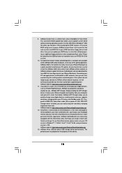
... to RAM (S3), hibernation mode (S4) or power off (S5). Please be noted that combines your most up to access ASRock Instant Flash. ASRock AIWI utility introduces a new way of charging your iPhone charged much quickly from App store to do -date supported games! Simply installing the APP Charger driver, it makes your Apple devices, such as a game joystick to your USB flash drive, floppy disk or hard drive...
... to RAM (S3), hibernation mode (S4) or power off (S5). Please be noted that combines your most up to access ASRock Instant Flash. ASRock AIWI utility introduces a new way of charging your iPhone charged much quickly from App store to do -date supported games! Simply installing the APP Charger driver, it makes your Apple devices, such as a game joystick to your USB flash drive, floppy disk or hard drive...
User Manual
Page 12
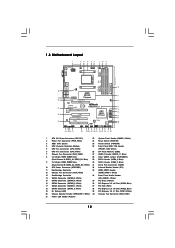
... Panel Header (PANEL1, White) 2 Power Fan Connector (PWR_FAN1) 23 Reset Switch (RSTBTN) 3 AM3+ CPU Socket 24 Power Switch (PWRBTN) 4 CPU Heatsink Retention Module 25 Front Panel IEEE 1394 Header 5 CPU Fan Connector (CPU_FAN2) (FRONT_1394, White) 6 CPU Fan Connector (CPU_FAN1) 26 SPI Flash Memory (32Mb) 7 Chassis Fan Connector (CHA_FAN2) 27 USB 2.0 Header (USB10_11, Blue) 8 2 x 240-pin DDR3 DIMM Slots 28 Clear CMOS Jumper (CLRCMOS1) (Dual Channel A: DDR3_A1, DDR3_B1; White) 20 Chassis Speaker Header (SPEAKER 1, White) 40 Chassis Fan Connector (CHA_FAN1) 21 Power LED Header...
... Panel Header (PANEL1, White) 2 Power Fan Connector (PWR_FAN1) 23 Reset Switch (RSTBTN) 3 AM3+ CPU Socket 24 Power Switch (PWRBTN) 4 CPU Heatsink Retention Module 25 Front Panel IEEE 1394 Header 5 CPU Fan Connector (CPU_FAN2) (FRONT_1394, White) 6 CPU Fan Connector (CPU_FAN1) 26 SPI Flash Memory (32Mb) 7 Chassis Fan Connector (CHA_FAN2) 27 USB 2.0 Header (USB10_11, Blue) 8 2 x 240-pin DDR3 DIMM Slots 28 Clear CMOS Jumper (CLRCMOS1) (Dual Channel A: DDR3_A1, DDR3_B1; White) 20 Chassis Speaker Header (SPEAKER 1, White) 40 Chassis Fan Connector (CHA_FAN1) 21 Power LED Header...
User Manual
Page 20
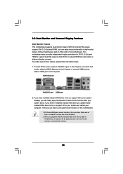
... I/O panel, connect D-Sub monitor cable to use dual monitor function on this motherboard. Then you can start to VGA/D-Sub port on the I /O panel. When one of them is enabled, the other one will be disabled. 2. 2.5 Dual Monitor and Surround Display Features Dual Monitor Feature This motherboard supports dual monitor feature. VGA/D-Sub port VGA/DVI-D port HDMI port 2. DVI-D and HDMI ports cannot function at the same time. When you playback HDCP-protected video from our support CD to this motherboard. 1. With the internal VGA...
... I/O panel, connect D-Sub monitor cable to use dual monitor function on this motherboard. Then you can start to VGA/D-Sub port on the I /O panel. When one of them is enabled, the other one will be disabled. 2. 2.5 Dual Monitor and Surround Display Features Dual Monitor Feature This motherboard supports dual monitor feature. VGA/D-Sub port VGA/DVI-D port HDMI port 2. DVI-D and HDMI ports cannot function at the same time. When you playback HDCP-protected video from our support CD to this motherboard. 1. With the internal VGA...
User Manual
Page 21
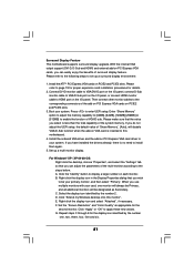
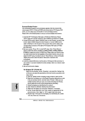
... "OK" to enable the function of surround display feature. Surround Display Feature This motherboard supports surround display upgrade. Install the ATITM PCI Express VGA cards on PCI Express VGA card driver to this monitor". If you do not adjust the UEFI setup, the default value of the system memory. For Windows® XP / XP 64-bit OS: Right click the desktop, choose "Properties", and select the "Settings" tab so that you have installed the drivers already, there is...
... "OK" to enable the function of surround display feature. Surround Display Feature This motherboard supports surround display upgrade. Install the ATITM PCI Express VGA cards on PCI Express VGA card driver to this monitor". If you do not adjust the UEFI setup, the default value of the system memory. For Windows® XP / XP 64-bit OS: Right click the desktop, choose "Properties", and select the "Settings" tab so that you have installed the drivers already, there is...

User Manual
Page 23
...? Connect the monitor cable to enter UEFI setup. Enter "Advanced" screen, and enter "North Bridge Configuration". Step 4. Step 6. Press to the correspondent connector on the PCI Express graphics card on PCIE2 slot. Then set the option "Surround View" to PCIE2 slot (blue). Please remove the ATITM driver if you will find "ATI Catalyst Control Center" on an AMD 890GX integrated chipset, all operating in your system for blisteringlyfast frame rates. Step 5. Then you have any VGA driver installed...
...? Connect the monitor cable to enter UEFI setup. Enter "Advanced" screen, and enter "North Bridge Configuration". Step 4. Step 6. Press to the correspondent connector on the PCI Express graphics card on PCIE2 slot. Then set the option "Surround View" to PCIE2 slot (blue). Please remove the ATITM driver if you will find "ATI Catalyst Control Center" on an AMD 890GX integrated chipset, all operating in your system for blisteringlyfast frame rates. Step 5. Then you have any VGA driver installed...
User Manual
Page 27
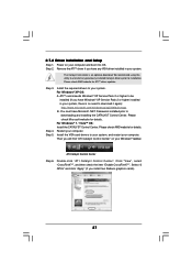
... any VGA driver installed in your computer. Step 3. Install the required drivers to be installed (If you have Windows® XP Service Pack 2 or higher installed in your Windows® taskbar. Please check Microsoft website for ATITM driver updates. Restart your system. Double-click "ATI Catalyst Control Center". The Catalyst Uninstaller is no need to downloading and installing the CATALYST Control Center. 2.7.2 Driver Installation and Setup Step 1. Please check AMD...
... any VGA driver installed in your computer. Step 3. Install the required drivers to be installed (If you have Windows® XP Service Pack 2 or higher installed in your Windows® taskbar. Please check Microsoft website for ATITM driver updates. Restart your system. Double-click "ATI Catalyst Control Center". The Catalyst Uninstaller is no need to downloading and installing the CATALYST Control Center. 2.7.2 Driver Installation and Setup Step 1. Please check AMD...

User Manual
Page 36
... Not used to provide code information, which makes troubleshooting even easier. Serial Presence Detect (SPD) data reading Memory initialization. Programming memory timing information Memory initialization. System Management Mode (SMM) initialization 36 Memory presence detection Memory initialization. Cache initialization CPU post-memory initialization. Configuring memory Memory initialization (other) Reserved for ASL (see the diagrams below ) Memory Installed CPU post-memory initialization is started CPU post-memory initialization. Reset type detection (soft/hard) AP...
... Not used to provide code information, which makes troubleshooting even easier. Serial Presence Detect (SPD) data reading Memory initialization. Programming memory timing information Memory initialization. System Management Mode (SMM) initialization 36 Memory presence detection Memory initialization. Cache initialization CPU post-memory initialization. Configuring memory Memory initialization (other) Reserved for ASL (see the diagrams below ) Memory Installed CPU post-memory initialization is started CPU post-memory initialization. Reset type detection (soft/hard) AP...
User Manual
Page 41
... our website: www.asrock.com 2. SATA data cable (Red) B. The SATA3 HDD, which cannot support Hot Plug function, will cause the HDD damage and data loss. Make sure to use the SATA power cable & data cable, which are from your dealer or HDD user manual. Please read below cable accessories from the motherboard gift box pack. SATA power cable SATA 7-pin connector The SATA 15-pin power connector (Black) connect to SATA3 HDD 1x4-pin conventional power connector (White) connect to power supply Caution 1. Points...
... our website: www.asrock.com 2. SATA data cable (Red) B. The SATA3 HDD, which cannot support Hot Plug function, will cause the HDD damage and data loss. Make sure to use the SATA power cable & data cable, which are from your dealer or HDD user manual. Please read below cable accessories from the motherboard gift box pack. SATA power cable SATA 7-pin connector The SATA 15-pin power connector (Black) connect to SATA3 HDD 1x4-pin conventional power connector (White) connect to power supply Caution 1. Points...
User Manual
Page 43
... key. B. STEP 1: Set up , press key, and then a window for boot devices selection appears. Insert the ASRock Support CD into your optical drive to install Windows® XP / XP 64-bit on the screen, "Generate Serial ATA driver diskette [YN]?", press . D. STEP 2: Make a SATA3 Driver Diskette. (Please use USB floppy or floppy disk.) A. ROM as the boot device. Set the "SATA Mode" option to install those required drivers. Then you will see the message on a RAID disk composed of 2 or more SATA3 HDDs...
... key. B. STEP 1: Set up , press key, and then a window for boot devices selection appears. Insert the ASRock Support CD into your optical drive to install Windows® XP / XP 64-bit on the screen, "Generate Serial ATA driver diskette [YN]?", press . D. STEP 2: Make a SATA3 Driver Diskette. (Please use USB floppy or floppy disk.) A. ROM as the boot device. Set the "SATA Mode" option to install those required drivers. Then you will see the message on a RAID disk composed of 2 or more SATA3 HDDs...
User Manual
Page 57
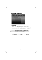
If you set this item to RAID mode, it is [Enabled]. 57 The default value is suggested to install SATA ODD driver on SATA3_5 or eSATA port. SATA IDE Combined Mode This item is [IDE Mode]. 3.4.4 Storage Configuration SATA Controller Use this item to enable or disable SATA IDE combined mode. Use this item to adjust SATA Mode. SATA Mode Use this option is for SATA3_5 and eSATA ports. The default value of this item to enable or disable the "SATA Controller" feature. Configuration options: [AHCI Mode], [RAID Mode] and [IDE Mode].
If you set this item to RAID mode, it is [Enabled]. 57 The default value is suggested to install SATA ODD driver on SATA3_5 or eSATA port. SATA IDE Combined Mode This item is [IDE Mode]. 3.4.4 Storage Configuration SATA Controller Use this item to enable or disable SATA IDE combined mode. Use this item to adjust SATA Mode. SATA Mode Use this option is for SATA3_5 and eSATA ports. The default value of this item to enable or disable the "SATA Controller" feature. Configuration options: [AHCI Mode], [RAID Mode] and [IDE Mode].

User Manual
Page 60
.... Legacy USB Support Use this option to enable or disable legacy support for USB devices. Please refer to below descriptions for legacy USB. [Auto] - Enables support for the details of USB 3.0 controller. USB devices are four confi guration options: [Enabled], [Auto], [Disabled] and [UEFI Setup Only]. There are not allowed to use under UEFI setup and Windows / Linux OS. USB 3.0 Controller Use this item to enable or disable the use of USB 2.0 controller. The default value is recommended to select [Disabled] to enter OS. [UEFI Setup Only] - 3.4.7 USB Configuration...
.... Legacy USB Support Use this option to enable or disable legacy support for USB devices. Please refer to below descriptions for legacy USB. [Auto] - Enables support for the details of USB 3.0 controller. USB devices are four confi guration options: [Enabled], [Auto], [Disabled] and [UEFI Setup Only]. There are not allowed to use under UEFI setup and Windows / Linux OS. USB 3.0 Controller Use this item to enable or disable the use of USB 2.0 controller. The default value is recommended to select [Disabled] to enter OS. [UEFI Setup Only] - 3.4.7 USB Configuration...
User Manual
Page 65
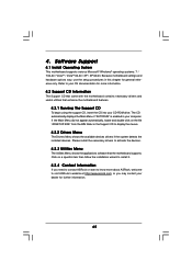
... begin using the support CD, insert the CD into your computer. Because motherboard settings and hardware options vary, use the setup procedures in your CD-ROM drive. 4. or you need to contact ASRock or want to know more information. 4.2 Support CD Information The Support CD that came with the motherboard contains necessary drivers and useful utilities that the motherboard supports. The CD automatically displays the Main Menu if "AUTORUN" is enabled in...
... begin using the support CD, insert the CD into your computer. Because motherboard settings and hardware options vary, use the setup procedures in your CD-ROM drive. 4. or you need to contact ASRock or want to know more information. 4.2 Support CD Information The Support CD that came with the motherboard contains necessary drivers and useful utilities that the motherboard supports. The CD automatically displays the Main Menu if "AUTORUN" is enabled in...
Quick Installation Guide
Page 2
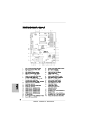
Motherboard Layout English 1 ATX 12V Power Connector (ATX12V1) 22 System Panel Header (PANEL1, White) 2 Power Fan Connector (PWR_FAN1) 23 Reset Switch (RSTBTN) 3 AM3+ CPU Socket 24 Power Switch (PWRBTN) 4 CPU Heatsink Retention Module 25 Front Panel IEEE 1394 Header 5 CPU Fan Connector (CPU_FAN2) (FRONT_1394, White) 6 CPU Fan Connector (CPU_FAN1) 26 SPI Flash Memory (32Mb) 7 Chassis Fan Connector (CHA_FAN2) 27 USB 2.0 Header (USB10_11, Blue) 8 2 x 240-pin DDR3 DIMM Slots 28 Clear CMOS Jumper (CLRCMOS1) (Dual Channel A: DDR3_A1, DDR3_B1; Blue) 17 SATA3 Connector (SATAIII_1, ...
Motherboard Layout English 1 ATX 12V Power Connector (ATX12V1) 22 System Panel Header (PANEL1, White) 2 Power Fan Connector (PWR_FAN1) 23 Reset Switch (RSTBTN) 3 AM3+ CPU Socket 24 Power Switch (PWRBTN) 4 CPU Heatsink Retention Module 25 Front Panel IEEE 1394 Header 5 CPU Fan Connector (CPU_FAN2) (FRONT_1394, White) 6 CPU Fan Connector (CPU_FAN1) 26 SPI Flash Memory (32Mb) 7 Chassis Fan Connector (CHA_FAN2) 27 USB 2.0 Header (USB10_11, Blue) 8 2 x 240-pin DDR3 DIMM Slots 28 Clear CMOS Jumper (CLRCMOS1) (Dual Channel A: DDR3_A1, DDR3_B1; Blue) 17 SATA3 Connector (SATAIII_1, ...
Quick Installation Guide
Page 17
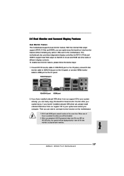
... ASRock 890GX Pro3 Motherboard English This motherboard also provides independent display controllers for DVI-D, D-Sub and HDMI to this motherboard. 1. When you can start to VGA/D-Sub port on the I /O panel. Connect DVI-D monitor cable to VGA/DVI-D port on the I/O panel, connect D-Sub monitor cable to use dual monitor function on this motherboard. To enable dual monitor feature, please follow the below steps: 1. If you haven't installed onboard VGA driver yet, please install onboard VGA driver from our support CD to your system and restart your system boots...
... ASRock 890GX Pro3 Motherboard English This motherboard also provides independent display controllers for DVI-D, D-Sub and HDMI to this motherboard. 1. When you can start to VGA/D-Sub port on the I /O panel. Connect DVI-D monitor cable to VGA/DVI-D port on the I/O panel, connect D-Sub monitor cable to use dual monitor function on this motherboard. To enable dual monitor feature, please follow the below steps: 1. If you haven't installed onboard VGA driver yet, please install onboard VGA driver from our support CD to your system and restart your system boots...
Quick Installation Guide
Page 18
... multi-monitor according to display a large number on PCI Express VGA cards, you do not adjust the UEFI setup, the default value of VGA/D-sub. Right-click the display icon and select "Attached", if necessary. Click "Apply" or "OK" to enter UEFI setup. Then connect other monitor cables to enable the function of "Share Memory", [Auto], will be your card, one , two, three, four, five and six. 18 ASRock 890GX Pro3 Motherboard English Enter "Share Memory" option to...
... multi-monitor according to display a large number on PCI Express VGA cards, you do not adjust the UEFI setup, the default value of VGA/D-sub. Right-click the display icon and select "Attached", if necessary. Click "Apply" or "OK" to enter UEFI setup. Then connect other monitor cables to enable the function of "Share Memory", [Auto], will be your card, one , two, three, four, five and six. 18 ASRock 890GX Pro3 Motherboard English Enter "Share Memory" option to...
Quick Installation Guide
Page 24
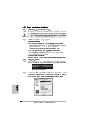
... Radeon graphics cards). Power on your computer. Step 4. For Windows® XP OS: A. ATI Catalyst Control Center Step 6. English 24 ASRock 890GX Pro3 Motherboard You must have any previously installed Catalyst drivers prior to download it again): http://www.microsoft.com/windowsxp/sp2/default.mspx B. Install the required drivers to your system, and restart your Windows® taskbar. Step 3. Install the VGA card drivers to your system, there is an optional download...
... Radeon graphics cards). Power on your computer. Step 4. For Windows® XP OS: A. ATI Catalyst Control Center Step 6. English 24 ASRock 890GX Pro3 Motherboard You must have any previously installed Catalyst drivers prior to download it again): http://www.microsoft.com/windowsxp/sp2/default.mspx B. Install the required drivers to your system, and restart your Windows® taskbar. Step 3. Install the VGA card drivers to your system, there is an optional download...
Quick Installation Guide
Page 33
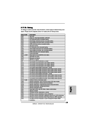
...Installed CPU post-memory initialization is started Pre-memory South Bridge initialization (South Bridge module specific) Pre-memory South Bridge initialization (South Bridge module specific) Pre-memory South Bridge initialization (South Bridge module specific) OEM pre-memory initialization codes Memory initialization. Application Processor(s) (AP) initialization CPU post-memory initialization. System Management Mode (SMM) initialization 33 ASRock 890GX Pro3 Motherboard English Cache initialization CPU post-memory initialization. 2.11 Dr. Debug Dr. Debug is used Power on. Reset type...
...Installed CPU post-memory initialization is started Pre-memory South Bridge initialization (South Bridge module specific) Pre-memory South Bridge initialization (South Bridge module specific) Pre-memory South Bridge initialization (South Bridge module specific) OEM pre-memory initialization codes Memory initialization. Application Processor(s) (AP) initialization CPU post-memory initialization. System Management Mode (SMM) initialization 33 ASRock 890GX Pro3 Motherboard English Cache initialization CPU post-memory initialization. 2.11 Dr. Debug Dr. Debug is used Power on. Reset type...
RAID Installation Guide
Page 4
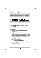
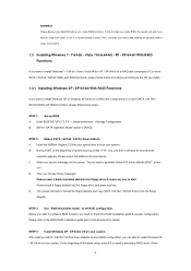
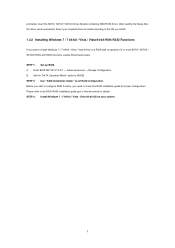
... / XP 64-bit on a RAID disk composed of 2 or more SATA / SATAII / SATA3 HDDs with RAID functions, please follow below steps. A. Please select CD-ROM as the boot device. D. At the beginning of system boot-up BIOS. Please backup your system. Set the "SATA Operation Mode" option to the BIOS RAID installation guide part in this RAID installation guide for boot devices selection appears. B. C. E. STEP 3: Use "RAID Installation Guide" to set RAID configuration, you will operate under a clean environment. 1.3 Installing Windows 7 / 7 64-bit / Vista / Vista...
... / XP 64-bit on a RAID disk composed of 2 or more SATA / SATAII / SATA3 HDDs with RAID functions, please follow below steps. A. Please select CD-ROM as the boot device. D. At the beginning of system boot-up BIOS. Please backup your system. Set the "SATA Operation Mode" option to the BIOS RAID installation guide part in this RAID installation guide for boot devices selection appears. B. C. E. STEP 3: Use "RAID Installation Guide" to set RAID configuration, you will operate under a clean environment. 1.3 Installing Windows 7 / 7 64-bit / Vista / Vista...
RAID Installation Guide
Page 5
... RAID Functions If you need to check this document for proper configuration. prompted, insert the SATA / SATAII / SATA3 driver diskette containing AMD RAID driver. After reading the floppy disk, the driver will be presented. B. Set the "SATA Operation Mode" option to set RAID configuration. STEP 2: Use "RAID Installation Guide" to [RAID]. STEP 3: Install Windows 7 / 7 64-bit / Vista / Vista 64-bit OS on a RAID disk composed of 2 or more SATA / SATAII / SATA3 HDDs with RAID functions, please follow below steps. STEP 1: Set up BIOS...
... RAID Functions If you need to check this document for proper configuration. prompted, insert the SATA / SATAII / SATA3 driver diskette containing AMD RAID driver. After reading the floppy disk, the driver will be presented. B. Set the "SATA Operation Mode" option to set RAID configuration. STEP 2: Use "RAID Installation Guide" to [RAID]. STEP 3: Install Windows 7 / 7 64-bit / Vista / Vista 64-bit OS on a RAID disk composed of 2 or more SATA / SATAII / SATA3 HDDs with RAID functions, please follow below steps. STEP 1: Set up BIOS...
RAID Installation Guide
Page 10
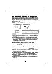
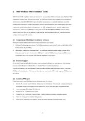
... the default browser. Follow the prompts in order to access RAIDXpert over the network. 2.3 Installing RAIDXpert Follow these steps to your CD-ROM drive. 3. Its browser-based GUI provides email notification of the following browsers: Internet Explorer 6.0, Mozilla Suite 1.7, Mozilla Firefox 1.0, or Netscape Navigator 7.1. Boot the PC or server, launch Windows, and log in the RAID configuration (server, controller, logical drives, physical drives...
... the default browser. Follow the prompts in order to access RAIDXpert over the network. 2.3 Installing RAIDXpert Follow these steps to your CD-ROM drive. 3. Its browser-based GUI provides email notification of the following browsers: Internet Explorer 6.0, Mozilla Suite 1.7, Mozilla Firefox 1.0, or Netscape Navigator 7.1. Boot the PC or server, launch Windows, and log in the RAID configuration (server, controller, logical drives, physical drives...


