User Manual
Page 5
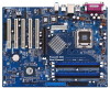
...-bystep guide to BIOS setup and information of this manual will be available on ASRock website as well. ASRock website http://www.asrock.com 1.1 Package Contents ASRock 775V88/775V88+ Motherboard (ATX Form Factor: 12.0-in x 9.2-in, 30.5 cm x 23.4 cm) ASRock 775V88/775V88+ Quick Installation Guide ASRock 775V88/775V88+ Support CD (including LGA 775 CPU Installation Live Demo) One 80-conductor Ultra...
...-bystep guide to BIOS setup and information of this manual will be available on ASRock website as well. ASRock website http://www.asrock.com 1.1 Package Contents ASRock 775V88/775V88+ Motherboard (ATX Form Factor: 12.0-in x 9.2-in, 30.5 cm x 23.4 cm) ASRock 775V88/775V88+ Quick Installation Guide ASRock 775V88/775V88+ Support CD (including LGA 775 CPU Installation Live Demo) One 80-conductor Ultra...
Quick Installation Guide
Page 1
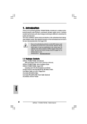
..., or translated in any language, in any form or by any defect or error in the guide or product. All rights reserved. 1 ASRock 775V88/775V88+ Motherboard English ASRock assumes no event shall ASRock, its directors, officers, employees, or agents be liable for any indirect, special, incidental, or consequential damages (including damages for loss of profits...
..., or translated in any language, in any form or by any defect or error in the guide or product. All rights reserved. 1 ASRock 775V88/775V88+ Motherboard English ASRock assumes no event shall ASRock, its directors, officers, employees, or agents be liable for any indirect, special, incidental, or consequential damages (including damages for loss of profits...
Quick Installation Guide
Page 2
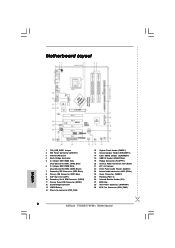
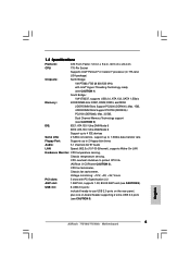
... Game Connector (GAME1) 25 PCI Slots (PCI 1-5) 26 Infrared Module Header (IR1) 27 BIOS chip 28 ATX Power Connector (ATXPWR1) 29 CPU Fan Connector (CPU_FAN1) 2 ASRock 775V88/775V88+ Motherboard Motherboard Layout English 1 PS2_USB_PWR1 Jumper 2 ATX Power Connector (ATX12V1) 3 775-Pin CPU Socket 4 North Bridge Controller 5 2 x 184-pin DDR DIMM Slots (Dual Channel A: DDR1...
... Game Connector (GAME1) 25 PCI Slots (PCI 1-5) 26 Infrared Module Header (IR1) 27 BIOS chip 28 ATX Power Connector (ATXPWR1) 29 CPU Fan Connector (CPU_FAN1) 2 ASRock 775V88/775V88+ Motherboard Motherboard Layout English 1 PS2_USB_PWR1 Jumper 2 ATX Power Connector (ATX12V1) 3 775-Pin CPU Socket 4 North Bridge Controller 5 2 x 184-pin DDR DIMM Slots (Dual Channel A: DDR1...
Quick Installation Guide
Page 3
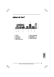
ASRock I/O PlusTM 1 Parallel Port 2 RJ-45 Port 3 Line In (Light Blue) 4 Line Out (Lime) 5 Microphone (Pink) 6 USB 2.0 Ports (USB4, USB5) 7 USB 2.0 Ports (USB0, USB1) 8 USB 2.0 Ports (USB2, USB3) 9 Serial Port: COM1 10 PS/2 Keyboard Port (Purple) 11 PS/2 Mouse Port (Green) English 3 ASRock 775V88/775V88+ Motherboard
ASRock I/O PlusTM 1 Parallel Port 2 RJ-45 Port 3 Line In (Light Blue) 4 Line Out (Lime) 5 Microphone (Pink) 6 USB 2.0 Ports (USB4, USB5) 7 USB 2.0 Ports (USB0, USB1) 8 USB 2.0 Ports (USB2, USB3) 9 Serial Port: COM1 10 PS/2 Keyboard Port (Purple) 11 PS/2 Mouse Port (Green) English 3 ASRock 775V88/775V88+ Motherboard
Quick Installation Guide
Page 4
... (SATA) HDD Power Cable (Optional) One ASRock I/O PlusTM Shield 4 ASRock 775V88/775V88+ Motherboard English In case any modifications of the motherboard can be available on ASRock website as well. ASRock website http://www.asrock.com 1.1 Package Contents ASRock 775V88/775V88+ Motherboard (ATX Form Factor: 12.0-in x 9.2-in, 30.5 cm x 23.4 cm) ASRock 775V88/775V88+ Quick Installation Guide ASRock 775V88/775V88+ Support CD (including LGA 775 CPU...
... (SATA) HDD Power Cable (Optional) One ASRock I/O PlusTM Shield 4 ASRock 775V88/775V88+ Motherboard English In case any modifications of the motherboard can be available on ASRock website as well. ASRock website http://www.asrock.com 1.1 Package Contents ASRock 775V88/775V88+ Motherboard (ATX Form Factor: 12.0-in x 9.2-in, 30.5 cm x 23.4 cm) ASRock 775V88/775V88+ Quick Installation Guide ASRock 775V88/775V88+ Support CD (including LGA 775 CPU...
Quick Installation Guide
Page 5
...: Speed: 802.3u (10/100 Ethernet), supports Wake-On-LAN Hardware Monitor: CPU temperature sensing, Chassis temperature sensing, CPU overheat shutdown to protect CPU life (ASRock U-COP)(see CAUTION 3), CPU fan tachometer, Chassis fan tachometer, Voltage monitoring: +12V, +5V, +3V, Vcore PCI slots: 5 slots with PCI Specification 2.2 AGP slot: 1 AGP slot... 4) USB 2.0: 8 USB 2.0 ports: include 6 ready-to-use USB 2.0 ports on the rear panel, plus one on-board header supporting 2 extra USB 2.0 ports (see CAUTION 5) English 5 ASRock 775V88/775V88+ Motherboard
...: Speed: 802.3u (10/100 Ethernet), supports Wake-On-LAN Hardware Monitor: CPU temperature sensing, Chassis temperature sensing, CPU overheat shutdown to protect CPU life (ASRock U-COP)(see CAUTION 3), CPU fan tachometer, Chassis fan tachometer, Voltage monitoring: +12V, +5V, +3V, Vcore PCI slots: 5 slots with PCI Specification 2.2 AGP slot: 1 AGP slot... 4) USB 2.0: 8 USB 2.0 ports: include 6 ready-to-use USB 2.0 ports on the rear panel, plus one on-board header supporting 2 extra USB 2.0 ports (see CAUTION 5) English 5 ASRock 775V88/775V88+ Motherboard
Quick Installation Guide
Page 6
...instability of "Hyper Threading Technology", please check page 27 in the support CD. 2. Power Management for proper installation. 3. English 6 ASRock 775V88/775V88+ Motherboard Before you implement Dual Channel Memory Technology, make sure to spray thermal grease between the CPU and the heatsink when you resume ...may not work properly under Microsoft® Windows® XP SP1/2000 SP4. This motherboard supports Dual Channel Memory Technology. ASRock I/O PlusTM: 1 PS/2 mouse port, 1 PS/2 keyboard port, 1 serial port: COM1, 1 parallel port: ECP/EPP support, 6 ready-to...
...instability of "Hyper Threading Technology", please check page 27 in the support CD. 2. Power Management for proper installation. 3. English 6 ASRock 775V88/775V88+ Motherboard Before you implement Dual Channel Memory Technology, make sure to spray thermal grease between the CPU and the heatsink when you resume ...may not work properly under Microsoft® Windows® XP SP1/2000 SP4. This motherboard supports Dual Channel Memory Technology. ASRock I/O PlusTM: 1 PS/2 mouse port, 1 PS/2 keyboard port, 1 serial port: COM1, 1 parallel port: ECP/EPP support, 6 ready-to...
Quick Installation Guide
Page 7
...strap or touch a safety grounded object before touching any motherboard settings. 1. Failure to do not touch the ICs. 4. Installation 775V88/775V88+ is detached from the wall socket before you install motherboard components or change any component. 2. 2. Before you install the ... the motherboard components due to static electricity, NEVER place your chassis to the motherboard, peripherals, and/or components. 7 ASRock 775V88/775V88+ Motherboard English Pre-installation Precautions Take note of your motherboard directly on a grounded antistatic pad or in the bag that...
...strap or touch a safety grounded object before touching any motherboard settings. 1. Failure to do not touch the ICs. 4. Installation 775V88/775V88+ is detached from the wall socket before you install motherboard components or change any component. 2. 2. Before you install the ... the motherboard components due to static electricity, NEVER place your chassis to the motherboard, peripherals, and/or components. 7 ASRock 775V88/775V88+ Motherboard English Pre-installation Precautions Take note of your motherboard directly on a grounded antistatic pad or in the bag that...
Quick Installation Guide
Page 8
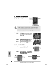
... depressing down and out on the socket. Pin1 orientation key notch orientation key notch Pin1 alignment key alignment key 775-Pin Socket 775-LAND CPU 8 ASRock 775V88/775V88+ Motherboard black line black line English Step 1-3. Orient the CPU with black lines. Locate Pin1 and the two orientation key notches. Otherwise, the CPU will...
... depressing down and out on the socket. Pin1 orientation key notch orientation key notch Pin1 alignment key alignment key 775-Pin Socket 775-LAND CPU 8 ASRock 775V88/775V88+ Motherboard black line black line English Step 1-3. Orient the CPU with black lines. Locate Pin1 and the two orientation key notches. Otherwise, the CPU will...
Quick Installation Guide
Page 9
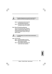
.... Step 2-3. Step 4-3. For proper inserting, please ensure to match the two orientation key notches of the CPU with the two alignment keys of load lever. 9 ASRock 775V88/775V88+ Motherboard English Secure load lever with load plate tab under retention tab of the socket.
.... Step 2-3. Step 4-3. For proper inserting, please ensure to match the two orientation key notches of the CPU with the two alignment keys of load lever. 9 ASRock 775V88/775V88+ Motherboard English Secure load lever with load plate tab under retention tab of the socket.
Quick Installation Guide
Page 10
... the CPU and the heatsink to improve heat dissipation. Step 6. Please adopt the type of heatsink and cooling fan compliant with each other components. 10 ASRock 775V88/775V88+ Motherboard English Then connect the CPU fan to the CPU_FAN connector (CPU_FAN1, see page 2, No. 29). Repeat with the motherboard throughholes. 2.2 Installation of CPU Fan...
... the CPU and the heatsink to improve heat dissipation. Step 6. Please adopt the type of heatsink and cooling fan compliant with each other components. 10 ASRock 775V88/775V88+ Motherboard English Then connect the CPU fan to the CPU_FAN connector (CPU_FAN1, see page 2, No. 29). Repeat with the motherboard throughholes. 2.2 Installation of CPU Fan...
Quick Installation Guide
Page 11
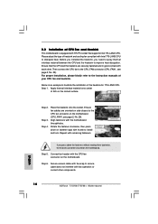
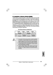
... reliability, it is unable to install them either in the set of Memory Modules (DIMM) 775V88/775V88+ motherboard provides four 184-pin DDR (Double Data Rate) DIMM slots, and supports Dual Channel Memory Technology. English 11 ASRock 775V88/775V88+ Motherboard Blue slots; If only one memory module or three memory modules are installed in all...
... reliability, it is unable to install them either in the set of Memory Modules (DIMM) 775V88/775V88+ motherboard provides four 184-pin DDR (Double Data Rate) DIMM slots, and supports Dual Channel Memory Technology. English 11 ASRock 775V88/775V88+ Motherboard Blue slots; If only one memory module or three memory modules are installed in all...
Quick Installation Guide
Page 12
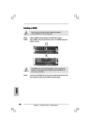
English 12 ASRock 775V88/775V88+ Motherboard The DIMM only fits in place and the DIMM is properly seated. It will cause permanent damage to disconnect power supply before adding or ...
English 12 ASRock 775V88/775V88+ Motherboard The DIMM only fits in place and the DIMM is properly seated. It will cause permanent damage to disconnect power supply before adding or ...
Quick Installation Guide
Page 13
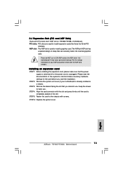
... STEP 4: Align the card connector with the slot and press firmly until the card is unplugged. STEP 6: Replace the system cover. 13 ASRock 775V88/775V88+ Motherboard English It may cause permanent damage! STEP 2: Remove the system unit cover (if your AGP card, please check with screws. Please...motherboard is used to install expansion cards that you start the installation. PCI slots: PCI slots are 5 PCI slots and 1 AGP slot on 775V88/775V88+ motherboard. Please do NOT use . 2.4 Expansion Slots (PCI and AGP Slots) There are used to install a graphics card. Keep the screws...
... STEP 4: Align the card connector with the slot and press firmly until the card is unplugged. STEP 6: Replace the system cover. 13 ASRock 775V88/775V88+ Motherboard English It may cause permanent damage! STEP 2: Remove the system unit cover (if your AGP card, please check with screws. Please...motherboard is used to install expansion cards that you start the installation. PCI slots: PCI slots are 5 PCI slots and 1 AGP slot on 775V88/775V88+ motherboard. Please do NOT use . 2.4 Expansion Slots (PCI and AGP Slots) There are used to install a graphics card. Keep the screws...
Quick Installation Guide
Page 14
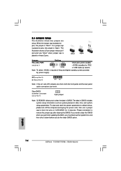
... the clear-CMOS action. If you need to clear the CMOS when you just finish updating the BIOS, you must boot up events. English 14 ASRock 775V88/775V88+ Motherboard 2.5 Jumpers Setup The illustration shows how jumpers are short, both the front panel and the rear panel audio connectors can work. If no jumper...
... the clear-CMOS action. If you need to clear the CMOS when you just finish updating the BIOS, you must boot up events. English 14 ASRock 775V88/775V88+ Motherboard 2.5 Jumpers Setup The illustration shows how jumpers are short, both the front panel and the rear panel audio connectors can work. If no jumper...
Quick Installation Guide
Page 15
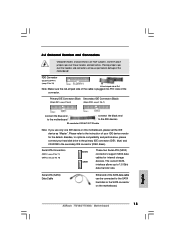
...). FDD Connector (33-pin FLOPPY1) (see p.2 No. 10) SATA2 SATA1 These two Serial ATA (SATA) connectors support SATA data cables for the details. English 15 ASRock 775V88/775V88+ Motherboard
...). FDD Connector (33-pin FLOPPY1) (see p.2 No. 10) SATA2 SATA1 These two Serial ATA (SATA) connectors support SATA data cables for the details. English 15 ASRock 775V88/775V88+ Motherboard
Quick Installation Guide
Page 16
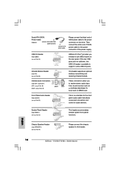
..., or MPEG card. System Panel Header (9-pin PANEL1) (see p.2, No. 18) ASRock I/O PlusTM provides you to -use USB 2.0 ports on the drive. USB 2.0 Header (9-pin USB67) (see p.2, No. 15) This header accommodates several system front panel functions. English 16 ASRock 775V88/775V88+ Motherboard Then connect the white end of SATA power cable to support...
..., or MPEG card. System Panel Header (9-pin PANEL1) (see p.2, No. 18) ASRock I/O PlusTM provides you to -use USB 2.0 ports on the drive. USB 2.0 Header (9-pin USB67) (see p.2, No. 15) This header accommodates several system front panel functions. English 16 ASRock 775V88/775V88+ Motherboard Then connect the white end of SATA power cable to support...

Quick Installation Guide
Page 17
.... 2) Please connect the chassis fan cable to this connector and match the black wire to this connector. Please note that it is installed. English 17 ASRock 775V88/775V88+ Motherboard Please connect an ATX power supply to the ground pin. You may connect either a 3-pin or a 4-pin CPU fan cable to this connector so...
.... 2) Please connect the chassis fan cable to this connector and match the black wire to this connector. Please note that it is installed. English 17 ASRock 775V88/775V88+ Motherboard Please connect an ATX power supply to the ground pin. You may connect either a 3-pin or a 4-pin CPU fan cable to this connector so...
Quick Installation Guide
Page 18
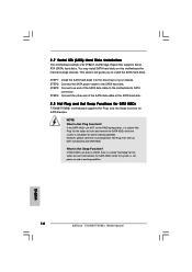
... Devices. What is Hot Plug Function? This section will guide you to the SATA hard disk. 2.8 Hot Plug and Hot Swap Functions for SATA HDDs 775V88/775V88+ motherboard supports Hot Plug and Hot Swap functions for internal storage devices. However, please note that supports Serial ATA (SATA) hard disks. 2.7 Serial ATA (SATA... into the drive bays of your chassis. NOTE What is Hot Swap Function? You may install SATA hard disks on and in working condition. 18 ASRock 775V88/775V88+ Motherboard English
... Devices. What is Hot Plug Function? This section will guide you to the SATA hard disk. 2.8 Hot Plug and Hot Swap Functions for SATA HDDs 775V88/775V88+ motherboard supports Hot Plug and Hot Swap functions for internal storage devices. However, please note that supports Serial ATA (SATA) hard disks. 2.7 Serial ATA (SATA... into the drive bays of your chassis. NOTE What is Hot Swap Function? You may install SATA hard disks on and in working condition. 18 ASRock 775V88/775V88+ Motherboard English
Quick Installation Guide
Page 19
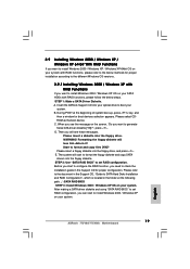
D. Then you can start to install Windows 2000 / Windows XP on your system. 19 ASRock 775V88/775V88+ Motherboard English Please insert a floppy diskette into the floppy drive. E. The system will lose ALL data in it! STEP 1: Make a SATA Driver Diskette. During ...proper configuration. C. Before you start to format the floppy diskette and copy SATA drivers into your optical drive to boot your system. WARNING! Insert the ASRock Support CD into the floppy diskette. Please select CDROM as the boot device. When you see these messages, Please insert a diskette into the floppy ...
D. Then you can start to install Windows 2000 / Windows XP on your system. 19 ASRock 775V88/775V88+ Motherboard English Please insert a floppy diskette into the floppy drive. E. The system will lose ALL data in it! STEP 1: Make a SATA Driver Diskette. During ...proper configuration. C. Before you start to format the floppy diskette and copy SATA drivers into your optical drive to boot your system. WARNING! Insert the ASRock Support CD into the floppy diskette. Please select CDROM as the boot device. When you see these messages, Please insert a diskette into the floppy ...


