RAID Installation Guide
Page 2
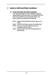
... to install the SATA hard disks. STEP 1: Install the SATA hard disks into the drive bays of the SATA data cable to the motherboard's SATA connector. STEP 4: Connect the other end of the SATA data cable to SATA Hard Disks Installation 1.1 Serial ATA (SATA) Hard Disks... Installation This motherboard adopts VIA VT8237 southbridge chipset that supports Serial ATA (SATA) hard disks. 1. Guide to the SATA hard disk. 2 You may install SATA hard disks on this motherboard for internal storage devices. STEP 3: Connect one end of your chassis...
... to install the SATA hard disks. STEP 1: Install the SATA hard disks into the drive bays of the SATA data cable to the motherboard's SATA connector. STEP 4: Connect the other end of the SATA data cable to SATA Hard Disks Installation 1.1 Serial ATA (SATA) Hard Disks... Installation This motherboard adopts VIA VT8237 southbridge chipset that supports Serial ATA (SATA) hard disks. 1. Guide to the SATA hard disk. 2 You may install SATA hard disks on this motherboard for internal storage devices. STEP 3: Connect one end of your chassis...
RAID Installation Guide
Page 4
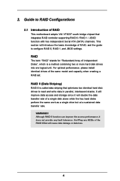
... integrates RAID controller supporting RAID 0 / RAID 1 / JBOD function with two independent Serial ATA (SATA) channels. For optimal performance, please install identical drives of RAID This motherboard adopts VIA VT8237 south bridge chipset that optimizes two identical hard disk drives to RAID Configurations 2.1 Introduction of the same model and capacity when creating...
... integrates RAID controller supporting RAID 0 / RAID 1 / JBOD function with two independent Serial ATA (SATA) channels. For optimal performance, please install identical drives of RAID This motherboard adopts VIA VT8237 south bridge chipset that optimizes two identical hard disk drives to RAID Configurations 2.1 Introduction of the same model and capacity when creating...
User Manual
Page 3
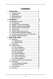
Introduction 5 1.1 Package Contents 5 1.2 Specifications 6 1.3 Motherboard Layout 8 1.4 ASRock I/O Plus 9 TM 2. Contents 1. Installation 10 Pre-installation Precautions 10 2.1 CPU Installation 11 2.2 Installation of CPU Fan and Heatsink 13 2.3 Installation of Memory Modules (DIMM 14 2.4 ...
Introduction 5 1.1 Package Contents 5 1.2 Specifications 6 1.3 Motherboard Layout 8 1.4 ASRock I/O Plus 9 TM 2. Contents 1. Installation 10 Pre-installation Precautions 10 2.1 CPU Installation 11 2.2 Installation of CPU Fan and Heatsink 13 2.3 Installation of Memory Modules (DIMM 14 2.4 ...
User Manual
Page 5
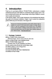
... software might be updated, the content of this manual will be subject to quality and endurance. ASRock website http://www.asrock.com 1.1 Package Contents ASRock 775V88/775V88+ Motherboard (ATX Form Factor: 12.0-in x 9.2-in, 30.5 cm x 23.4 cm) ASRock 775V88/775V88+ Quick Installation Guide ASRock 775V88/775V88+ Support CD (including LGA 775 CPU Installation Live Demo) One 80-conductor Ultra ATA 66...
... software might be updated, the content of this manual will be subject to quality and endurance. ASRock website http://www.asrock.com 1.1 Package Contents ASRock 775V88/775V88+ Motherboard (ATX Form Factor: 12.0-in x 9.2-in, 30.5 cm x 23.4 cm) ASRock 775V88/775V88+ Quick Installation Guide ASRock 775V88/775V88+ Support CD (including LGA 775 CPU Installation Live Demo) One 80-conductor Ultra ATA 66...
User Manual
Page 7
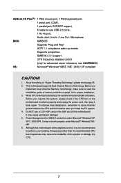
... implement Dual Channel Memory Technology, make sure to read the installation guide of memory modules on the AGP slot of this motherboard offers stepless control, it back again. While CPU overheat is not recommended to perform over-clocking. It may cause the ... fine under Microsoft® Windows® 98 / ME. 6. Frequencies other than the recommended CPU bus frequencies may cause permanent damage! 5. This motherboard supports Dual Channel Memory Technology. ASRock I/O PlusTM: 1 PS/2 mouse port, 1 PS/2 keyboard port, 1 serial port: COM1, 1 parallel port: ECP/EPP support, 6 ready...
... implement Dual Channel Memory Technology, make sure to read the installation guide of memory modules on the AGP slot of this motherboard offers stepless control, it back again. While CPU overheat is not recommended to perform over-clocking. It may cause the ... fine under Microsoft® Windows® 98 / ME. 6. Frequencies other than the recommended CPU bus frequencies may cause permanent damage! 5. This motherboard supports Dual Channel Memory Technology. ASRock I/O PlusTM: 1 PS/2 mouse port, 1 PS/2 keyboard port, 1 serial port: COM1, 1 parallel port: ECP/EPP support, 6 ready...
User Manual
Page 8
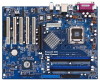
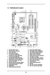
1.3 Motherboard Layout 12 PS2 Mouse 1 PS2_USB_PWR1 ATX12V1 Ps2 Keyboard PARALLEL PORT COM1 34 23.4cm (9.2 in) 56 DDR3 (64/72 bit, 184-pin module) DDR4 (64/... GAME1 PCI 3 USB2.0 AGP 8X VIA VT8237 AUX1 CD1 23 Audio CODEC AUDIO1 22 21 1 JR1 JL1 PCI 4 FSB800 DDR400 CMOS Battery PCI 5 CLRCMOS1 FLOPPY1 775V88+ 1 USB67 1 SPEAKER1 PLED PWRBTN 1 HDLED RESET PANEL 1 CHA_FAN1 20 19 18 17 16 15 30.5cm (12.0in) 7 8 9 10 11 12 13 14 1 PS2_USB_PWR1 Jumper...
1.3 Motherboard Layout 12 PS2 Mouse 1 PS2_USB_PWR1 ATX12V1 Ps2 Keyboard PARALLEL PORT COM1 34 23.4cm (9.2 in) 56 DDR3 (64/72 bit, 184-pin module) DDR4 (64/... GAME1 PCI 3 USB2.0 AGP 8X VIA VT8237 AUX1 CD1 23 Audio CODEC AUDIO1 22 21 1 JR1 JL1 PCI 4 FSB800 DDR400 CMOS Battery PCI 5 CLRCMOS1 FLOPPY1 775V88+ 1 USB67 1 SPEAKER1 PLED PWRBTN 1 HDLED RESET PANEL 1 CHA_FAN1 20 19 18 17 16 15 30.5cm (12.0in) 7 8 9 10 11 12 13 14 1 PS2_USB_PWR1 Jumper...

User Manual
Page 10
... component, place it . 2. Pre-installation Precautions Take note of your motherboard directly on a grounded antistatic pad or in , 30.5 cm x 23.4 cm) motherboard. Also remember to ensure that comes with the component. Installation 775V88/775V88+ is detached from the wall socket before touching any motherboard settings. 1. Hold components by the edges and do so may...
... component, place it . 2. Pre-installation Precautions Take note of your motherboard directly on a grounded antistatic pad or in , 30.5 cm x 23.4 cm) motherboard. Also remember to ensure that comes with the component. Installation 775V88/775V88+ is detached from the wall socket before touching any motherboard settings. 1. Hold components by the edges and do so may...
User Manual
Page 13
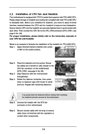
...be secured on the socket surface. Ensure that the CPU and the heatsink are oriented on side closest to the CPU fan connector on the motherboard. Then connect the CPU fan to the CPU_FAN connector (CPU_FAN1, see page 8, No. 29). Below is equipped with each other components. ...13 Step 3. Step 6. 2.2 Installation of CPU Fan and Heatsink This motherboard is an example to illustrate the installation of the heatsink for 775-LAND CPU. Step 2. Repeat with the motherboard throughholes. Before you installed the heatsink, you press down on fastener caps with the...
...be secured on the socket surface. Ensure that the CPU and the heatsink are oriented on side closest to the CPU fan connector on the motherboard. Then connect the CPU fan to the CPU_FAN connector (CPU_FAN1, see page 8, No. 29). Below is equipped with each other components. ...13 Step 3. Step 6. 2.2 Installation of CPU Fan and Heatsink This motherboard is an example to illustrate the installation of the heatsink for 775-LAND CPU. Step 2. Repeat with the motherboard throughholes. Before you installed the heatsink, you press down on fastener caps with the...
User Manual
Page 14
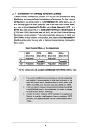
...always need to install identical (the same brand, speed, size and chip-type) DDR DIMM pair in the DDR DIMM slots on this motherboard, it is unable to the Dual Channel Memory Configuration Table below. Populated - (2) - Populated (3)* Populated Populated Populated Populated * For ...the configuration (3), please install identical DDR DIMMs in the slots of the same color. If a pair of Memory Modules (DIMM) 775V88/775V88+ motherboard provides four 184-pin DDR (Double Data Rate) DIMM slots, and supports Dual Channel Memory Technology. 2.3 Installation of memory modules is ...
...always need to install identical (the same brand, speed, size and chip-type) DDR DIMM pair in the DDR DIMM slots on this motherboard, it is unable to the Dual Channel Memory Configuration Table below. Populated - (2) - Populated (3)* Populated Populated Populated Populated * For ...the configuration (3), please install identical DDR DIMMs in the slots of the same color. If a pair of Memory Modules (DIMM) 775V88/775V88+ motherboard provides four 184-pin DDR (Double Data Rate) DIMM slots, and supports Dual Channel Memory Technology. 2.3 Installation of memory modules is ...

User Manual
Page 15
.... 15 Firmly insert the DIMM into the slot at both ends fully snap back in one correct orientation. Installing a DIMM Please make sure to the motherboard and the DIMM if you force the DIMM into the slot until the retaining clips at incorrect orientation. Step 1. Align a DIMM on the slot such...
.... 15 Firmly insert the DIMM into the slot at both ends fully snap back in one correct orientation. Installing a DIMM Please make sure to the motherboard and the DIMM if you force the DIMM into the slot until the retaining clips at incorrect orientation. Step 1. Align a DIMM on the slot such...
User Manual
Page 16
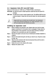
... intend to use. Align the card connector with screws. Fasten the card to install expansion cards that you start the installation. The ASRock AGP slot has a special design of the expansion card and make sure that can securely fasten the inserted graphics card. It may...the documentation of clasp that the power supply is switched off or the power cord is completely seated on 775V88/775V88+ motherboard. Step 3. Replace the system cover. 16 For the voltage information of this motherboard! Step 4. PCI slots: PCI slots are 5 PCI slots and 1 AGP slot on the slot. ...
... intend to use. Align the card connector with screws. Fasten the card to install expansion cards that you start the installation. The ASRock AGP slot has a special design of the expansion card and make sure that can securely fasten the inserted graphics card. It may...the documentation of clasp that the power supply is switched off or the power cord is completely seated on 775V88/775V88+ motherboard. Step 3. Replace the system cover. 16 For the voltage information of this motherboard! Step 4. PCI slots: PCI slots are 5 PCI slots and 1 AGP slot on the slot. ...
User Manual
Page 18
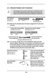
... connectors will cause permanent damage of your hard disk drive to the primary IDE connector (IDE1, blue) and CD-ROM to the instruction of the motherboard! FDD Connector (33-pin FLOPPY1) (see p.8, No. 10) SATA2 SATA1 These two Serial ATA (SATA) connectors support SATA data cables for the details....and performance, please connect your IDE device vendor for internal storage devices. Besides, to the SATA hard disk or the SATA connector on this motherboard, please set the IDE device as "Master". The current SATA interface allows up to the IDE devices 80-conductor ATA 66/100/133 cable...
... connectors will cause permanent damage of your hard disk drive to the primary IDE connector (IDE1, blue) and CD-ROM to the instruction of the motherboard! FDD Connector (33-pin FLOPPY1) (see p.8, No. 10) SATA2 SATA1 These two Serial ATA (SATA) connectors support SATA data cables for the details....and performance, please connect your IDE device vendor for internal storage devices. Besides, to the SATA hard disk or the SATA connector on this motherboard, please set the IDE device as "Master". The current SATA interface allows up to the IDE devices 80-conductor ATA 66/100/133 cable...
User Manual
Page 21
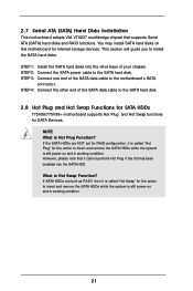
.... 21 STEP 3: Connect one end of the SATA data cable to the SATA hard disk. 2.8 Hot Plug and Hot Swap Functions for SATA HDDs 775V88/775V88+ motherboard supports Hot Plug and Hot Swap functions for SATA Devices. STEP 4: Connect the other end of your chassis. If the SATA HDDs are built as...disks into the SATA HDD. STEP 2: Connect the SATA power cable to install the SATA hard disks. 2.7 Serial ATA (SATA) Hard Disks Installation This motherboard adopts VIA VT8237 southbridge chipset that it is called "Hot Plug" for the action to insert and remove the SATA HDDs while the system is...
.... 21 STEP 3: Connect one end of the SATA data cable to the SATA hard disk. 2.8 Hot Plug and Hot Swap Functions for SATA HDDs 775V88/775V88+ motherboard supports Hot Plug and Hot Swap functions for SATA Devices. STEP 4: Connect the other end of your chassis. If the SATA HDDs are built as...disks into the SATA HDD. STEP 2: Connect the SATA power cable to install the SATA hard disks. 2.7 Serial ATA (SATA) Hard Disks Installation This motherboard adopts VIA VT8237 southbridge chipset that it is called "Hot Plug" for the action to insert and remove the SATA HDDs while the system is...

User Manual
Page 23
... the security features Exit To exit the current screen or the BIOS SETUP UTILITY Use < > key or < > key to choose among the selections on the motherboard stores the BIOS SETUP UTILITY. Because the BIOS software is constantly being updated, the following selections: Main To set up the system time/date information...
... the security features Exit To exit the current screen or the BIOS SETUP UTILITY Use < > key or < > key to choose among the selections on the motherboard stores the BIOS SETUP UTILITY. Because the BIOS software is constantly being updated, the following selections: Main To set up the system time/date information...
User Manual
Page 25
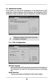
... to set the configurations for better system stability. 25 CPU Host Frequency While entering setup, BIOS auto detects the present CPU host frequency of this motherboard. Main BIOS SETUP UTILITY Advanced H/W Monitor Boot Security Exit Advanced Settings WARNING : Setting wrong values in the following items: CPU Configuration, Chipset Configuration, ACPI Configuration...
... to set the configurations for better system stability. 25 CPU Host Frequency While entering setup, BIOS auto detects the present CPU host frequency of this motherboard. Main BIOS SETUP UTILITY Advanced H/W Monitor Boot Security Exit Advanced Settings WARNING : Setting wrong values in the following items: CPU Configuration, Chipset Configuration, ACPI Configuration...
User Manual
Page 26
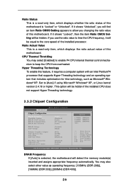
...[200MHz (DDR 400)]. 26 Hyper Threading Technology To enable this feature, it will be equal to the core speed of this motherboard is selected, the motherboard will detect the memory module(s) inserted and assigns appropriate frequency automatically. Set to keep the CPU from overheated. This option will ...value of the installed processor. Ratio Actual Value This is a read -only item, which displays the ratio actual value of this motherboard. CPU Thermal Throttling You may also select other value as Microsoft® Windows® XP. DRAM Frequency If [Auto] is "Locked" ...
...[200MHz (DDR 400)]. 26 Hyper Threading Technology To enable this feature, it will be equal to the core speed of this motherboard is selected, the motherboard will detect the memory module(s) inserted and assigns appropriate frequency automatically. Set to keep the CPU from overheated. This option will ...value of the installed processor. Ratio Actual Value This is a read -only item, which displays the ratio actual value of this motherboard. CPU Thermal Throttling You may also select other value as Microsoft® Windows® XP. DRAM Frequency If [Auto] is "Locked" ...
User Manual
Page 27
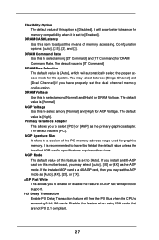
... Rate Use this to adjust the means of memory accessing. It is a 4X-AGP card, then you to enable or disable the feature of this motherboard, you may select [Auto], [8X] or [4X] as the AGP mode. Flexibility Option The default value of this feature when using ISA cards that are...
... Rate Use this to adjust the means of memory accessing. It is a 4X-AGP card, then you to enable or disable the feature of this motherboard, you may select [Auto], [8X] or [4X] as the AGP mode. Flexibility Option The default value of this feature when using ISA cards that are...

User Manual
Page 34
... Drives Configure Settings during System Boot. 3.4 Hardware Health Event Monitoring Screen In this section, it allows you to monitor the status of the CPU temperature, motherboard temperature, CPU fan speed, chassis fan speed, and the critical voltage.
... Drives Configure Settings during System Boot. 3.4 Hardware Health Event Monitoring Screen In this section, it allows you to monitor the status of the CPU temperature, motherboard temperature, CPU fan speed, chassis fan speed, and the critical voltage.
User Manual
Page 38
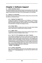
...ME / 2000 / XP. We hope you may find this live demo program before you start the installation of CPU and motherboard damages caused by improper handling, ASRock sincerely presents you a clear installation guide through the following path: ..\ MPEGAV \ LGA775INST.DAT 4.2.5 Contact Information If you ...on a specific item then follow the installation wizard to visit ASRock's website at http://www.asrock.com; The CD automatically displays the Main Menu if "AUTORUN" is a new CPU socket interface that enhance the motherboard features. 4.2.1 Running The Support CD To begin using the ...
...ME / 2000 / XP. We hope you may find this live demo program before you start the installation of CPU and motherboard damages caused by improper handling, ASRock sincerely presents you a clear installation guide through the following path: ..\ MPEGAV \ LGA775INST.DAT 4.2.5 Contact Information If you ...on a specific item then follow the installation wizard to visit ASRock's website at http://www.asrock.com; The CD automatically displays the Main Menu if "AUTORUN" is a new CPU socket interface that enhance the motherboard features. 4.2.1 Running The Support CD To begin using the ...
Quick Installation Guide
Page 1
... or explanation and to the owners' benefit, without written consent of the FCC Rules. This device complies with Part 15 of ASRock Inc. All rights reserved. 1 ASRock 775V88/775V88+ Motherboard English ASRock assumes no event shall ASRock, its directors, officers, employees, or agents be constructed as a commitment by the purchaser for backup purpose, without intent to the...
... or explanation and to the owners' benefit, without written consent of the FCC Rules. This device complies with Part 15 of ASRock Inc. All rights reserved. 1 ASRock 775V88/775V88+ Motherboard English ASRock assumes no event shall ASRock, its directors, officers, employees, or agents be constructed as a commitment by the purchaser for backup purpose, without intent to the...


