Spec Sheet_2436Vwa
Page 1
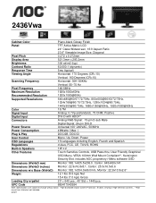
...-black Glossy Finish TFT Active Matrix LCD 24" Class Widescreen, 16:9 Aspect Ratio 23.6" Viewable Image Size, Diagonal 0.272 x 0.272mm 521.3mm x 293.2mm 300 cd/m2 (typ) Contrast Ratio Response Time Viewing Angle 60,000:1 (dynamic) 5ms (typical) Horizontal: 170 Degrees (CR>10) Vertical: 160 Degrees (CR>10) Scanning Frequency Horizontal: 30K~80KHz Vertical: 55~75 Hz Pixel Frequency Maximum Resolution Recommended Resolution Supported Resolutions Color Signal Input Digital Input Connectors Power Source Power Consumption Plug & Play User Control OSD Languages...
...-black Glossy Finish TFT Active Matrix LCD 24" Class Widescreen, 16:9 Aspect Ratio 23.6" Viewable Image Size, Diagonal 0.272 x 0.272mm 521.3mm x 293.2mm 300 cd/m2 (typ) Contrast Ratio Response Time Viewing Angle 60,000:1 (dynamic) 5ms (typical) Horizontal: 170 Degrees (CR>10) Vertical: 160 Degrees (CR>10) Scanning Frequency Horizontal: 30K~80KHz Vertical: 55~75 Hz Pixel Frequency Maximum Resolution Recommended Resolution Supported Resolutions Color Signal Input Digital Input Connectors Power Source Power Consumption Plug & Play User Control OSD Languages...
User's Manual_2436Vwa
Page 2
... Setup Stand & Base...11 Adjusting Viewing Angle...12 Connecting the Monitor...13 Wall Mounting ...14 Adjusting ...15 Setting Optimal Resolution ...15 Windows Vista ...15 Windows XP ...17 Windows ME/2000...18 Hotkeys ...19 OSD Setting...20 Eco mode ...21 Color Boost...23 Luminance ...25 Image Setup ...27 Color Temperature ...29 Picture Boost ...31 Extra Setting ...33 Exit...35 LED Indicator ...36 Driver ...37 Monitor Driver ...37 Windows 2000 ...37 Windows ME...37 Windows XP ...38 Windows Vista ...41 Windows 7 ...43 i-Menu ...47 Troubleshoot ...48 Specification...50 General Specification...
... Setup Stand & Base...11 Adjusting Viewing Angle...12 Connecting the Monitor...13 Wall Mounting ...14 Adjusting ...15 Setting Optimal Resolution ...15 Windows Vista ...15 Windows XP ...17 Windows ME/2000...18 Hotkeys ...19 OSD Setting...20 Eco mode ...21 Color Boost...23 Luminance ...25 Image Setup ...27 Color Temperature ...29 Picture Boost ...31 Extra Setting ...33 Exit...35 LED Indicator ...36 Driver ...37 Monitor Driver ...37 Windows 2000 ...37 Windows ME...37 Windows XP ...38 Windows Vista ...41 Windows 7 ...43 i-Menu ...47 Troubleshoot ...48 Specification...50 General Specification...
User's Manual_2436Vwa
Page 5
... overload power strips and extension cords. This plug will not be used for monitors with a third (grounding) pin. To ensure satisfactory operation, use the monitor only with UL listed computers which have an electrician install the correct outlet, or use only with the attached power adapter (Output 12Vdc) which have UL,CSA listed license (Only for long periods of power supplied to power surges...
... overload power strips and extension cords. This plug will not be used for monitors with a third (grounding) pin. To ensure satisfactory operation, use the monitor only with UL listed computers which have an electrician install the correct outlet, or use only with the attached power adapter (Output 12Vdc) which have UL,CSA listed license (Only for long periods of power supplied to power surges...

User's Manual_2436Vwa
Page 13
... computer's D-Sub port. 3 Connect the audio cable to the computer‟s DVI port. 5 Turn on the back of Monitor and Computer: 1. Connect one end of the 15-pin D-Sub cable to the back of the monitor and connect the other end to audio in port on your monitor displays an image, installation is complete. Requires a video card with DVI port) - If it does not display an image, please refer Troubleshooting. 13 Connecting the Monitor Cable Connections On Back of...
... computer's D-Sub port. 3 Connect the audio cable to the computer‟s DVI port. 5 Turn on the back of Monitor and Computer: 1. Connect one end of the 15-pin D-Sub cable to the back of the monitor and connect the other end to audio in port on your monitor displays an image, installation is complete. Requires a video card with DVI port) - If it does not display an image, please refer Troubleshooting. 13 Connecting the Monitor Cable Connections On Back of...
User's Manual_2436Vwa
Page 14
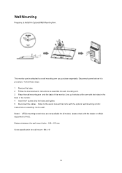
... wall mounting arm onto the back of the monitor. Noted : VESA mounting screw holes are not available for wall-mount : M4 x 10 14 Follow these steps: 1 Remove the base. 2 Follow the manufacturer's instructions to the wall. This monitor can be attached to Install An Optional Wall Mounting Arm. Distance between the wall-mount holes : 100 x 100 mm Screw specification for all models, please check with the holes in the back of AOC. Disconnect power...
... wall mounting arm onto the back of the monitor. Noted : VESA mounting screw holes are not available for wall-mount : M4 x 10 14 Follow these steps: 1 Remove the base. 2 Follow the manufacturer's instructions to the wall. This monitor can be attached to Install An Optional Wall Mounting Arm. Distance between the wall-mount holes : 100 x 100 mm Screw specification for all models, please check with the holes in the back of AOC. Disconnect power...
User's Manual_2436Vwa
Page 18
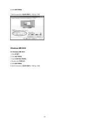
Windows ME/2000 For Windows ME/2000: 1 Click START. 2 Click SETTINGS. 3 Click CONTROL PANEL. 4 Double click DISPLAY. 5 Click SETTINGS. 6 Set the resolution SLIDE-BAR to 1920 by 1080. 18 6 Click SETTINGS. 7 Set the resolution SLIDE-BAR to 1920 by 1080.
Windows ME/2000 For Windows ME/2000: 1 Click START. 2 Click SETTINGS. 3 Click CONTROL PANEL. 4 Double click DISPLAY. 5 Click SETTINGS. 6 Set the resolution SLIDE-BAR to 1920 by 1080. 18 6 Click SETTINGS. 7 Set the resolution SLIDE-BAR to 1920 by 1080.
User's Manual_2436Vwa
Page 19
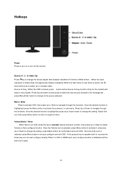
..., press Menu button to activate it is DVI or HDMI input, auto configure function is disabled and the auto icon is disabled. Select Exit icon then press Menu button to return to select up or increase value. Menu / Enter Press to activate OSD, then press Up or Down to change the setting, press Menu button for the models with dual or more inputs) .Press Source button continuously to select the input source showed...
..., press Menu button to activate it is DVI or HDMI input, auto configure function is disabled and the auto icon is disabled. Select Exit icon then press Menu button to return to select up or increase value. Menu / Enter Press to activate OSD, then press Up or Down to change the setting, press Menu button for the models with dual or more inputs) .Press Source button continuously to select the input source showed...
User's Manual_2436Vwa
Page 20
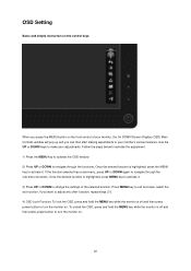
... start making adjustments to navigate through the functions. Follow the steps below to activate the adjustment. 1) Press the MENU key to activate the OSD window. 2) Press UP or DOWN to turn the monitor on the control keys. OSD Setting Basic and simple instruction on . 20 Once the desired function is off and then press power button to activate it . 3) Press UP or DOWN to change the settings...
... start making adjustments to navigate through the functions. Follow the steps below to activate the adjustment. 1) Press the MENU key to activate the OSD window. 2) Press UP or DOWN to turn the monitor on the control keys. OSD Setting Basic and simple instruction on . 20 Once the desired function is off and then press power button to activate it . 3) Press UP or DOWN to change the settings...
User's Manual_2436Vwa
Page 28
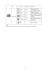
Exit Exit to reduce Vertical-Line noise. Adjust Picture Phase to reduce Horizontal-Line noise Adjust the vertical position of the picture. Adjust the horizontal position of the picture. Item Icon Function Adjust Range Description Image Setup Clock 00-100 Phase 00-100 H.Position 00-100 V.Position 00-100 Adjust picture Clock to main menu Notes : When the input source is digital signal like DVI or HDMI, Image Setup can not be adjusted. 28
Exit Exit to reduce Vertical-Line noise. Adjust Picture Phase to reduce Horizontal-Line noise Adjust the vertical position of the picture. Adjust the horizontal position of the picture. Item Icon Function Adjust Range Description Image Setup Clock 00-100 Phase 00-100 H.Position 00-100 V.Position 00-100 Adjust picture Clock to main menu Notes : When the input source is digital signal like DVI or HDMI, Image Setup can not be adjusted. 28
User's Manual_2436Vwa
Page 32
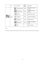
Item Picture Boost Icon Function Adjust Range Horizontal Position 00-100 Vertical Position 00-100 Contrast 00-100 Description Adjust Frame horizontal Position Adjust Frame vertical Position Adjust Frame Contrast Brightness 00-100 Adjust Frame Brightness Frame Size Bright Frame Exit 14-100 Adjust Frame Size on or off Disable or Enable Bright Frame Exit to main menu Notes : One of DCR, Color Boost, and Picture Boost functions is active, the other two function is turned off accordingly. 32
Item Picture Boost Icon Function Adjust Range Horizontal Position 00-100 Vertical Position 00-100 Contrast 00-100 Description Adjust Frame horizontal Position Adjust Frame vertical Position Adjust Frame Contrast Brightness 00-100 Adjust Frame Brightness Frame Size Bright Frame Exit 14-100 Adjust Frame Size on or off Disable or Enable Bright Frame Exit to main menu Notes : One of DCR, Color Boost, and Picture Boost functions is active, the other two function is turned off accordingly. 32
User's Manual_2436Vwa
Page 34
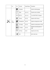
Item Icon Function Adjust Range Description Language Select the OSD language Reset yes or no Reset the menu to main menu 34 Position 00-100 V. Position 00-100 Off Timer 00-24 Adjust the OSD Timeout Adjust the transparence of OSD Adjust the vertical position of OSD Adjust the horizontal position of OSD Adjust the DC off time Exit Exit to default DDC-CI yes or no Turn ON/OFF DDC-CI Support Extra Setting Timeout 05-120 Transparence 00-100 H.
Item Icon Function Adjust Range Description Language Select the OSD language Reset yes or no Reset the menu to main menu 34 Position 00-100 V. Position 00-100 Off Timer 00-24 Adjust the OSD Timeout Adjust the transparence of OSD Adjust the vertical position of OSD Adjust the horizontal position of OSD Adjust the DC off time Exit Exit to default DDC-CI yes or no Turn ON/OFF DDC-CI Support Extra Setting Timeout 05-120 Transparence 00-100 H.
User's Manual_2436Vwa
Page 37
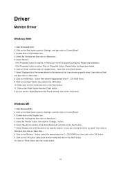
... monitor model and click on the 'Next' button. 7. Start Windows® Me 2. Click on the 'Finish' button then the 'Close' button. Click on the 'Browse...' Driver Monitor Driver Windows 2000 1. Select the 'Monitor' button, then click on the 'OK' button. 9. Please stop installation. - button, select the appropriate drive F: ( CD-ROM Drive) then click on 'Change...' Click on the 'Start' button, point to 'Settings', and then click on 'Control Panel'. 3. Click on the 'Start' button...
... monitor model and click on the 'Next' button. 7. Start Windows® Me 2. Click on the 'Finish' button then the 'Close' button. Click on the 'Browse...' Driver Monitor Driver Windows 2000 1. Select the 'Monitor' button, then click on the 'OK' button. 9. Please stop installation. - button, select the appropriate drive F: ( CD-ROM Drive) then click on 'Change...' Click on the 'Start' button, point to 'Settings', and then click on 'Control Panel'. 3. Click on the 'Start' button...
User's Manual_2436Vwa
Page 39
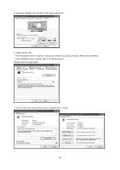
Please follow the steps below. 7. If the 'Properties' button is properly configured. Click on the 'Driver' tab and then click on the 'Advanced' button. 6. Select 'Monitor' tab - Please stop installation. - Select the 'Settings' tab then click on 'Update Driver...' If the 'Properties' button is inactive, it means your monitor is active, click on 'Properties' button. button. 39 5.
Please follow the steps below. 7. If the 'Properties' button is properly configured. Click on the 'Driver' tab and then click on the 'Advanced' button. 6. Select 'Monitor' tab - Please stop installation. - Select the 'Settings' tab then click on 'Update Driver...' If the 'Properties' button is inactive, it means your monitor is active, click on 'Properties' button. button. 39 5.
User's Manual_2436Vwa
Page 42
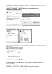
Click on the 'Browse...' Select your monitor is completed. The monitor can be used as is displayed, as shown in sequence. 42 is . in the "Monitor" tab. button, then click on the 'Have disk...' button and then select the appropriate drive F:\Driver (CD-ROM Drive). 8. If the message "Windows needs..." Check the "Browse my computer for your monitor model and click on the 'Next...
Click on the 'Browse...' Select your monitor is completed. The monitor can be used as is displayed, as shown in sequence. 42 is . in the "Monitor" tab. button, then click on the 'Have disk...' button and then select the appropriate drive F:\Driver (CD-ROM Drive). 8. If the message "Windows needs..." Check the "Browse my computer for your monitor model and click on the 'Next...
User's Manual_2436Vwa
Page 48
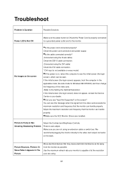
... Setting the Optimal Resolution) If the initial screen (the login screen) does not appear, contact the Service Center or your monitor is capable of the video card. (Refer to the video card output connector on the screen? Check the power cord connection and power supply. Press to the monitor. No images on every model. Is the cable connected correctly? (Connected using the D-sub cable) Check the DB-15 cable connection. (Connected using an extension cable or switch box. Make sure the AOC Monitor Drivers are not using the DVI cable) Check the DVI cable connection. * DVI input...
... Setting the Optimal Resolution) If the initial screen (the login screen) does not appear, contact the Service Center or your monitor is capable of the video card. (Refer to the video card output connector on the screen? Check the power cord connection and power supply. Press to the monitor. No images on every model. Is the cable connected correctly? (Connected using the D-sub cable) Check the DB-15 cable connection. (Connected using an extension cable or switch box. Make sure the AOC Monitor Drivers are not using the DVI cable) Check the DVI cable connection. * DVI input...
User's Manual_2436Vwa
Page 49
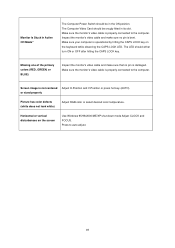
... Adjust H-Position and V-Position or press hot-key (AUTO). The LED should be in its slot. Screen image is bent. Horizontal or vertical disturbances on the keyboard while observing the CAPS LOCK LED. Monitor Is Stuck In Active Off-Mode" The Computer Power Switch should be snugly fitted in the ON position. Missing one of the primary colors (RED, GREEN, or BLUE) Inspect the monitor's video cable and make sure no pin is properly connected...
... Adjust H-Position and V-Position or press hot-key (AUTO). The LED should be in its slot. Screen image is bent. Horizontal or vertical disturbances on the keyboard while observing the CAPS LOCK LED. Monitor Is Stuck In Active Off-Mode" The Computer Power Switch should be snugly fitted in the ON position. Missing one of the primary colors (RED, GREEN, or BLUE) Inspect the monitor's video cable and make sure no pin is properly connected...

User's Manual_2436Vwa
Page 50
Specification General Specification model name 2436Vwa Driving system TFT Color LCD Viewable Image Size 59.8 cm diagonal Pixel pitch LCD Panel Video 0.2715mm(H) x 0.2715mm(V) R, G, B Analog lnterface & Digital Interface Separate Sync. Connector Type 15-pin Mini D-Sub& DVI-D Physical Signal Cable Type Characteristics Dimensions & Weight: Detachable Height (with base) 425.47 mm Width 50 582.14 mm H/V TTL Display Color 16.7M Colors Dot Clock 148.5 MHz Horizontal scan range 30 kHz - 80 kHz Horizontal scan Size(Maximum) 521.28mm Vertical scan...
Specification General Specification model name 2436Vwa Driving system TFT Color LCD Viewable Image Size 59.8 cm diagonal Pixel pitch LCD Panel Video 0.2715mm(H) x 0.2715mm(V) R, G, B Analog lnterface & Digital Interface Separate Sync. Connector Type 15-pin Mini D-Sub& DVI-D Physical Signal Cable Type Characteristics Dimensions & Weight: Detachable Height (with base) 425.47 mm Width 50 582.14 mm H/V TTL Display Color 16.7M Colors Dot Clock 148.5 MHz Horizontal scan range 30 kHz - 80 kHz Horizontal scan Size(Maximum) 521.28mm Vertical scan...
User's Manual_2436Vwa
Page 51
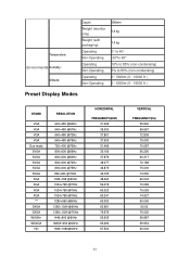
...monitor only) Weight (with packaging) Operating Non-Operating Operating Non-Operating Operating Non-Operating 206mm 5.5 kg 7.0 kg 0°to 40° -20°to 60° 10% to 85% (non-condensing) 5% to 80% (non-condensing) 0~ 3000m (0~ 10000 ft ) 0~ 5000m (0~ 15000 ft ) Preset Display Modes STAND VGA VGA VGA VGA Dos-mode... SVGA SVGA SVGA SVGA SVGA XGA XGA XGA XGA *** SXGA SXGA WXGA+ WSXGA HD RESOLUTION 640×480 ... @60Hz 1920×1080@60Hz HORIZONTAL FREQUENCY(kHZ) 31.469 35.000 ... 65.290 67.500 VERTICAL FREQUENCY(Hz) 59.940 66...
...monitor only) Weight (with packaging) Operating Non-Operating Operating Non-Operating Operating Non-Operating 206mm 5.5 kg 7.0 kg 0°to 40° -20°to 60° 10% to 85% (non-condensing) 5% to 80% (non-condensing) 0~ 3000m (0~ 10000 ft ) 0~ 5000m (0~ 15000 ft ) Preset Display Modes STAND VGA VGA VGA VGA Dos-mode... SVGA SVGA SVGA SVGA SVGA XGA XGA XGA XGA *** SXGA SXGA WXGA+ WSXGA HD RESOLUTION 640×480 ... @60Hz 1920×1080@60Hz HORIZONTAL FREQUENCY(kHZ) 31.469 35.000 ... 65.290 67.500 VERTICAL FREQUENCY(Hz) 59.940 66...
User's Manual_2436Vwa
Page 55
... guarantee that to which can radiate radio frequency energy, and if not installed and used in order to comply with the instructions, may cause harmful interference to provide reasonable protection against harmful interference in a particular installation. Shielded interface cables and AC power cord, if any radio or TV interference caused by turning the equipment off and on a circuit different...
... guarantee that to which can radiate radio frequency energy, and if not installed and used in order to comply with the instructions, may cause harmful interference to provide reasonable protection against harmful interference in a particular installation. Shielded interface cables and AC power cord, if any radio or TV interference caused by turning the equipment off and on a circuit different...
User's Manual_2436Vwa
Page 58
... (excluding Brazil) WARRANTY STATEMENT for AOC Color Monitors Including those Sold within North America as a result of: Shipping or improper installation or maintenance Misuse Neglect Any cause other than ordinary commercial or industrial application Adjustment by non-authorized source Repair, modification, or installation of options or parts by anyone other than an EPI Authorized Service Center Improper environment Excessive or...
... (excluding Brazil) WARRANTY STATEMENT for AOC Color Monitors Including those Sold within North America as a result of: Shipping or improper installation or maintenance Misuse Neglect Any cause other than ordinary commercial or industrial application Adjustment by non-authorized source Repair, modification, or installation of options or parts by anyone other than an EPI Authorized Service Center Improper environment Excessive or...


