Service Guide
Page 20
DT processor) 15W Processor Specification Processor# Athlon 2650e CPU Speed 1.6GHz Cores N/A Bus Speed Mfg Tech 800MHz N/A Cache Size 512KB Package Socket AM2 Acer PN KC.AE002.265 System Board Major Chipsets Item...250 320 120 160 250 320 120 160 250 320 512 512 512 2 2 3 4 2 2 4 4 2 2 3 4 1 1 2 2 1 1 2 2 1 1 2 2 5400 5400 5400 14 Chapter 1 Hardware Specifications and Configurations Processor Item CPU type Clock Speeds L2 Cache Front Side Bus Socket Interface TDP (Thermal Design Power) Specification AMD Athlon 2650e (Acer PN:KC.AE002.265) 1.6 GHz 512KB...
DT processor) 15W Processor Specification Processor# Athlon 2650e CPU Speed 1.6GHz Cores N/A Bus Speed Mfg Tech 800MHz N/A Cache Size 512KB Package Socket AM2 Acer PN KC.AE002.265 System Board Major Chipsets Item...250 320 120 160 250 320 120 160 250 320 512 512 512 2 2 3 4 2 2 4 4 2 2 3 4 1 1 2 2 1 1 2 2 1 1 2 2 5400 5400 5400 14 Chapter 1 Hardware Specifications and Configurations Processor Item CPU type Clock Speeds L2 Cache Front Side Bus Socket Interface TDP (Thermal Design Power) Specification AMD Athlon 2650e (Acer PN:KC.AE002.265) 1.6 GHz 512KB...
Service Guide
Page 28
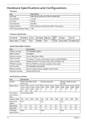
System saves all system states and data onto the disc prior to Disk (S4): Also called Hibernation Mode. System Power Management ACPI mode On Power Management • Working (G0/S0): Individual devices such as the CPU and hard disk may be power managed in this state. • Suspend to RAM (S3): CPU set power down, VGA Suspend, PCMCIA Suspend, Audio Power Down, Hard Disk Power Down, CD-ROM Power Down, and Super I/O Low Power mode. • Save to system shutdown. 22 Chapter 1
System saves all system states and data onto the disc prior to Disk (S4): Also called Hibernation Mode. System Power Management ACPI mode On Power Management • Working (G0/S0): Individual devices such as the CPU and hard disk may be power managed in this state. • Suspend to RAM (S3): CPU set power down, VGA Suspend, PCMCIA Suspend, Audio Power Down, Hard Disk Power Down, CD-ROM Power Down, and Super I/O Low Power mode. • Save to system shutdown. 22 Chapter 1
Service Guide
Page 30
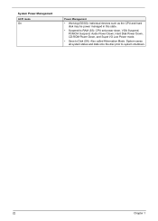
...-ROM drive installed in the system. Serial number of devices installed on the primary IDE channel. Model name of this system. Information Menu ' Parameter CPU Type CPU Speed IDE0 Model Name IDE0 Serial Number IDE1 Model Name IDE1 Serial Number ATAPI Model Name System BIOS Version VGA BIOS Version KBC Version Serial...
...-ROM drive installed in the system. Serial number of devices installed on the primary IDE channel. Model name of this system. Information Menu ' Parameter CPU Type CPU Speed IDE0 Model Name IDE0 Serial Number IDE1 Model Name IDE1 Serial Number ATAPI Model Name System BIOS Version VGA BIOS Version KBC Version Serial...
Service Guide
Page 48
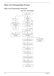
Main Unit Disassembly Process Main Unit Disassembly Flowchart MAIN UNIT DISASSEMBLY MAIN UNIT Hx2 FAN Ax5 CPU HEATSINK MODULE CPU Gx1 LED INDICATORS BOARD MIDDLE COVER Cx2 KEYBOARD Ex4 LCD MODULE Ax1, Ex11 UPPER CASE Cx4 TOUCHPAD BRACKET ASSEMBLY TOUCHPAD BOARD Cx2 DAUGHTER BOARD Ax1 MAINBOARD Cx2 MODEM BOARD Cx2 FINGERPRINT BOARD BLUETOOTH BOARD Dx2 SPEAKER MODULES LOWER CASE 58 Chapter 3
Main Unit Disassembly Process Main Unit Disassembly Flowchart MAIN UNIT DISASSEMBLY MAIN UNIT Hx2 FAN Ax5 CPU HEATSINK MODULE CPU Gx1 LED INDICATORS BOARD MIDDLE COVER Cx2 KEYBOARD Ex4 LCD MODULE Ax1, Ex11 UPPER CASE Cx4 TOUCHPAD BRACKET ASSEMBLY TOUCHPAD BOARD Cx2 DAUGHTER BOARD Ax1 MAINBOARD Cx2 MODEM BOARD Cx2 FINGERPRINT BOARD BLUETOOTH BOARD Dx2 SPEAKER MODULES LOWER CASE 58 Chapter 3
Service Guide
Page 50
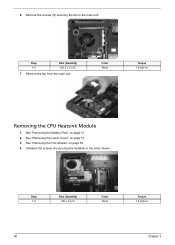
Unfasten the screws (A) securing the heatsink in the order shown. See "Removing the Battery Pack" on page 59. 4. See "Removing the Fan Module" on page 51. 2. Color Black Torque 1.6 kgf-cm Removing the CPU Heatsink Module 1. Remove the screws (H) securing the fan to the main unit. Remove the fan from the main unit. Step 1-5 Size (Quantity) M2 x L4 (5) Color Silver Torque 1.6 kgf-cm 60 Chapter 3 Step 1-2 Size (Quantity) M2.5 x L5 (2) 7. See "Removing the Lower Cover" on page 51. 3. 6.
Unfasten the screws (A) securing the heatsink in the order shown. See "Removing the Battery Pack" on page 59. 4. See "Removing the Fan Module" on page 51. 2. Color Black Torque 1.6 kgf-cm Removing the CPU Heatsink Module 1. Remove the screws (H) securing the fan to the main unit. Remove the fan from the main unit. Step 1-5 Size (Quantity) M2 x L4 (5) Color Silver Torque 1.6 kgf-cm 60 Chapter 3 Step 1-2 Size (Quantity) M2.5 x L5 (2) 7. See "Removing the Lower Cover" on page 51. 3. 6.
Service Guide
Page 51
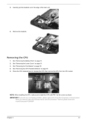
... "Removing the Battery Pack" on page 59. 4. NOTE: When installing the CPU, make sure to release the CPU then remove the CPU from the CPU socket. Thermal grease brand and model:Honeywell PCM45SP. See "Removing the CPU Heatsink Module" on page 51. 3. Removing the CPU 1. See "Removing the Lower Cover" on page 60. 5. Remove the heatsink...
... "Removing the Battery Pack" on page 59. 4. NOTE: When installing the CPU, make sure to release the CPU then remove the CPU from the CPU socket. Thermal grease brand and model:Honeywell PCM45SP. See "Removing the CPU Heatsink Module" on page 51. 3. Removing the CPU 1. See "Removing the Lower Cover" on page 60. 5. Remove the heatsink...
Service Guide
Page 52
See "Removing the Battery Pack" on page 60. 6. See "Removing the CPU Heatsink Module" on page 51. 2. See "Removing the Lower Cover" on page 59. 5. Open the LCD screen all the way to facilitate the easy removal ...
See "Removing the Battery Pack" on page 60. 6. See "Removing the CPU Heatsink Module" on page 51. 2. See "Removing the Lower Cover" on page 59. 5. Open the LCD screen all the way to facilitate the easy removal ...
Service Guide
Page 54
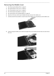
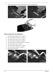
See "Removing the Battery Pack" on page 60. 6. See "Removing the CPU Heatsink Module" on page 51. 2. See "Removing the CPU" on page 51. 3. See "Removing the Lower Cover" on page 61. 7. 5. See "Removing the Keyboard" on page 59. 5. Removing the LCD Module 1. Disconnect the LED cable. 64 Chapter 3 See "Removing the Fan Module" on page 63. 9. See "Removing the Lower Cover" on page 62. 8. See "Removing the Middle Cover" on page 51. 4. Disconnect the keyboard cable from the mainboard to remove the keyboard.
See "Removing the Battery Pack" on page 60. 6. See "Removing the CPU Heatsink Module" on page 51. 2. See "Removing the CPU" on page 51. 3. See "Removing the Lower Cover" on page 61. 7. 5. See "Removing the Keyboard" on page 59. 5. Removing the LCD Module 1. Disconnect the LED cable. 64 Chapter 3 See "Removing the Fan Module" on page 63. 9. See "Removing the Lower Cover" on page 62. 8. See "Removing the Middle Cover" on page 51. 4. Disconnect the keyboard cable from the mainboard to remove the keyboard.
Service Guide
Page 58
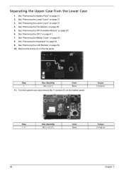
... 62. 8. See "Removing the Middle Cover" on page 51. 4. See "Removing the LCD Module" on page 60. 6. See "Removing the CPU Heatsink Module" on page 64. 10. See "Removing the CPU" on page 63. 9. Separating the Upper Case from the Lower Case 1. See "Removing the Keyboard" on page 61. 7. Torque 1.6 kgf-cm...
... 62. 8. See "Removing the Middle Cover" on page 51. 4. See "Removing the LCD Module" on page 60. 6. See "Removing the CPU Heatsink Module" on page 64. 10. See "Removing the CPU" on page 63. 9. Separating the Upper Case from the Lower Case 1. See "Removing the Keyboard" on page 61. 7. Torque 1.6 kgf-cm...

Service Guide
Page 59
... Silver Torque 1.6 kgf-cm 69 12. See "Removing the Lower Cover" on page 60. 6. See "Removing the CPU Heatsink Module" on page 51. 4. See "Removing the Battery Pack" on page 61. 7. See "Removing the CPU" on page 51. 2. Gently detach the upper case from the Lower Case" on page 68. 11. See...
... Silver Torque 1.6 kgf-cm 69 12. See "Removing the Lower Cover" on page 60. 6. See "Removing the CPU Heatsink Module" on page 51. 4. See "Removing the Battery Pack" on page 61. 7. See "Removing the CPU" on page 51. 2. Gently detach the upper case from the Lower Case" on page 68. 11. See...
Service Guide
Page 61
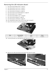
See "Removing the Fan Module" on page 60. 6. See "Removing the CPU Heatsink Module" on page 59. 5. See "Removing the LCD Module" on page 51. 2. Turn the LED board over, then detach the LED cable from the ... "Removing the Lower Cover" on page 62. 8. See "Removing the Middle Cover" on page 51. 3. See "Removing the Keyboard" on page 61. 7. See "Removing the CPU" on page 63. 9. Disconnect the LED board cable from the board, then remove the board. Step 1 Size (Quantity) M2 x L3 (1) Color Silver 12. Removing the...
See "Removing the Fan Module" on page 60. 6. See "Removing the CPU Heatsink Module" on page 59. 5. See "Removing the LCD Module" on page 51. 2. Turn the LED board over, then detach the LED cable from the ... "Removing the Lower Cover" on page 62. 8. See "Removing the Middle Cover" on page 51. 3. See "Removing the Keyboard" on page 61. 7. See "Removing the CPU" on page 63. 9. Disconnect the LED board cable from the board, then remove the board. Step 1 Size (Quantity) M2 x L3 (1) Color Silver 12. Removing the...
Service Guide
Page 62
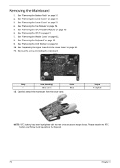
.... Remove the screw (A) holding the mainboard. See "Removing the Lower Cover" on page 61. 7. See "Removing the CPU" on page 51. 4. Carefully detach the mainboard from the Lower Case" on page 62. 8. See "Removing the CPU Heatsink Module" on page 59. 5. See "Removing the Fan Module" on page 60. 6. See "Removing the...
.... Remove the screw (A) holding the mainboard. See "Removing the Lower Cover" on page 61. 7. See "Removing the CPU" on page 51. 4. Carefully detach the mainboard from the Lower Case" on page 62. 8. See "Removing the CPU Heatsink Module" on page 59. 5. See "Removing the Fan Module" on page 60. 6. See "Removing the...

Service Guide
Page 63
See "Removing the Battery Pack" on page 60. 6. See "Removing the CPU Heatsink Module" on page 51. 2. See "Removing the Middle Cover" on page 51. 4. Turn the mainboard over then disconnect the modem cable from the mainboard. .... 5. See "Removing the Fan Module" on page 72. 13. Disconnect the modem board cable from modem board. 14. Removing the Modem Board 1. See "Removing the CPU" on page 61. 7.
See "Removing the Battery Pack" on page 60. 6. See "Removing the CPU Heatsink Module" on page 51. 2. See "Removing the Middle Cover" on page 51. 4. Turn the mainboard over then disconnect the modem cable from the mainboard. .... 5. See "Removing the Fan Module" on page 72. 13. Disconnect the modem board cable from modem board. 14. Removing the Modem Board 1. See "Removing the CPU" on page 61. 7.

Service Guide
Page 64
... screws (C) on page 51. 2. Color Silver Torque 1.6 kgf-cm Removing the Speaker Modules 1. See "Removing the Battery Pack" on the modem board. See "Removing the CPU" on page 68. 11. See "Separating the Upper Case from the mainboard. 12. See "Removing the Lower Cover" on page 63. 9. See "Removing the Keyboard...
... screws (C) on page 51. 2. Color Silver Torque 1.6 kgf-cm Removing the Speaker Modules 1. See "Removing the Battery Pack" on the modem board. See "Removing the CPU" on page 68. 11. See "Separating the Upper Case from the mainboard. 12. See "Removing the Lower Cover" on page 63. 9. See "Removing the Keyboard...

Service Guide
Page 67
....5 x L5 (4) M2.5 x L6 (2) Color Black Black 12. See "Removing the Fan Module" on page 61. 7. See "Removing the CPU" on page 59. 5. See "Removing the Keyboard" on page 60. 6. See "Removing the CPU Heatsink Module" on page 63. 9. Torque 3.0 kgf-cm 3.0 kgf-cm Chapter 3 77 Carefully pry open the LCD bezel and...
....5 x L5 (4) M2.5 x L6 (2) Color Black Black 12. See "Removing the Fan Module" on page 61. 7. See "Removing the CPU" on page 59. 5. See "Removing the Keyboard" on page 60. 6. See "Removing the CPU Heatsink Module" on page 63. 9. Torque 3.0 kgf-cm 3.0 kgf-cm Chapter 3 77 Carefully pry open the LCD bezel and...

Service Guide
Page 68
Removing the Inverter Board 1. See "Removing the Lower Cover" on page 60. 6. See "Removing the CPU Heatsink Module" on page 51. 4. Remove the screw (H) that hold the board to the panel. See "Removing the Middle Cover" on page 64. 10. See "... "Removing the Keyboard" on page 59. 5. See "Removing the Fan Module" on page 63. 9. See "Removing the LCD Bezel" on page 61. 7. See "Removing the CPU" on page 77. 11. Turn the inverter board over. See "Removing the Lower Cover" on page 51. 2. See "Removing the Battery Pack" on page 51. 3.
Removing the Inverter Board 1. See "Removing the Lower Cover" on page 60. 6. See "Removing the CPU Heatsink Module" on page 51. 4. Remove the screw (H) that hold the board to the panel. See "Removing the Middle Cover" on page 64. 10. See "... "Removing the Keyboard" on page 59. 5. See "Removing the Fan Module" on page 63. 9. See "Removing the LCD Bezel" on page 61. 7. See "Removing the CPU" on page 77. 11. Turn the inverter board over. See "Removing the Lower Cover" on page 51. 2. See "Removing the Battery Pack" on page 51. 3.

Service Guide
Page 69
... page 51. 2. See "Removing the LCD Bezel" on page 60. 7. Removing the LCD with Brackets 1. See "Removing the CPU Heatsink Module" on page 77. 12. See "Removing the LCD Module" on page 78. See "Removing the Inverter Board" on page 64. 11. See "Removing ...
... page 51. 2. See "Removing the LCD Bezel" on page 60. 7. Removing the LCD with Brackets 1. See "Removing the CPU Heatsink Module" on page 77. 12. See "Removing the LCD Module" on page 78. See "Removing the Inverter Board" on page 64. 11. See "Removing ...
Service Guide
Page 71
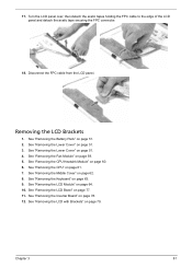
... page 59. 5. See "Removing the Keyboard" on page 79. See "Removing the LCD with Brackets" on page 63. 9. Removing the LCD Brackets 1. See "Removing the CPU" on page 51. 4. See "Removing the Lower Cover" on page 61. 7. See "Removing the Middle Cover" on page 51. 2. See "Removing the Battery Pack" on...
... page 59. 5. See "Removing the Keyboard" on page 79. See "Removing the LCD with Brackets" on page 63. 9. Removing the LCD Brackets 1. See "Removing the CPU" on page 51. 4. See "Removing the Lower Cover" on page 61. 7. See "Removing the Middle Cover" on page 51. 2. See "Removing the Battery Pack" on...
Service Guide
Page 72
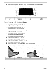
See "Removing the Lower Cover" on page 61. 7. See "Removing the CPU" on page 51. 4. See "Removing the Middle Cover" on page 77. 11. See "Removing the LCD Bezel" on page 62. 8. See "Removing the Battery Pack" ... Chapter 3 See "Removing the LCD with Brackets" on page 60. 6. Remove the eight screws (C) securing the left and right LCD module hinges. See "Removing the CPU Heatsink Module" on page 79. 13. See "Removing the LCD Module" on page 59. 5. Remove the two screws (I) securing the left and right LCD brackets...
See "Removing the Lower Cover" on page 61. 7. See "Removing the CPU" on page 51. 4. See "Removing the Middle Cover" on page 77. 11. See "Removing the LCD Bezel" on page 62. 8. See "Removing the Battery Pack" ... Chapter 3 See "Removing the LCD with Brackets" on page 60. 6. Remove the eight screws (C) securing the left and right LCD module hinges. See "Removing the CPU Heatsink Module" on page 79. 13. See "Removing the LCD Module" on page 59. 5. Remove the two screws (I) securing the left and right LCD brackets...
Service Guide
Page 73
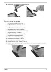
..." on page 64. 11. See "Removing the LCD with Brackets" on page 51. 5. See "Removing the Lower Cover" on page 79. 14. See "Removing the CPU Heatsink Module" on page 51. 2. Chapter 3 83 See "Removing the Battery Pack" on page 60. 7. Remove the left and right hinges from the LCD back... cover. See "Removing the Middle Cover" on page 61. 8. See "Removing the CPU" on page 62. 9. See "Removing the Fan Module" on page 63. 10. See "Removing the Keyboard" on page 59. 6. Removing the Antennas 1.
..." on page 64. 11. See "Removing the LCD with Brackets" on page 51. 5. See "Removing the Lower Cover" on page 79. 14. See "Removing the CPU Heatsink Module" on page 51. 2. Chapter 3 83 See "Removing the Battery Pack" on page 60. 7. Remove the left and right hinges from the LCD back... cover. See "Removing the Middle Cover" on page 61. 8. See "Removing the CPU" on page 62. 9. See "Removing the Fan Module" on page 63. 10. See "Removing the Keyboard" on page 59. 6. Removing the Antennas 1.


