
Service Guide
Page 63
.... 2. Turn the mainboard over then disconnect the modem cable from the mainboard. 13. See "Removing the Battery Pack" on page 72. See "Removing the Middle Cover" on page 63. 9. Chapter 3 73 See "Removing the Keyboard" on page 62. 8. See "Separating the Upper Case from the Lower Case" on page 51. 3. ...Removing the Modem Board 1. See "Removing the Lower Cover" on page 68. 11. See "Removing the Fan Module" on page 61. 7. See "Removing the CPU" on page 59. 5. See "Removing the...
.... 2. Turn the mainboard over then disconnect the modem cable from the mainboard. 13. See "Removing the Battery Pack" on page 72. See "Removing the Middle Cover" on page 63. 9. Chapter 3 73 See "Removing the Keyboard" on page 62. 8. See "Separating the Upper Case from the Lower Case" on page 51. 3. ...Removing the Modem Board 1. See "Removing the Lower Cover" on page 68. 11. See "Removing the Fan Module" on page 61. 7. See "Removing the CPU" on page 59. 5. See "Removing the...

Service Guide
Page 69
...2P cable on page 61. 8. Removing the LCD with Brackets 1. See "Removing the CPU" on the inverter board. 14. See "Removing the LCD Bezel" on page 51. 2. Chapter 3 79 See "Removing the Battery Pack" on page 77. 12. See "Removing the Lower Cover" on page 51. 3. 4. 13. ...See "Removing the Lower Cover" on page 51. 5. See "Removing the Inverter...
...2P cable on page 61. 8. Removing the LCD with Brackets 1. See "Removing the CPU" on the inverter board. 14. See "Removing the LCD Bezel" on page 51. 2. Chapter 3 79 See "Removing the Battery Pack" on page 77. 12. See "Removing the Lower Cover" on page 51. 3. 4. 13. ...See "Removing the Lower Cover" on page 51. 5. See "Removing the Inverter...

Service Guide
Page 70
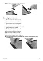
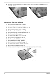
Detach the CCD board cable from the back cover. 80 Chapter 3 Detach the LCD with the brackets from the CCD board, then remove the board. 14. Step 1~2 Size (Quantity) M2.5 x L5 (2) Color Silver 15. Carefully detach the cables from the latches on the LCD bracket as shown. Torque 2.5 kgf-cm 16. 13. Remove the two screws (I) securing the left and right LCD brackets to the LCD back cover.
Detach the CCD board cable from the back cover. 80 Chapter 3 Detach the LCD with the brackets from the CCD board, then remove the board. 14. Step 1~2 Size (Quantity) M2.5 x L5 (2) Color Silver 15. Carefully detach the cables from the latches on the LCD bracket as shown. Torque 2.5 kgf-cm 16. 13. Remove the two screws (I) securing the left and right LCD brackets to the LCD back cover.
Service Guide
Page 72
.... 6. See "Removing the Lower Cover" on page 61. 7. See "Removing the CPU" on page 51. 3. See "Removing the LCD Bezel" on page 78. 12. See "Removing the Inverter Board" on page 77. 11. See "Removing the LCD Module" on page 81. 14. See "Removing the LCD Brackets" on page 64. 10.... See "Removing the Middle Cover" on page 51. 2. Torque 1.6 kgf-cm Step 1~2 Size (Quantity) M2.5 x L5 (2) Color Black Torque ...
.... 6. See "Removing the Lower Cover" on page 61. 7. See "Removing the CPU" on page 51. 3. See "Removing the LCD Bezel" on page 78. 12. See "Removing the Inverter Board" on page 77. 11. See "Removing the LCD Module" on page 81. 14. See "Removing the LCD Brackets" on page 64. 10.... See "Removing the Middle Cover" on page 51. 2. Torque 1.6 kgf-cm Step 1~2 Size (Quantity) M2.5 x L5 (2) Color Black Torque ...
Service Guide
Page 73
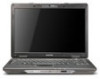
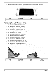
... Heatsink Module" on page 51. 3. 4. See "Removing the Keyboard" on page 62. 9. See "Removing the Middle Cover" on page 63. 10. See "Removing the LCD Module" on page 79. 14. See "Removing the LCD with Brackets" on page 64. 11. See "Removing the Battery Pack" on page 78. 13. See "Removing the... then carefully remove the antenna. See "Removing the Fan Module" on page 61. 8. Chapter 3 83 Remove the left and right hinges from the LCD back cover. See "Removing the Lower Cover" on page 77. 12. See "Removing the LCD Bezel" on page 51. 5. Removing the Antennas 1.
... Heatsink Module" on page 51. 3. 4. See "Removing the Keyboard" on page 62. 9. See "Removing the Middle Cover" on page 63. 10. See "Removing the LCD Module" on page 79. 14. See "Removing the LCD with Brackets" on page 64. 11. See "Removing the Battery Pack" on page 78. 13. See "Removing the... then carefully remove the antenna. See "Removing the Fan Module" on page 61. 8. Chapter 3 83 Remove the left and right hinges from the LCD back cover. See "Removing the Lower Cover" on page 77. 12. See "Removing the LCD Bezel" on page 51. 5. Removing the Antennas 1.
Service Guide
Page 74
... the Keyboard" on page 51. 5. See "Removing the LCD Module" on page 51. 3. See "Removing the Lower Cover" on page 64. 11. See "Removing the LCD Bezel" on page 61. 8. See "Removing the CPU" on page 77. 12. See "Removing the LCD with Brackets" on page 51. 2. 15. Detach the ...gasket tape holding the left antenna in place, remove the antenna bracket, then carefully remove the antenna. See "Removing the Battery Pack" on page 79. 14...
... the Keyboard" on page 51. 5. See "Removing the LCD Module" on page 51. 3. See "Removing the Lower Cover" on page 64. 11. See "Removing the LCD Bezel" on page 61. 8. See "Removing the CPU" on page 77. 12. See "Removing the LCD with Brackets" on page 51. 2. 15. Detach the ...gasket tape holding the left antenna in place, remove the antenna bracket, then carefully remove the antenna. See "Removing the Battery Pack" on page 79. 14...


