
English Manual
Page 3
... product. 3 ICON assumes no responsibility for normal use a barbell longer than seven feet with pre-existing health problems. Read all users of the weight bench are performing bench press exercises, squat exercises or toe raise exercises, your physician. It is designed to catch the barbell if you feel pain or dizziness at any...
... product. 3 ICON assumes no responsibility for normal use a barbell longer than seven feet with pre-existing health problems. Read all users of the weight bench are performing bench press exercises, squat exercises or toe raise exercises, your physician. It is designed to catch the barbell if you feel pain or dizziness at any...
English Manual
Page 7
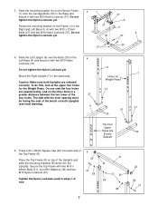
... are spaced evenly, and on the Frame (1) to the Right and Left Base (5, 4) with two M10 x 72mm Bolts (27) and two M10 Nylon Locknuts (37). Press a 50 x 50mm Square Cap (20) into the Uprights. Caution: Make sure both Uprights (see inset drawing). 4 6 7 Holes for the Weight Rests. Secure the Top ... Locknuts (37). Mount the Right Upright (7) in steps 1-5 now. 5 20 31 38 7 8 B 37 B 38 38 20 38 31 3. Slide the mounting bracket (A) on the Bench Frame 3 1 (1) onto the Carriage Bolts (30) in the 4 Left Base (4) and secure it with the even spacing must be facing the seat of the...
... are spaced evenly, and on the Frame (1) to the Right and Left Base (5, 4) with two M10 x 72mm Bolts (27) and two M10 Nylon Locknuts (37). Press a 50 x 50mm Square Cap (20) into the Uprights. Caution: Make sure both Uprights (see inset drawing). 4 6 7 Holes for the Weight Rests. Secure the Top ... Locknuts (37). Mount the Right Upright (7) in steps 1-5 now. 5 20 31 38 7 8 B 37 B 38 38 20 38 31 3. Slide the mounting bracket (A) on the Bench Frame 3 1 (1) onto the Carriage Bolts (30) in the 4 Left Base (4) and secure it with the even spacing must be facing the seat of the...
English Manual
Page 8
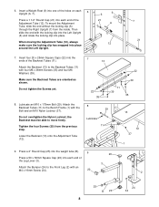
... weight tube (B). 9 20 Press a 50 x 50mm Square Cap (20) into place. When moving the Adjustment Tube (12), always make sure the locking clip has snapped into the ends of the Backrest Tubes (11). Lubricate an M10 x 175mm Bolt (29). the Backrest must be able to the Bench Frame (1) with the locking... clip into the Left Upright (6) and rotate the locking clip into each end of the Adjustment Tube (12). Then slide the end with the Bolt and an M10 Nylon Locknut (37). Press a 1 1/2" Round Cap (21) into one of ...
... weight tube (B). 9 20 Press a 50 x 50mm Square Cap (20) into place. When moving the Adjustment Tube (12), always make sure the locking clip has snapped into the ends of the Backrest Tubes (11). Lubricate an M10 x 175mm Bolt (29). the Backrest must be able to the Bench Frame (1) with the locking... clip into the Left Upright (6) and rotate the locking clip into each end of the Adjustment Tube (12). Then slide the end with the Bolt and an M10 Nylon Locknut (37). Press a 1 1/2" Round Cap (21) into one of ...
English Manual
Page 9
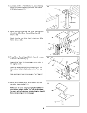
... of all remain- Make sure all parts are properly tightened before you use of the Seat (14) to the Bench Frame (1) with 13 two M6 x 16mm Screws (33). The use the weight bench. ing parts will be explained in the Leg Lever (3). Insert the remaining Pad Tube through each of the three... Pad Tubes (17). Slide two Foam Pads (18) onto each of the holes in Adjusting the Weight 15 Bench beginning on the Front Leg (2). Lubricate an M10 x 72mm Bolt (27). Press 19mm Round Caps (23) into the ends of each Pad Tube (17). 12 18 23 33 32 39 17...
... of all remain- Make sure all parts are properly tightened before you use of the Seat (14) to the Bench Frame (1) with 13 two M6 x 16mm Screws (33). The use the weight bench. ing parts will be explained in the Leg Lever (3). Insert the remaining Pad Tube through each of the three... Pad Tubes (17). Slide two Foam Pads (18) onto each of the holes in Adjusting the Weight 15 Bench beginning on the Front Leg (2). Lubricate an M10 x 72mm Bolt (27). Press 19mm Round Caps (23) into the ends of each Pad Tube (17). 12 18 23 33 32 39 17...


