
English Manual
Page 1
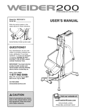
IMPORTANT: You must note the product model number and serial number (see the drawing above for future reference. WESY2037.0 Serial No. Serial Number Decal (under seat) QUESTIONS? MST Sat. 8 a.m.-4 p.m. MST ON THE WEB: www.weiderservice.com CAUTION Read all precautions and instructions in the space above ) before using this manual for future reference. Visit our website at www.proform.com new products, prizes, fitness tips, and much more ! Write the serial number in this manual before contacting us: CALL TOLL-FREE: 1-877-992-5999 Mon.-Fri. 6 a.m.-6 p.m. If you have questions, ...
IMPORTANT: You must note the product model number and serial number (see the drawing above for future reference. WESY2037.0 Serial No. Serial Number Decal (under seat) QUESTIONS? MST Sat. 8 a.m.-4 p.m. MST ON THE WEB: www.weiderservice.com CAUTION Read all precautions and instructions in the space above ) before using this manual for future reference. Visit our website at www.proform.com new products, prizes, fitness tips, and much more ! Write the serial number in this manual before contacting us: CALL TOLL-FREE: 1-877-992-5999 Mon.-Fri. 6 a.m.-6 p.m. If you have questions, ...
English Manual
Page 2
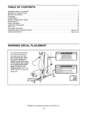
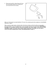
WEIDER is missing or illegible, call the telephone number on the front cover of ICON IP, Inc. 2 Apply the decal in the locations shown. If a decal ...
WEIDER is missing or illegible, call the telephone number on the front cover of ICON IP, Inc. 2 Apply the decal in the locations shown. If a decal ...
English Manual
Page 3
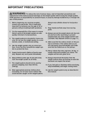
It is the responsibility of the owner to ensure that all users of the weight system are on page 11). 11. The weight system is especially important for home use the weight system in a commercial, rental, or institutional setting. 4. Keep hands and feet away from the weight system when performing an exercise that could become caught on a level surface. Keep children under age 12 and pets away from the weight system at all times. The weight system should not be used by or through the use of the weight system (see LOCKING THE WEIGHT STACK on the pulleys. 12. Do not use ...
It is the responsibility of the owner to ensure that all users of the weight system are on page 11). 11. The weight system is especially important for home use the weight system in a commercial, rental, or institutional setting. 4. Keep hands and feet away from the weight system when performing an exercise that could become caught on a level surface. Keep children under age 12 and pets away from the weight system at all times. The weight system should not be used by or through the use of the weight system (see LOCKING THE WEIGHT STACK on the pulleys. 12. Do not use ...
English Manual
Page 4
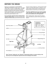
... labeled. If you , note the product model number and serial number before using the weight system. To avoid a registration fee for selecting the versatile WEIDER® PRECISION SYSTEM 200 weight system. High Pulley Station Lat Bar Backrest Curl Pad Right Side Leg Lever Front Stabilizer ASSEMBLED DIMENSIONS: Height: 76 in. (193 cm) Width...
... labeled. If you , note the product model number and serial number before using the weight system. To avoid a registration fee for selecting the versatile WEIDER® PRECISION SYSTEM 200 weight system. High Pulley Station Lat Bar Backrest Curl Pad Right Side Leg Lever Front Stabilizer ASSEMBLED DIMENSIONS: Height: 76 in. (193 cm) Width...
English Manual
Page 5
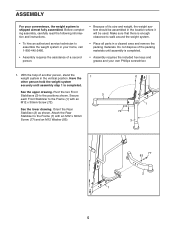
Before completing assembly, carefully read the following information and instructions. • Because of its size and weight, the weight system should be used. See the upper drawing. Orient the Rear Stabilizer (2) as shown. Secure 3 each Front Stabilizer to the positions shown. Pivot the two Front Stabilizers (3) to the Frame (1) with an M12 x 60mm Screw (77) and an M12 Washer (83). 1 72 3 1 5 77 83 2 Attach the Rear Stabilizer to assemble the weight system in your home, call 1-800-445-2480. • Place all parts in a cleared area and remove the packing materials. ...
Before completing assembly, carefully read the following information and instructions. • Because of its size and weight, the weight system should be used. See the upper drawing. Orient the Rear Stabilizer (2) as shown. Secure 3 each Front Stabilizer to the positions shown. Pivot the two Front Stabilizers (3) to the Frame (1) with an M12 x 60mm Screw (77) and an M12 Washer (83). 1 72 3 1 5 77 83 2 Attach the Rear Stabilizer to assemble the weight system in your home, call 1-800-445-2480. • Place all parts in a cleared area and remove the packing materials. ...

English Manual
Page 6
Make sure that the barrel of the Bolt Set is inserted through both sides of pegs on the Seat Frame. Next, slide the Seat Frame (4) downward onto a set of the bracket on the Frame (1). Apply some of the included grease to the Seat Frame (4) with the Bolt Set. Attach the Leg Lever (5) to the barrel of the Backrest (21). Locate the two Mounting Pegs (not shown) on the Frame (1), and then slide the Backrest downward. Bracket 21 1 Bracket 4 68 5 68 Grease 6 Insert the Mounting Pegs into the indicated brackets on 2 the back of an M10 x 65mm Bolt Set (68). 2.
Make sure that the barrel of the Bolt Set is inserted through both sides of pegs on the Seat Frame. Next, slide the Seat Frame (4) downward onto a set of the bracket on the Frame (1). Apply some of the included grease to the Seat Frame (4) with the Bolt Set. Attach the Leg Lever (5) to the barrel of the Backrest (21). Locate the two Mounting Pegs (not shown) on the Frame (1), and then slide the Backrest downward. Bracket 21 1 Bracket 4 68 5 68 Grease 6 Insert the Mounting Pegs into the indicated brackets on 2 the back of an M10 x 65mm Bolt Set (68). 2.
English Manual
Page 7
3. Before using the weight system, pull each cable a few times to make sure that all parts are not properly installed, they may be explained in the cables, you will need to the 23 Curl Post (6) with the two Screws. 6 67 Make sure that the cables move smoothly, find and correct the problem. IMPORTANT: If the cables are properly tightened. Remove the two M6 x 16mm Screws (67) from 3 the Curl Pad (23). If there is used. Attach the Curl Pad to remove the slack by tightening the cables. See MAINTENANCE on page 14 for proper cable routing. If one of the remaining parts ...
3. Before using the weight system, pull each cable a few times to make sure that all parts are not properly installed, they may be explained in the cables, you will need to the 23 Curl Post (6) with the two Screws. 6 67 Make sure that the cables move smoothly, find and correct the problem. IMPORTANT: If the cables are properly tightened. Remove the two M6 x 16mm Screws (67) from 3 the Curl Pad (23). If there is used. Attach the Curl Pad to remove the slack by tightening the cables. See MAINTENANCE on page 14 for proper cable routing. If one of the remaining parts ...
English Manual
Page 8
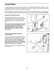
ADJUSTMENT This section explains how to the High Cable (30) in the correct starting position for important information about how to the cables and pulleys, the amount of the Weight Pin touches the weight stack. Also, refer to the accompanying exercise guide to see the correct form for a variety of resistance at each weight station. 53 16 ATTACHING ACCESSORIES TO THE HIGH PULLEY STATION Attach the Lat Bar (42) to the High Cable (30) at each time the weight system is in the same way. 30 43 42 43 44 91 8 Use the WEIGHT RESISTANCE CHART on page 15 for the exercise to ...
ADJUSTMENT This section explains how to the High Cable (30) in the correct starting position for important information about how to the cables and pulleys, the amount of the Weight Pin touches the weight stack. Also, refer to the accompanying exercise guide to see the correct form for a variety of resistance at each weight station. 53 16 ATTACHING ACCESSORIES TO THE HIGH PULLEY STATION Attach the Lat Bar (42) to the High Cable (30) at each time the weight system is in the same way. 30 43 42 43 44 91 8 Use the WEIGHT RESISTANCE CHART on page 15 for the exercise to ...

English Manual
Page 9
Attach the Handle Strap (91) to the Low Cable (31) at the low pulley station with the low pulley station, first remove the seat (see ATTACHING THE SEAT below). When the Press Arms (7, 8) are not in the correct starting position for the exercise to be performed. For some exercises, attach a Chain (44) between the Lat Bar and the Cable so that the Lat Bar is not in the same way. Adjust the length of pegs on the Frame (1). When the Seat (22) is in use the Press Arms (7, 8) pull them away from the weight system. 91 42 31 43 43 44 22 4 1 USING THE PRESS ARMS To use , raise ...
Attach the Handle Strap (91) to the Low Cable (31) at the low pulley station with the low pulley station, first remove the seat (see ATTACHING THE SEAT below). When the Press Arms (7, 8) are not in the correct starting position for the exercise to be performed. For some exercises, attach a Chain (44) between the Lat Bar and the Cable so that the Lat Bar is not in the same way. Adjust the length of pegs on the Frame (1). When the Seat (22) is in use the Press Arms (7, 8) pull them away from the weight system. 91 42 31 43 43 44 22 4 1 USING THE PRESS ARMS To use , raise ...
English Manual
Page 10
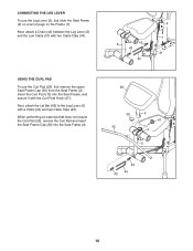
Next, attach the Lat Bar (42) to the Leg Lever (5) with two Cable Clips (43). Next, attach a Chain (44) between the Leg Lever (5) and the Low Cable (31) with a Chain (44) and two Cable Clips (43). USING THE CURL PAD To use the Leg Lever (5), first slide the Seat Frame (4) on a set of pegs on the Frame (1). Insert the Curl Post (13) into the Seat Frame (4). 5 43 43 44 4 1 31 23 35 42 6 47 4 5 43 44 43 10 When performing an exercise that does not require the Curl Pad (23), remove the Curl Pad and insert the Seat Frame Cap (35) into the Seat Frame, and secure it with the ...
Next, attach the Lat Bar (42) to the Leg Lever (5) with two Cable Clips (43). Next, attach a Chain (44) between the Leg Lever (5) and the Low Cable (31) with a Chain (44) and two Cable Clips (43). USING THE CURL PAD To use the Leg Lever (5), first slide the Seat Frame (4) on a set of pegs on the Frame (1). Insert the Curl Post (13) into the Seat Frame (4). 5 43 43 44 4 1 31 23 35 42 6 47 4 5 43 44 43 10 When performing an exercise that does not require the Curl Pad (23), remove the Curl Pad and insert the Seat Frame Cap (35) into the Seat Frame, and secure it with the ...

English Manual
Page 11
LOCKING THE WEIGHT STACK Lock the weight stack by inserting the Lock Pin (54) into one of the Weight Guides (19) and securing the Lock (55) onto the Lock Pin. 19 55 54 11
LOCKING THE WEIGHT STACK Lock the weight stack by inserting the Lock Pin (54) into one of the Weight Guides (19) and securing the Lock (55) onto the Lock Pin. 19 55 54 11

English Manual
Page 12
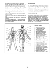
weights. WEIGHT 1 2 3 4 5 6 7 8 PRESS ARM (lbs.) 44 64 83 104 123 145 170 199 HIGH PULLEY (lbs.) 24 31 41 57 66 78 86 99 LEG LEVER (lbs.) 40 64 83 104 123 145 170 199 LOW PULLEY (lbs.) 48 69 99 118 139 160 185 222 Note: 1 lb. = 2.2 kg 12 Note: The actual resistance at each station may vary due to differences in the left column refer to the 10-lb. The numbers in individual weights as well as friction between the cables, pulleys, and weight guides. WEIGHT RESISTANCE CHART The chart below shows the approximate weight resistance at each exercise station.
weights. WEIGHT 1 2 3 4 5 6 7 8 PRESS ARM (lbs.) 44 64 83 104 123 145 170 199 HIGH PULLEY (lbs.) 24 31 41 57 66 78 86 99 LEG LEVER (lbs.) 40 64 83 104 123 145 170 199 LOW PULLEY (lbs.) 48 69 99 118 139 160 185 222 Note: 1 lb. = 2.2 kg 12 Note: The actual resistance at each station may vary due to differences in the left column refer to the 10-lb. The numbers in individual weights as well as friction between the cables, pulleys, and weight guides. WEIGHT RESISTANCE CHART The chart below shows the approximate weight resistance at each exercise station.
English Manual
Page 13
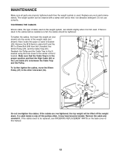
To tighten the cables, first insert the weight pin (not shown) into the center of the Ubracket. Next, locate the upper or lower U-bracket (18). Remove the M10 Nylon Locknut (57) and the M10 x 50mm Bolt (64) from the U-bracket, the 90mm Pulley (27), and the Cable Trap (51). Make sure that the High Cable (30) or the Low Cable (31) is used . Remove the cable and reinstall it may have become twisted. Reattach the Pulley and the Cable Trap to the Ubracket using the hole closer to the center of the weight stack (not shown). If the cables are properly tightened each time the ...
To tighten the cables, first insert the weight pin (not shown) into the center of the Ubracket. Next, locate the upper or lower U-bracket (18). Remove the M10 Nylon Locknut (57) and the M10 x 50mm Bolt (64) from the U-bracket, the 90mm Pulley (27), and the Cable Trap (51). Make sure that the High Cable (30) or the Low Cable (31) is used . Remove the cable and reinstall it may have become twisted. Reattach the Pulley and the Cable Trap to the Ubracket using the hole closer to the center of the weight stack (not shown). If the cables are properly tightened each time the ...

English Manual
Page 14
Make sure that cable. If the cables are assembled correctly. High Cable (30) Length: 110 in. (280 cm) 4 1 2 Press Cable (29) Length: 64 in. (163 cm) 1 Low Cable (31) Length: 101 in each drawing show the proper route for that the cable traps do not touch or bind the cables. CABLE DIAGRAM The diagram below shows the proper routing of the cables. The numbers in . (256 cm) 2 3 3 5 5 4 2 1 4 3 14 Use the diagram to make sure that the cables and the cable traps are not assembled correctly, the weight system will not function properly and damage may occur.
Make sure that cable. If the cables are assembled correctly. High Cable (30) Length: 110 in. (280 cm) 4 1 2 Press Cable (29) Length: 64 in. (163 cm) 1 Low Cable (31) Length: 101 in each drawing show the proper route for that the cable traps do not touch or bind the cables. CABLE DIAGRAM The diagram below shows the proper routing of the cables. The numbers in . (256 cm) 2 3 3 5 5 4 2 1 4 3 14 Use the diagram to make sure that the cables and the cable traps are not assembled correctly, the weight system will not function properly and damage may occur.
English Manual
Page 15
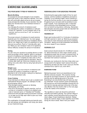
You can adjust the intensity level of an individual exercise in any exercise program. Progress at your own pace and be followed by at least one sit-up . WARMING UP The proper amount of resistance for 1 minute after each set . Rest for each set. Work your muscles by changing the number of repetitions or sets per- Weight Loss To lose weight, use a low amount of resistance and increase the number of repetitions in each repetition and inhale during the return stroke. Select exercises for you. This requires moving only the appropriate parts of the body. Never hold ...
You can adjust the intensity level of an individual exercise in any exercise program. Progress at your own pace and be followed by at least one sit-up . WARMING UP The proper amount of resistance for 1 minute after each set . Rest for each set. Work your muscles by changing the number of repetitions or sets per- Weight Loss To lose weight, use a low amount of resistance and increase the number of repetitions in each repetition and inhale during the return stroke. Select exercises for you. This requires moving only the appropriate parts of the body. Never hold ...
English Manual
Page 16
Exhale during the return stroke. The ideal resting periods are: • Rest for three minutes after each set for a weight loss workout. Write the date, the exercises performed, the resistance used, and the numbers of arm) S. Sternomastoid (neck) B. Brachioradials (forearm) F. Anterior Deltoid (shoulder) M. Adductor (inner thigh) O. Trapezius (upper back) P. Triceps (back of sets and repetitions completed. Latissimus Dorsi (mid back) T. Gluteus Medius (hip) V. Plan to spend the first couple of weeks familiarizing yourself with 5 to 10 minutes of each exercise. STAYING ...
Exhale during the return stroke. The ideal resting periods are: • Rest for three minutes after each set for a weight loss workout. Write the date, the exercises performed, the resistance used, and the numbers of arm) S. Sternomastoid (neck) B. Brachioradials (forearm) F. Anterior Deltoid (shoulder) M. Adductor (inner thigh) O. Trapezius (upper back) P. Triceps (back of sets and repetitions completed. Latissimus Dorsi (mid back) T. Gluteus Medius (hip) V. Plan to spend the first couple of weeks familiarizing yourself with 5 to 10 minutes of each exercise. STAYING ...
English Manual
Page 17
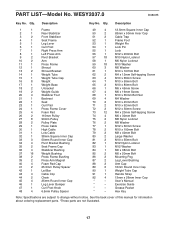
WESY2037.0 R0807B Key No. Qty. Description 1 1 Frame 2 1 Rear Stabilizer 3 2 Front Stabilizer 4 1 Seat Frame 5 1 Leg Lever 6 1 Curl Post 7 1 Right Press Arm 8 1 Left Press Arm 9 2 Pivot Bracket 10 2 Arm 11 1 Press Frame 12 1 Shroud 13 2 Shroud Bracket 14 1 Weight Tube 15 1 Weight Tube Cap 16 8 Weight 17 1 Weight Base 18 2 U-bracket 19 2 Weight Guide 20 4 Stabilizer Foot 21 1 Backrest 22 1 Seat 23 1 Curl Pad 24 1 Press Frame Cover 25 4 Foam Pad 26 2 115mm Pulley 27 8 90mm Pulley 28 2 Pulley Plate 29 1 Press...
WESY2037.0 R0807B Key No. Qty. Description 1 1 Frame 2 1 Rear Stabilizer 3 2 Front Stabilizer 4 1 Seat Frame 5 1 Leg Lever 6 1 Curl Post 7 1 Right Press Arm 8 1 Left Press Arm 9 2 Pivot Bracket 10 2 Arm 11 1 Press Frame 12 1 Shroud 13 2 Shroud Bracket 14 1 Weight Tube 15 1 Weight Tube Cap 16 8 Weight 17 1 Weight Base 18 2 U-bracket 19 2 Weight Guide 20 4 Stabilizer Foot 21 1 Backrest 22 1 Seat 23 1 Curl Pad 24 1 Press Frame Cover 25 4 Foam Pad 26 2 115mm Pulley 27 8 90mm Pulley 28 2 Pulley Plate 29 1 Press...
English Manual
Page 18
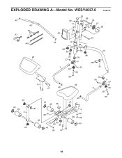
WESY2037.0 R0807B 45 42 43 91 44 24 45 82 11 57 33 56 62 28 27 28 61 10 59 23 6 88 39 73 57 7 34 63 88 34 9 73 64 59 10 39 65 22 67 45 34 64 9 57 8 34 59 65 45 87 40 47 25 35 40 25 5 87 68 4 60 25 66 25 73 46 69 35 40 33 40 68 67 18 EXPLODED DRAWING A-Model No.
WESY2037.0 R0807B 45 42 43 91 44 24 45 82 11 57 33 56 62 28 27 28 61 10 59 23 6 88 39 73 57 7 34 63 88 34 9 73 64 59 10 39 65 22 67 45 34 64 9 57 8 34 59 65 45 87 40 47 25 35 40 25 5 87 68 4 60 25 66 25 73 46 69 35 40 33 40 68 67 18 EXPLODED DRAWING A-Model No.
English Manual
Page 19
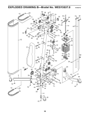
EXPLODED DRAWING B-Model No. WESY2037.0 R0807B 20 73 13 13 30 12 31 3 92 80 38 57 38 27 80 27 79 57 49 57 59 49 50 59 26 59 58 57 74 50 30 15 59 70 64 49 27 59 59 63 49 59 63 21 29 32 1 85 86 60 85 60 86 84 71 37 70 51 27 57 18 64 29 57 31 73 18 69 17 64 51 27 27 26 57 89 59 41 57 36 78 74 48 73 76 75 57 59 14 19 90 16 53 16 73 55 69 54 20 83 77 20 41 57 59 48 81 36 52 59 92 72 72 69 71 73 2 73 36 3 20 73 19
EXPLODED DRAWING B-Model No. WESY2037.0 R0807B 20 73 13 13 30 12 31 3 92 80 38 57 38 27 80 27 79 57 49 57 59 49 50 59 26 59 58 57 74 50 30 15 59 70 64 49 27 59 59 63 49 59 63 21 29 32 1 85 86 60 85 60 86 84 71 37 70 51 27 57 18 64 29 57 31 73 18 69 17 64 51 27 27 26 57 89 59 41 57 36 78 74 48 73 76 75 57 59 14 19 90 16 53 16 73 55 69 54 20 83 77 20 41 57 59 48 81 36 52 59 92 72 72 69 71 73 2 73 36 3 20 73 19
English Manual
Page 20
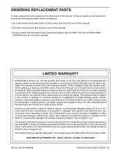
ORDERING REPLACEMENT PARTS To order replacement parts, please see the PART LIST and the EXPLODED DRAWING near the end of this manual) LIMITED WARRANTY ICON Health & Fitness, Inc. (ICON) warrants this product to be free from the date of whatsoever nature. All repairs for which vary from the service center will be pre-authorized by ICON. If the product is authorized by ICON. The warranty extended hereunder is in lieu of any and all other rights which warranty claims are made must be responsible for indirect, special or consequential damages arising out of or in ...
ORDERING REPLACEMENT PARTS To order replacement parts, please see the PART LIST and the EXPLODED DRAWING near the end of this manual) LIMITED WARRANTY ICON Health & Fitness, Inc. (ICON) warrants this product to be free from the date of whatsoever nature. All repairs for which vary from the service center will be pre-authorized by ICON. If the product is authorized by ICON. The warranty extended hereunder is in lieu of any and all other rights which warranty claims are made must be responsible for indirect, special or consequential damages arising out of or in ...