
English Manual
Page 1
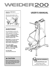
Serial Number Decal (under seat) QUESTIONS? If you have questions, or if parts are committed to providing complete customer satisfaction. please contact Customer Care. MST ON THE WEB: www.weiderservice.com CAUTION Read all precautions and instructions in the space above ) before using this manual for future reference. Write the serial number in this manual before contacting us: CALL TOLL-FREE: 1-877-992...
Serial Number Decal (under seat) QUESTIONS? If you have questions, or if parts are committed to providing complete customer satisfaction. please contact Customer Care. MST ON THE WEB: www.weiderservice.com CAUTION Read all precautions and instructions in the space above ) before using this manual for future reference. Write the serial number in this manual before contacting us: CALL TOLL-FREE: 1-877-992...
English Manual
Page 2
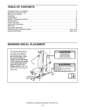
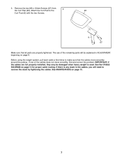
WEIDER is missing or illegible, call the telephone number on the front cover of ICON IP, Inc. 2 Apply the decal in the locations shown. Note: The decals may not be shown at actual size. TABLE OF CONTENTS WARNING DECAL PLACEMENT 2 IMPORTANT PRECAUTIONS 3 BEFORE YOU BEGIN 4 ASSEMBLY 5 ADJUSTMENT 8 WEIGHT RESISTANCE CHART 12 MAINTENANCE 13 CABLE DIAGRAM 14 EXERCISE GUIDELINES 15 PART LIST 17 EXPLODED DRAWING 18 ORDERING REPLACEMENT PARTS Back Cover LIMITED WARRANTY Back...
WEIDER is missing or illegible, call the telephone number on the front cover of ICON IP, Inc. 2 Apply the decal in the locations shown. Note: The decals may not be shown at actual size. TABLE OF CONTENTS WARNING DECAL PLACEMENT 2 IMPORTANT PRECAUTIONS 3 BEFORE YOU BEGIN 4 ASSEMBLY 5 ADJUSTMENT 8 WEIGHT RESISTANCE CHART 12 MAINTENANCE 13 CABLE DIAGRAM 14 EXERCISE GUIDELINES 15 PART LIST 17 EXPLODED DRAWING 18 ORDERING REPLACEMENT PARTS Back Cover LIMITED WARRANTY Back...
English Manual
Page 3
... the arms, leg lever, lat bar, or handle strap while weights are exercising, stop immediately and begin cooling down. 8. Before beginning any worn parts immediately. Inspect and properly tighten all precautions. 3. Always wear athletic shoes for home use the weight system in this product. 1. If the cables bind as described in a commercial, rental, or institutional setting. 4. Use the weight system only on the pulleys at all users of the weight...
... the arms, leg lever, lat bar, or handle strap while weights are exercising, stop immediately and begin cooling down. 8. Before beginning any worn parts immediately. Inspect and properly tighten all precautions. 3. Always wear athletic shoes for home use the weight system in this product. 1. If the cables bind as described in a commercial, rental, or institutional setting. 4. Use the weight system only on the pulleys at all users of the weight...
English Manual
Page 4
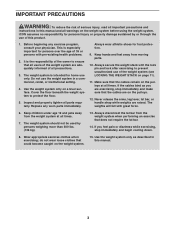
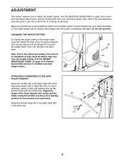
... Pulley Station Lat Bar Backrest Curl Pad Right Side Leg Lever Front Stabilizer ASSEMBLED DIMENSIONS: Height: 76 in. (193 cm) Width: 36 in. (92 cm) Depth: 51 in the manual. 4 To help you to right and left side" are shown on the front cover of this manual carefully before contacting us assist you, note the product model number and serial number before using the weight...
... Pulley Station Lat Bar Backrest Curl Pad Right Side Leg Lever Front Stabilizer ASSEMBLED DIMENSIONS: Height: 76 in. (193 cm) Width: 36 in. (92 cm) Depth: 51 in the manual. 4 To help you to right and left side" are shown on the front cover of this manual carefully before contacting us assist you, note the product model number and serial number before using the weight...
English Manual
Page 5
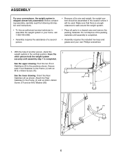
... hold the weight system securely until assembly is completed. Attach the Rear Stabilizer to the positions shown. Do not dispose of the packing materials until assembly step 1 is completed. • Assembly requires the assistance of a second person. • Assembly requires the included hex keys and grease and your home, call 1-800-445-2480. • Place all parts in a cleared area and remove the...
... hold the weight system securely until assembly is completed. Attach the Rear Stabilizer to the positions shown. Do not dispose of the packing materials until assembly step 1 is completed. • Assembly requires the assistance of a second person. • Assembly requires the included hex keys and grease and your home, call 1-800-445-2480. • Place all parts in a cleared area and remove the...

English Manual
Page 6
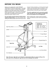
Insert the Mounting Pegs into the indicated brackets on the Seat Frame. Make sure that the barrel of the Bolt Set is inserted through both sides of the bracket on the Frame (1), and then slide the Backrest downward. Apply some of the included grease to the Seat Frame (4) with the Bolt Set. Next, slide the Seat Frame (4) downward onto a set of pegs on 2 the back of an M10 x 65mm Bolt Set (68). Attach the Leg Lever (5) to the barrel of the Backrest (21). Bracket 21 1 Bracket 4 68 5 68 Grease 6 Locate the two Mounting Pegs (not shown) on the Frame (1). 2.
Insert the Mounting Pegs into the indicated brackets on the Seat Frame. Make sure that the barrel of the Bolt Set is inserted through both sides of the bracket on the Frame (1), and then slide the Backrest downward. Apply some of the included grease to the Seat Frame (4) with the Bolt Set. Next, slide the Seat Frame (4) downward onto a set of pegs on 2 the back of an M10 x 65mm Bolt Set (68). Attach the Leg Lever (5) to the barrel of the Backrest (21). Bracket 21 1 Bracket 4 68 5 68 Grease 6 Locate the two Mounting Pegs (not shown) on the Frame (1). 2.
English Manual
Page 7
... Make sure that the cables move smoothly, find and correct the problem. See MAINTENANCE on page 14 for proper cable routing. If one of the remaining parts will be damaged when heavy weight is any slack in ADJUSTMENT, beginning on page 8. If there is used. The use of the cables does not move smoothly around the pulleys. Remove the two M6 x 16mm Screws (67) from 3 the...
... Make sure that the cables move smoothly, find and correct the problem. See MAINTENANCE on page 14 for proper cable routing. If one of the remaining parts will be damaged when heavy weight is any slack in ADJUSTMENT, beginning on page 8. If there is used. The use of the cables does not move smoothly around the pulleys. Remove the two M6 x 16mm Screws (67) from 3 the...
English Manual
Page 8
... exercise guide to see the correct form for important information about how to the cables and pulleys, the amount of resistance at each time the weight system is in the same way. 30 43 42 43 44 91 8 Use the WEIGHT RESISTANCE CHART on page 15 for a variety of the Weight Pin touches the weight stack. Attach the Handle Strap (91) to adjust the weight system. CHANGING THE WEIGHT SETTING To change the weight setting...
... exercise guide to see the correct form for important information about how to the cables and pulleys, the amount of resistance at each time the weight system is in the same way. 30 43 42 43 44 91 8 Use the WEIGHT RESISTANCE CHART on page 15 for a variety of the Weight Pin touches the weight stack. Attach the Handle Strap (91) to adjust the weight system. CHANGING THE WEIGHT SETTING To change the weight setting...

English Manual
Page 9
... pulley station with two Cable Clips. Adjust the length of pegs on the Frame (1). When the Press Arms (7, 8) are not in the correct starting position for the exercise to the Low Cable (31) in use, set of the Chain between the Lat Bar and the Cable with a Cable Clip (43). ATTACHING THE SEAT To use accessories with the low pulley station, first remove the seat (see ATTACHING THE SEAT below). For some exercises, attach...
... pulley station with two Cable Clips. Adjust the length of pegs on the Frame (1). When the Press Arms (7, 8) are not in the correct starting position for the exercise to the Low Cable (31) in use, set of the Chain between the Lat Bar and the Cable with a Cable Clip (43). ATTACHING THE SEAT To use accessories with the low pulley station, first remove the seat (see ATTACHING THE SEAT below). For some exercises, attach...
English Manual
Page 10
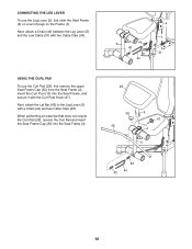
...use the Leg Lever (5), first slide the Seat Frame (4) on a set of pegs on the Frame (1). Next, attach the Lat Bar (42) to the Leg Lever (5) with two Cable Clips (43). Next, attach a Chain (44) between the Leg Lever (5) and the Low Cable (31) with a Chain (44) and two Cable Clips (43). Insert the Curl Post (13) into the Seat...10 CONNECTING THE LEG LEVER To use the Curl Pad (23), first remove the upper Seat Frame Cap (35) from the Seat Frame (4). When performing an exercise that does not require the Curl Pad (23), remove the Curl Pad and insert the Seat Frame Cap (35) into the Seat Frame...
...use the Leg Lever (5), first slide the Seat Frame (4) on a set of pegs on the Frame (1). Next, attach the Lat Bar (42) to the Leg Lever (5) with two Cable Clips (43). Next, attach a Chain (44) between the Leg Lever (5) and the Low Cable (31) with a Chain (44) and two Cable Clips (43). Insert the Curl Post (13) into the Seat...10 CONNECTING THE LEG LEVER To use the Curl Pad (23), first remove the upper Seat Frame Cap (35) from the Seat Frame (4). When performing an exercise that does not require the Curl Pad (23), remove the Curl Pad and insert the Seat Frame Cap (35) into the Seat Frame...

English Manual
Page 11
LOCKING THE WEIGHT STACK Lock the weight stack by inserting the Lock Pin (54) into one of the Weight Guides (19) and securing the Lock (55) onto the Lock Pin. 19 55 54 11
LOCKING THE WEIGHT STACK Lock the weight stack by inserting the Lock Pin (54) into one of the Weight Guides (19) and securing the Lock (55) onto the Lock Pin. 19 55 54 11

English Manual
Page 12
weights. Note: The actual resistance at each station may vary due to the 10-lb. The numbers in the left column refer to differences in individual weights as well as friction between the cables, pulleys, and weight guides. WEIGHT RESISTANCE CHART The chart below shows the approximate weight resistance at each exercise station. WEIGHT 1 2 3 4 5 6 7 8 PRESS ARM (lbs.) 44 64 83 104 123 145 170 199 HIGH PULLEY (lbs.) 24 31 41 57 66 78 86 99 LEG LEVER (lbs.) 40 64 83 104 123 145 170 199 LOW PULLEY (lbs.) 48 69 99 118 139 160 185 222 Note: 1 lb. = 2.2 kg 12
weights. Note: The actual resistance at each station may vary due to the 10-lb. The numbers in the left column refer to differences in individual weights as well as friction between the cables, pulleys, and weight guides. WEIGHT RESISTANCE CHART The chart below shows the approximate weight resistance at each exercise station. WEIGHT 1 2 3 4 5 6 7 8 PRESS ARM (lbs.) 44 64 83 104 123 145 170 199 HIGH PULLEY (lbs.) 24 31 41 57 66 78 86 99 LEG LEVER (lbs.) 40 64 83 104 123 145 170 199 LOW PULLEY (lbs.) 48 69 99 118 139 160 185 222 Note: 1 lb. = 2.2 kg 12
English Manual
Page 13
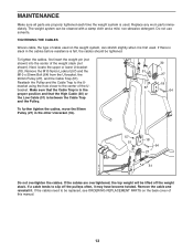
... weight pin (not shown) into the center of the Ubracket. Remove the M10 Nylon Locknut (57) and the M10 x 50mm Bolt (64) from the U-bracket, the 90mm Pulley (27), and the Cable Trap (51). If the cables need to slip off the weight stack. TIGHTENING THE CABLES Woven cable, the type of this manual. 13 Do not use solvents. Next, locate the upper or lower U-bracket (18). Replace...
... weight pin (not shown) into the center of the Ubracket. Remove the M10 Nylon Locknut (57) and the M10 x 50mm Bolt (64) from the U-bracket, the 90mm Pulley (27), and the Cable Trap (51). If the cables need to slip off the weight stack. TIGHTENING THE CABLES Woven cable, the type of this manual. 13 Do not use solvents. Next, locate the upper or lower U-bracket (18). Replace...

English Manual
Page 14
Make sure that the cables and the cable traps are not assembled correctly, the weight system will not function properly and damage may occur. The numbers in . (256 cm) 2 3 3 5 5 4 2 1 4 3 14 If the cables are assembled correctly. High Cable (30) Length: 110 in. (280 cm) 4 1 2 Press Cable (29) Length: 64 in. (163 cm) 1 Low Cable (31) Length: 101 in each drawing show the proper route for that cable. CABLE DIAGRAM The diagram below shows the proper routing of the cables. Use the diagram to make sure that the cable traps do not touch or bind the cables.
Make sure that the cables and the cable traps are not assembled correctly, the weight system will not function properly and damage may occur. The numbers in . (256 cm) 2 3 3 5 5 4 2 1 4 3 14 If the cables are assembled correctly. High Cable (30) Length: 110 in. (280 cm) 4 1 2 Press Cable (29) Length: 64 in. (163 cm) 1 Low Cable (31) Length: 101 in each drawing show the proper route for that cable. CABLE DIAGRAM The diagram below shows the proper routing of the cables. Use the diagram to make sure that the cable traps do not touch or bind the cables.
English Manual
Page 15
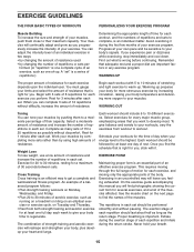
... amount of resistance used • by changing the number of the muscles. Schedule your body time to your breath. 15 Exercising in each exercise depends upon the individual user. On the exercise guide accompanying this manual you will leave you experience pain or dizziness while exercising, stop immediately and cool down. See the muscle chart on Tuesday and Thursday. • Rest from workout to 20...
... amount of resistance used • by changing the number of the muscles. Schedule your body time to your breath. 15 Exercising in each exercise depends upon the individual user. On the exercise guide accompanying this manual you will leave you experience pain or dizziness while exercising, stop immediately and cool down. See the muscle chart on Tuesday and Thursday. • Rest from workout to 20...
English Manual
Page 16
... your everyday life. Rest for a toning work- Stretching at the end of stretching. Pectoralis Major (chest) C. Gluteus Maximus (buttocks) W. Exhale during the exertion stage of sets and repetitions completed. Include stretches for a weight loss workout. Move slowly as you can without pausing. Write the date, the exercises performed, the resistance used, and the numbers of each repetition and inhale during...
... your everyday life. Rest for a toning work- Stretching at the end of stretching. Pectoralis Major (chest) C. Gluteus Maximus (buttocks) W. Exhale during the exertion stage of sets and repetitions completed. Include stretches for a weight loss workout. Move slowly as you can without pausing. Write the date, the exercises performed, the resistance used, and the numbers of each repetition and inhale during...
English Manual
Page 17
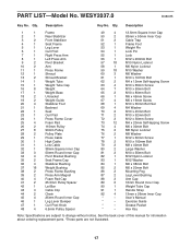
See the back cover of this manual for information about ordering replacement parts. *These parts are subject to change without notice. PART LIST-Model No. Description 1 1 Frame 2 1 Rear Stabilizer 3 2 Front Stabilizer 4 1 Seat Frame 5 1 Leg Lever 6 1 Curl Post 7 1 Right Press Arm 8 1 Left Press Arm 9 2 Pivot Bracket 10 2 Arm 11 1 Press Frame 12 1 Shroud 13 2 Shroud Bracket 14 1 Weight Tube 15 1 Weight Tube Cap 16 8 Weight 17 1 Weight Base 18 2 U-bracket 19 2 Weight Guide 20 4 Stabilizer Foot 21...
See the back cover of this manual for information about ordering replacement parts. *These parts are subject to change without notice. PART LIST-Model No. Description 1 1 Frame 2 1 Rear Stabilizer 3 2 Front Stabilizer 4 1 Seat Frame 5 1 Leg Lever 6 1 Curl Post 7 1 Right Press Arm 8 1 Left Press Arm 9 2 Pivot Bracket 10 2 Arm 11 1 Press Frame 12 1 Shroud 13 2 Shroud Bracket 14 1 Weight Tube 15 1 Weight Tube Cap 16 8 Weight 17 1 Weight Base 18 2 U-bracket 19 2 Weight Guide 20 4 Stabilizer Foot 21...
English Manual
Page 18
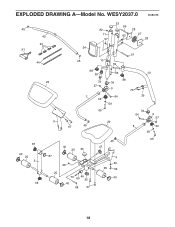
EXPLODED DRAWING A-Model No. WESY2037.0 R0807B 45 42 43 91 44 24 45 82 11 57 33 56 62 28 27 28 61 10 59 23 6 88 39 73 57 7 34 63 88 34 9 73 64 59 10 39 65 22 67 45 34 64 9 57 8 34 59 65 45 87 40 47 25 35 40 25 5 87 68 4 60 25 66 25 73 46 69 35 40 33 40 68 67 18
EXPLODED DRAWING A-Model No. WESY2037.0 R0807B 45 42 43 91 44 24 45 82 11 57 33 56 62 28 27 28 61 10 59 23 6 88 39 73 57 7 34 63 88 34 9 73 64 59 10 39 65 22 67 45 34 64 9 57 8 34 59 65 45 87 40 47 25 35 40 25 5 87 68 4 60 25 66 25 73 46 69 35 40 33 40 68 67 18
English Manual
Page 19
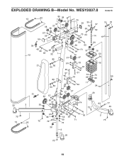
WESY2037.0 R0807B 20 73 13 13 30 12 31 3 92 80 38 57 38 27 80 27 79 57 49 57 59 49 50 59 26 59 58 57 74 50 30 15 59 70 64 49 27 59 59 63 49 59 63 21 29 32 1 85 86 60 85 60 86 84 71 37 70 51 27 57 18 64 29 57 31 73 18 69 17 64 51 27 27 26 57 89 59 41 57 36 78 74 48 73 76 75 57 59 14 19 90 16 53 16 73 55 69 54 20 83 77 20 41 57 59 48 81 36 52 59 92 72 72 69 71 73 2 73 36 3 20 73 19 EXPLODED DRAWING B-Model No.
WESY2037.0 R0807B 20 73 13 13 30 12 31 3 92 80 38 57 38 27 80 27 79 57 49 57 59 49 50 59 26 59 58 57 74 50 30 15 59 70 64 49 27 59 59 63 49 59 63 21 29 32 1 85 86 60 85 60 86 84 71 37 70 51 27 57 18 64 29 57 31 73 18 69 17 64 51 27 27 26 57 89 59 41 57 36 78 74 48 73 76 75 57 59 14 19 90 16 53 16 73 55 69 54 20 83 77 20 41 57 59 48 81 36 52 59 92 72 72 69 71 73 2 73 36 3 20 73 19 EXPLODED DRAWING B-Model No.
English Manual
Page 20
... other warranty beyond that specifically set forth herein. Accordingly, the above is in connection with respect to you . This warranty gives you , be pre-authorized by ICON. ICON's obligation under normal use and service conditions, for commercial or rental purposes; ORDERING REPLACEMENT PARTS To order replacement parts, please see the PART LIST and the EXPLODED DRAWING near the end of this manual) LIMITED WARRANTY ICON Health & Fitness, Inc. (ICON) warrants this manual. You...
... other warranty beyond that specifically set forth herein. Accordingly, the above is in connection with respect to you . This warranty gives you , be pre-authorized by ICON. ICON's obligation under normal use and service conditions, for commercial or rental purposes; ORDERING REPLACEMENT PARTS To order replacement parts, please see the PART LIST and the EXPLODED DRAWING near the end of this manual) LIMITED WARRANTY ICON Health & Fitness, Inc. (ICON) warrants this manual. You...


