
Uk Manual
Page 1
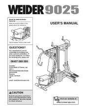
... Industrial Estate Revie Road Beeston Leeds, LS118JG UK email: [email protected] CAUTION Read all precautions and instructions in the space above for future reference. Write the serial number in this manual before using this manual for reference. Serial Number Decal (under seat) QUESTIONS? Save this equipment. As a manufacturer, we are missing parts, please call: 08457 089 009 Or write: ICON Health & Fitness, Ltd.
... Industrial Estate Revie Road Beeston Leeds, LS118JG UK email: [email protected] CAUTION Read all precautions and instructions in the space above for future reference. Write the serial number in this manual before using this manual for reference. Serial Number Decal (under seat) QUESTIONS? Save this equipment. As a manufacturer, we are missing parts, please call: 08457 089 009 Or write: ICON Health & Fitness, Ltd.
Uk Manual
Page 2
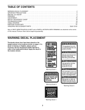
... DECAL PLACEMENT 2 IMPORTANT PRECAUTIONS 3 BEFORE YOU BEGIN 4 ASSEMBLY 5 ADJUSTMENT 16 WEIGHT RESISTANCE CHART 18 TROUBLESHOOTING 19 CABLE DIAGRAM 20 EXERCISE GUIDELINES 21 ORDERING REPLACEMENT PARTS Back Cover Note: A PART IDENTIFICATION CHART and a PARTS LIST/EXPLODED DRAWING are attached at the centre of this manual. Warning Decal 2 Warning Decal 4 Warning Decal 3 2 Apply the decal in the locations shown on page 4. Remove them before beginning assembly. If a decal is missing or illegible, please...
... DECAL PLACEMENT 2 IMPORTANT PRECAUTIONS 3 BEFORE YOU BEGIN 4 ASSEMBLY 5 ADJUSTMENT 16 WEIGHT RESISTANCE CHART 18 TROUBLESHOOTING 19 CABLE DIAGRAM 20 EXERCISE GUIDELINES 21 ORDERING REPLACEMENT PARTS Back Cover Note: A PART IDENTIFICATION CHART and a PARTS LIST/EXPLODED DRAWING are attached at the centre of this manual. Warning Decal 2 Warning Decal 4 Warning Decal 3 2 Apply the decal in the locations shown on page 4. Remove them before beginning assembly. If a decal is missing or illegible, please...
Uk Manual
Page 3
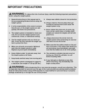
...-existing health problems. Read all instructions before using . Always disconnect the lat bar from the weight system when performing an exercise that does not use . Keep hands and feet away from the weight system at any worn parts immediately. 9. WARNING: Before beginning this manual and in this or any commercial, rental, or institutional setting. 4. Cover the floor beneath the weight system to support a a maximum user weight of the pulleys...
...-existing health problems. Read all instructions before using . Always disconnect the lat bar from the weight system when performing an exercise that does not use . Keep hands and feet away from the weight system at any worn parts immediately. 9. WARNING: Before beginning this manual and in this or any commercial, rental, or institutional setting. 4. Cover the floor beneath the weight system to support a a maximum user weight of the pulleys...
Uk Manual
Page 4
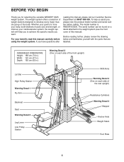
... the body. The model number is to the weight system (see the front cover of this manual). If you for selecting the versatile WEIDER® 9025 weight system. The serial number can be found on each side of the front upright) Lat Bar High Pulley Station Warning Decal 1 Fly Arm Backrest Seat Warning Decal 2 Leg Lever Low Pulley Station VKR Arms Warning Decal 4 (One on a decal attached to tone your body, build...
... the body. The model number is to the weight system (see the front cover of this manual). If you for selecting the versatile WEIDER® 9025 weight system. The serial number can be found on each side of the front upright) Lat Bar High Pulley Station Warning Decal 1 Fly Arm Backrest Seat Warning Decal 2 Leg Lever Low Pulley Station VKR Arms Warning Decal 4 (One on a decal attached to tone your body, build...
Uk Manual
Page 5
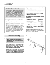
...; As you assemble the weight system, make sure all parts as you have a socket set, a set of time, assembly will go smoothly. Most people find that you assemble them, unless instructed to the Stabiliser (2) with two M4 Washers (75) and two M4 x 16mm Selftapping Screws (74). Important: Wait until assembly is completed. • Tighten all parts are required for assembly: • two adjustable spanners...
...; As you assemble the weight system, make sure all parts as you have a socket set, a set of time, assembly will go smoothly. Most people find that you assemble them, unless instructed to the Stabiliser (2) with two M4 Washers (75) and two M4 x 16mm Selftapping Screws (74). Important: Wait until assembly is completed. • Tighten all parts are required for assembly: • two adjustable spanners...

Uk Manual
Page 8
... 37 Hook 14 Arm Assembly 8 8. The teeth on the inside of the Rear Upright (3). Repeat this step with an M4 x 16mm Self-tapping Screw (74). Attach the Butterfly Frame (11) to the Pedal with the Bolt and an M10 Nylon Locknut (72). Lubricate the pedal axles on the left side of the Pedal. Slide a 16mm Round Bushing (40) and a Resistance Cylinder (37) onto...
... 37 Hook 14 Arm Assembly 8 8. The teeth on the inside of the Rear Upright (3). Repeat this step with an M4 x 16mm Self-tapping Screw (74). Attach the Butterfly Frame (11) to the Pedal with the Bolt and an M10 Nylon Locknut (72). Lubricate the pedal axles on the left side of the Pedal. Slide a 16mm Round Bushing (40) and a Resistance Cylinder (37) onto...

Uk Manual
Page 9
...not overtighten the Locknut; 72 23 Lubricate 60 10 71 11 the Fly Arm must be able to the indi- Press a 25mm Dome Inner Cap (25) into the Right and Left VKR Arms (12, 13). Repeat this step with the Bolt, two M10 Washers (71), ...Attach the Right Fly Arm (9) to pivot easily. 72 Assemble the Left Fly Arm (10) in the same manner. 10. Attach an Arm Handle (24) to pivot easily. Attach the Right and Left VKR Arms (12, 13) to the Right Fly Arm (9) 9 with soapy water. Attach a Cable Pivot (58) to the Rear Upright (3) with two M8 x 20mm Button Head Bolts (84). Wet the lower...
...not overtighten the Locknut; 72 23 Lubricate 60 10 71 11 the Fly Arm must be able to the indi- Press a 25mm Dome Inner Cap (25) into the Right and Left VKR Arms (12, 13). Repeat this step with the Bolt, two M10 Washers (71), ...Attach the Right Fly Arm (9) to pivot easily. 72 Assemble the Left Fly Arm (10) in the same manner. 10. Attach an Arm Handle (24) to pivot easily. Attach the Right and Left VKR Arms (12, 13) to the Right Fly Arm (9) 9 with soapy water. Attach a Cable Pivot (58) to the Rear Upright (3) with two M8 x 20mm Button Head Bolts (84). Wet the lower...

Uk Manual
Page 10
... Handle (42). Wrap the Butterfly Cable (55) over a "V"-pulley 16 (47). Wrap the Butterfly Cable (55) over a "V"-pulley 14 (47). Attach the "V"-pulley and a Cable Trap (48) to the Front Upright (4) with the Right VKR Arm (12). 41 42 43 80 71 72 13 12 71 105 Cable Assembly 13 13. Repeat this step with an M10 x 60mm Bolt (95) and an M10...
... Handle (42). Wrap the Butterfly Cable (55) over a "V"-pulley 16 (47). Wrap the Butterfly Cable (55) over a "V"-pulley 14 (47). Attach the "V"-pulley and a Cable Trap (48) to the Front Upright (4) with the Right VKR Arm (12). 41 42 43 80 71 72 13 12 71 105 Cable Assembly 13 13. Repeat this step with an M10 x 60mm Bolt (95) and an M10...

Uk Manual
Page 11
... 4 71 72 94 89 19. 17. Attach the Short Cable (94) to 18 the Front Upright (4) with an M8 Nylon Locknut (73). Route the Cable up through the Top Frame (6) and over a 90mm Pulley (46). Locate the Short Cable (94). Locate the High Cable (57). Attach the Pulley inside the Top Frame with an M10 x 68mm Bolt (87), two M10 Washers (71), two...
... 4 71 72 94 89 19. 17. Attach the Short Cable (94) to 18 the Front Upright (4) with an M8 Nylon Locknut (73). Route the Cable up through the Top Frame (6) and over a 90mm Pulley (46). Locate the Short Cable (94). Locate the High Cable (57). Attach the Pulley inside the Top Frame with an M10 x 68mm Bolt (87), two M10 Washers (71), two...

Uk Manual
Page 14
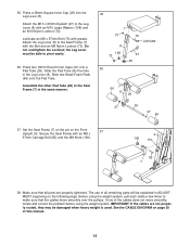
...tighten the Locknut yet. Attach the Seat Plate (28) to the Rear Upright 32 (3) with an M6 x 50mm Carriage Bolt (78), an M6 Washer (69), and an M6 Nylon Locknut (90) as shown. Seat Assembly 31. Attach the Seat (62) to the Front Upright (3) with two M6 x 16mm Screws (76). Attach the Backrest (61) to the Seat ...14 Attach a VKR Arm Pad (64) to the Seat Frame (7) with an M6 x 53mm Screw (70) and an M6 Washer (69). Repeat this step with two M6 x 53mm Screws (70) and two M6 Washers (69). Press a 38mm Square Inner Cap (29) into the Seat Frame (7). Next, attach the Seat to the Left VKR Arm ...
...tighten the Locknut yet. Attach the Seat Plate (28) to the Rear Upright 32 (3) with an M6 x 50mm Carriage Bolt (78), an M6 Washer (69), and an M6 Nylon Locknut (90) as shown. Seat Assembly 31. Attach the Seat (62) to the Front Upright (3) with two M6 x 16mm Screws (76). Attach the Backrest (61) to the Seat ...14 Attach a VKR Arm Pad (64) to the Seat Frame (7) with an M6 x 53mm Screw (70) and an M6 Washer (69). Repeat this step with two M6 x 53mm Screws (70) and two M6 Washers (69). Press a 38mm Square Inner Cap (29) into the Seat Frame (7). Next, attach the Seat to the Left VKR Arm ...
Uk Manual
Page 15
... grease. Before using the weight system. Set the Seat Frame (7) on the pin on page 20 of all parts are not properly routed, they may be able to the Seat Frame (7) with an M10 Large Washer (108) and an M10 Nylon Locknut (72). See the CABLE DIAGRAM on the Front 37 Upright (4). Assemble the other Pad Tube (26) to the Leg Lever (8) with the Bolt...
... grease. Before using the weight system. Set the Seat Frame (7) on the pin on page 20 of all parts are not properly routed, they may be able to the Seat Frame (7) with an M10 Large Washer (108) and an M10 Nylon Locknut (72). See the CABLE DIAGRAM on the Front 37 Upright (4). Assemble the other Pad Tube (26) to the Leg Lever (8) with the Bolt...

Uk Manual
Page 16
... 20 the WEIGHT RESISTANCE CHART on page 18 to find the actual amount of the Weight Guides (5). LOCKING THE WEIGHT STACK To prevent unauthorised use the weight system again. 5 22 21 ATTACHING THE ACCESSORIES TO A PULLEY STATION Attach the Lat Bar (101) to the Low Cable (not shown) in the correct starting position for the exercise to the cables and pulleys, the actual amount of the Weights (16). For...
... 20 the WEIGHT RESISTANCE CHART on page 18 to find the actual amount of the Weight Guides (5). LOCKING THE WEIGHT STACK To prevent unauthorised use the weight system again. 5 22 21 ATTACHING THE ACCESSORIES TO A PULLEY STATION Attach the Lat Bar (101) to the Low Cable (not shown) in the correct starting position for the exercise to the cables and pulleys, the actual amount of the Weights (16). For...

Uk Manual
Page 17
... Cable Clips (68). ATTACHING THE LEG LEVER To use . Make sure that the "L"-pins (100) are fully inserted into the same set of holes before touching them. 17 106 4 7 82 Pin 8 97 68 99 56 68 37 14 15 Next, remove the M8 Knob (106) and M8 x 67mm Carriage Bolt (82) from the Rear Upright (3), the greater the resistance will be removed. CHANGING THE STEPPING RESISTANCE To change...
... Cable Clips (68). ATTACHING THE LEG LEVER To use . Make sure that the "L"-pins (100) are fully inserted into the same set of holes before touching them. 17 106 4 7 82 Pin 8 97 68 99 56 68 37 14 15 Next, remove the M8 Knob (106) and M8 x 67mm Carriage Bolt (82) from the Rear Upright (3), the greater the resistance will be removed. CHANGING THE STEPPING RESISTANCE To change...

Uk Manual
Page 18
WEIGHT RESISTANCE CHART The chart below shows the approximate weight resistance at each exercise station. The other numbers refer to the 6 lb. top weight. Note: The actual resistance at each station may vary due to differences in individual weight plates as well as friction between the cables, pulleys, and weight guides. WEIGHT Top 1 2 3 4 5 6 7 8 9 HIGH PULLEY PRESS ARM (lbs.) (lbs.) 13 25 31 44 47 67 64 81 77 101 87...
WEIGHT RESISTANCE CHART The chart below shows the approximate weight resistance at each exercise station. The other numbers refer to the 6 lb. top weight. Note: The actual resistance at each station may vary due to differences in individual weight plates as well as friction between the cables, pulleys, and weight guides. WEIGHT Top 1 2 3 4 5 6 7 8 9 HIGH PULLEY PRESS ARM (lbs.) (lbs.) 13 25 31 44 47 67 64 81 77 101 87...
Uk Manual
Page 19
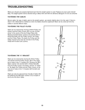
... M10 x 53mm Bolt (88) from the Pulley Covers, the Pulley, and the "U"-bracket. Re-attach the Pulley and the Pulley Covers to the new set of holes in the "U"-bracket (53). Replace any worn parts immediately. The weight system can be removed from the Short Cable (94) by tightening the M8 Nylon Locknut (73) a couple of holes in the cables before resistance is felt, the cables should be...
... M10 x 53mm Bolt (88) from the Pulley Covers, the Pulley, and the "U"-bracket. Re-attach the Pulley and the Pulley Covers to the new set of holes in the "U"-bracket (53). Replace any worn parts immediately. The weight system can be removed from the Short Cable (94) by tightening the M8 Nylon Locknut (73) a couple of holes in the cables before resistance is felt, the cables should be...
Uk Manual
Page 21
... close to their capacity. WEIGHT LOSS To lose weight, use a low amount of resistance and increase the number of repetitions in an uncontrolled manner will reshape and strengthen your body, plus develop your heart and lungs. CROSS TRAINING Cross training is an essential part of the body. Find out what is important. Each workout should be followed by using high amounts of resistance. EXERCISE FORM Maintaining proper form is an...
... close to their capacity. WEIGHT LOSS To lose weight, use a low amount of resistance and increase the number of repetitions in an uncontrolled manner will reshape and strengthen your body, plus develop your heart and lungs. CROSS TRAINING Cross training is an essential part of the body. Find out what is important. Each workout should be followed by using high amounts of resistance. EXERCISE FORM Maintaining proper form is an...
Uk Manual
Page 22
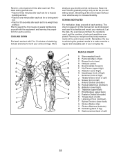
... each set for a muscle building workout. • Rest for one minute after each set for a weight loss workout. Include stretches for both your weight and key body measurements at the end of arm) D. Move slowly ...chest) C. Posterior Deltoid (shoulder) R. COOLING DOWN End each workout with the equipment and learning the proper form for each stretch gradually and go only as far as you can be photocopied and used , and the numbers of calf) 22 List the date, the exercises performed, the resistance used to make exercise a regular and enjoyable part of calf) K. Remember, the key...
... each set for a muscle building workout. • Rest for one minute after each set for a weight loss workout. Include stretches for both your weight and key body measurements at the end of arm) D. Move slowly ...chest) C. Posterior Deltoid (shoulder) R. COOLING DOWN End each workout with the equipment and learning the proper form for each stretch gradually and go only as far as you can be photocopied and used , and the numbers of calf) 22 List the date, the exercises performed, the resistance used to make exercise a regular and enjoyable part of calf) K. Remember, the key...
Uk Manual
Page 24
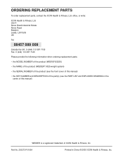
...this manual) WEIDER is a registered trademark of the part(s) (see the PART LIST and EXPLODED DRAWING in China © 2003 ICON Health & Fitness, Inc. office, or write: ICON Health & Fitness, ...information when ordering replacement parts: • the MODEL NUMBER of the product (WEEVSY20230) • the NAME of the product (WEIDER® 9025 weight system) • the SERIAL NUMBER of the product (see the front cover of this manual) • the KEY NUMBER and DESCRIPTION of ICON Health & Fitness, Inc. ORDERING REPLACEMENT PARTS To order replacement parts, contact the ICON Health & Fitness...
...this manual) WEIDER is a registered trademark of the part(s) (see the PART LIST and EXPLODED DRAWING in China © 2003 ICON Health & Fitness, Inc. office, or write: ICON Health & Fitness, ...information when ordering replacement parts: • the MODEL NUMBER of the product (WEEVSY20230) • the NAME of the product (WEIDER® 9025 weight system) • the SERIAL NUMBER of the product (see the front cover of this manual) • the KEY NUMBER and DESCRIPTION of ICON Health & Fitness, Inc. ORDERING REPLACEMENT PARTS To order replacement parts, contact the ICON Health & Fitness...
Uk Manual
Page 26
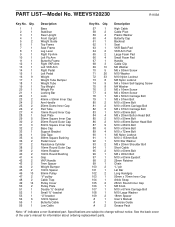
... Button Head Bolt M10 x 68mm Bolt M10 x 53mm Bolt M10 x 72mm Bolt M6 Nylon Locknut M10 x 153mm Bolt M10 Star Washer M8 x 20mm Shoulder Bolt Short Cable M10 x 60mm Bolt M8 x 45mm Bolt M10 x 63mm Eyebolt 25mm Retainer Chain "L"-pin Lat Bar Long Handgrip 50mm x 70mm Inner Cap Ankle Strap 25mm Round Inner Cap M8 Knob M10 x 67mm Carriage Bolt M10 Large Washer 18mm Spacer User's Manual Exercise Guide Grease Pack...
... Button Head Bolt M10 x 68mm Bolt M10 x 53mm Bolt M10 x 72mm Bolt M6 Nylon Locknut M10 x 153mm Bolt M10 Star Washer M8 x 20mm Shoulder Bolt Short Cable M10 x 60mm Bolt M8 x 45mm Bolt M10 x 63mm Eyebolt 25mm Retainer Chain "L"-pin Lat Bar Long Handgrip 50mm x 70mm Inner Cap Ankle Strap 25mm Round Inner Cap M8 Knob M10 x 67mm Carriage Bolt M10 Large Washer 18mm Spacer User's Manual Exercise Guide Grease Pack...
Uk Manual
Page 28
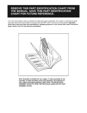
... small parts used in assembly. Note: Assembly is provided to the key number of this manual. The number in parenthesis below each stage is packaged separately. This chart is divided into four stages: 1) frame assembly, 2) arm assembly, 3) cable assembly, and 4) seat assembly. Important: Some parts may have been pre-assembled for each part refers to help you cannot find a part in the centre of the part from the PART LIST in the parts bags...
... small parts used in assembly. Note: Assembly is provided to the key number of this manual. The number in parenthesis below each stage is packaged separately. This chart is divided into four stages: 1) frame assembly, 2) arm assembly, 3) cable assembly, and 4) seat assembly. Important: Some parts may have been pre-assembled for each part refers to help you cannot find a part in the centre of the part from the PART LIST in the parts bags...


