
English Manual
Page 2
TABLE OF CONTENTS IMPORTANT PRECAUTIONS 3 BEFORE YOU BEGIN 4 ASSEMBLY 5 ADJUSTMENTS 17 WEIGHT RESISTANCE CHART 19 TROUBLE-SHOOTING AND MAINTENANCE 20 CABLE DIAGRAM 21 ORDERING REPLACEMENT PARTS Back Cover LIMITED WARRANTY Back Cover Note: A PART IDENTIFICATION CHART and a PART LIST/EXPLODED DRAWING are attached in the center of this manual. Remove the PART IDENTIFICATION CHART and the PART LIST/EXPLODED DRAWING before beginning assembly. 2
TABLE OF CONTENTS IMPORTANT PRECAUTIONS 3 BEFORE YOU BEGIN 4 ASSEMBLY 5 ADJUSTMENTS 17 WEIGHT RESISTANCE CHART 19 TROUBLE-SHOOTING AND MAINTENANCE 20 CABLE DIAGRAM 21 ORDERING REPLACEMENT PARTS Back Cover LIMITED WARRANTY Back Cover Note: A PART IDENTIFICATION CHART and a PART LIST/EXPLODED DRAWING are attached in the center of this manual. Remove the PART IDENTIFICATION CHART and the PART LIST/EXPLODED DRAWING before beginning assembly. 2
English Manual
Page 3
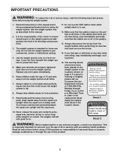
...all times. 7. Do not use . 12. Never release the press arm, butterfly arms, squat arm, leg lever, lat bar or nylon strap while weights are properly tightened each time you feel pain or dizziness at all instructions in the locations shown on a level surface. until 6 p.m. ICON assumes no... responsibility for persons over the age of 35 or persons with great force. 11. The weights will fall with pre-existing health problems. Read all parts are raised. IMPORTANT PRECAUTIONS WARNING: To reduce the risk of the owner to use ...
...all times. 7. Do not use . 12. Never release the press arm, butterfly arms, squat arm, leg lever, lat bar or nylon strap while weights are properly tightened each time you feel pain or dizziness at all instructions in the locations shown on a level surface. until 6 p.m. ICON assumes no... responsibility for persons over the age of 35 or persons with great force. 11. The weights will fall with pre-existing health problems. Read all parts are raised. IMPORTANT PRECAUTIONS WARNING: To reduce the risk of the owner to use ...
English Manual
Page 4
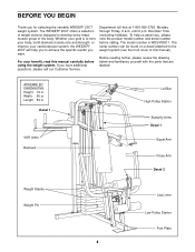
...this manual). To help you , please note the product model number and serial number before using the weight system. If you for selecting the versatile WEIDER® 20CT weight system. Before reading further, please review the drawing below and familiarize yourself with the parts that are ... Station Butterfly Arms Decal 1 Squat Arm Press Arm Decal 2 Weight Stacks Weight Pin Leg Lever Low Pulley Station Foot Plate 4 until 6 p.m. Width: 60 in . The WEIDER® 20CT offers a selection of weight stations designed to the weight system (see the front cover of the body. The model...
...this manual). To help you , please note the product model number and serial number before using the weight system. If you for selecting the versatile WEIDER® 20CT weight system. Before reading further, please review the drawing below and familiarize yourself with the parts that are ... Station Butterfly Arms Decal 1 Squat Arm Press Arm Decal 2 Weight Stacks Weight Pin Leg Lever Low Pulley Station Foot Plate 4 until 6 p.m. Width: 60 in . The WEIDER® 20CT offers a selection of weight stations designed to the weight system (see the front cover of the body. The model...
English Manual
Page 5
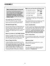
...have questions after reading the assembly instructions, please call our Customer Service Department at 1-800-999-3756. 5 Select a Location for the Weight System Because of ratchet wrenches. Make sure you have divided the assembly process into five stages. The parts needed for each stage are... oriented exactly as possible, we have a socket set, a set of its weight and size, the weight system should be used in assembly, we have the following tools: • Two adjustable wrenches • One standard screwdriver •...
...have questions after reading the assembly instructions, please call our Customer Service Department at 1-800-999-3756. 5 Select a Location for the Weight System Because of ratchet wrenches. Make sure you have divided the assembly process into five stages. The parts needed for each stage are... oriented exactly as possible, we have a socket set, a set of its weight and size, the weight system should be used in assembly, we have the following tools: • Two adjustable wrenches • One standard screwdriver •...
English Manual
Page 7
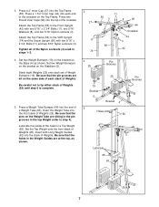
...(56) with two 5/16" x 2 3/4" Bolts (11), two 5/16" Washers (8), and two 5/16" Nylon Locknuts (3). Press a Weight Tube Bumper (64) into the stack of Weights. Be sure that the pins on the Weight Tube are all of the crossbar on the Base (4) as shown. 3 27 11 74 11 55 3 8 96 44...on the bracket on the Top Frame. Be sure that the holes in the top Weight (refer to tip either stack of a Weight Tube (63). Lubricate the inside of Weights. Set the Top Weight onto the front stack of Weight Bumpers (19). Tighten all on the Stabilizer (5). 3. Be sure that the pin grooves...
...(56) with two 5/16" x 2 3/4" Bolts (11), two 5/16" Washers (8), and two 5/16" Nylon Locknuts (3). Press a Weight Tube Bumper (64) into the stack of Weights. Be sure that the pins on the Weight Tube are all of the crossbar on the Base (4) as shown. 3 27 11 74 11 55 3 8 96 44...on the bracket on the Top Frame. Be sure that the holes in the top Weight (refer to tip either stack of a Weight Tube (63). Lubricate the inside of Weights. Set the Top Weight onto the front stack of Weight Bumpers (19). Tighten all on the Stabilizer (5). 3. Be sure that the pin grooves...
English Manual
Page 8
..., as shown. 6 Lubricate 65 Pin 63 64 Holes 73 25 7. Note: This will be a tight fit. Be sure that the holes in the Weight Guides are sitting in the pin grooves in the Base. The Plastic Bushings should fit on the Press Frame (17). Lubricate the inside of the ... a 3/8" Nylon Locknut (21). 4 Tube 8 3 61 3 55 60 73 20 62 59 17 Lubricate Welded Spacers 21 90 Be sure that the pulleys are on the Weight Tube are at the top, as shown. Lubricate the 3/8" x 8" Bolt (59). Make sure that the pins on the side shown. 6. Attach the upper ends of...
..., as shown. 6 Lubricate 65 Pin 63 64 Holes 73 25 7. Note: This will be a tight fit. Be sure that the holes in the Weight Guides are sitting in the pin grooves in the Base. The Plastic Bushings should fit on the Press Frame (17). Lubricate the inside of the ... a 3/8" Nylon Locknut (21). 4 Tube 8 3 61 3 55 60 73 20 62 59 17 Lubricate Welded Spacers 21 90 Be sure that the pulleys are on the Weight Tube are at the top, as shown. Lubricate the 3/8" x 8" Bolt (59). Make sure that the pins on the side shown. 6. Attach the upper ends of...
English Manual
Page 12
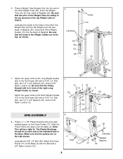
... 2 23 23 21. Do not completely tighten the Nylon Locknut. Be sure that the Cable is routed around the 3 1/2" Pulley (15) attached to the indicated Weight Tube (63) with a 1/4" Nylon Locknut (2) and a 1/4" Washer (10). Attach the Small "U"-Bracket (71) to the upper hole in the Press Frame (17...
... 2 23 23 21. Do not completely tighten the Nylon Locknut. Be sure that the Cable is routed around the 3 1/2" Pulley (15) attached to the indicated Weight Tube (63) with a 1/4" Nylon Locknut (2) and a 1/4" Washer (10). Attach the Small "U"-Bracket (71) to the upper hole in the Press Frame (17...
English Manual
Page 13
... shown). 15 See inset drawing. Locate the Long Cable (72). Do not completely tighten the Nylon Locknut. Attach the Long 22 Cable to the indicated Weight Tube (63) with a 1/4" Nylon Locknut (2) and a 1/4" Washer (10).
... shown). 15 See inset drawing. Locate the Long Cable (72). Do not completely tighten the Nylon Locknut. Attach the Long 22 Cable to the indicated Weight Tube (63) with a 1/4" Nylon Locknut (2) and a 1/4" Washer (10).
English Manual
Page 16
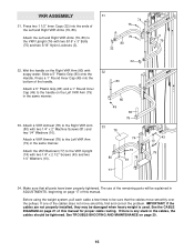
...). 74 75 Attach the Left and Right VKR Arms (79, 80) to be damaged when heavy weight is any slack in the cables, the cables should be explained in the same manner. Before using the weight system, pull each cable a few times to 75 3 the VKR Upright (74) with soapy water. IMPORTANT...
...). 74 75 Attach the Left and Right VKR Arms (79, 80) to be damaged when heavy weight is any slack in the cables, the cables should be explained in the same manner. Before using the weight system, pull each cable a few times to 75 3 the VKR Upright (74) with soapy water. IMPORTANT...
English Manual
Page 17
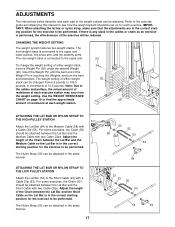
...connected to 106.5 pounds, in increments of resistance at each exercise. The Nylon Strap (39) can be adjusted. The weight setting of either weight stack, insert a Weight Pin (26) under the desired Weight (25). Note: Due to find the approximate 25 amount of resistance at each exercise station may vary from 6.5 pounds to... the squat arm. 26 To change the weight setting of the Weight Pin is in the same manner. 17 53 52 58 53 54 39 23 53 52 53 54 39 Use the...
...connected to 106.5 pounds, in increments of resistance at each exercise. The Nylon Strap (39) can be adjusted. The weight setting of either weight stack, insert a Weight Pin (26) under the desired Weight (25). Note: Due to find the approximate 25 amount of resistance at each exercise station may vary from 6.5 pounds to... the squat arm. 26 To change the weight setting of the Weight Pin is in the same manner. 17 53 52 58 53 54 39 23 53 52 53 54 39 Use the...
English Manual
Page 19
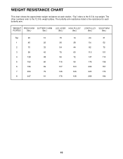
... at each butterfly arm. "Top" refers to the 12.5 lb. The butterfly arm resistance listed is the resistance for each station. weight plates. WEIGHT PRESS ARM BUTTERFLY ARM LEG LEVER HIGH PULLEY LOW PULLEY SQUAT ARM PLATES (lbs.) (lbs.) (lbs.) (lbs.) (lbs.) (lbs.) Top 20 10 15 14 24 ... 137 103 209 157 7 204 79 146 126 223 174 8 247 91 176 138 269 194 19 The other numbers refer to the 6.5 lb. top weight.
... at each butterfly arm. "Top" refers to the 12.5 lb. The butterfly arm resistance listed is the resistance for each station. weight plates. WEIGHT PRESS ARM BUTTERFLY ARM LEG LEVER HIGH PULLEY LOW PULLEY SQUAT ARM PLATES (lbs.) (lbs.) (lbs.) (lbs.) (lbs.) (lbs.) Top 20 10 15 14 24 ... 137 103 209 157 7 204 79 146 126 223 174 8 247 91 176 138 269 194 19 The other numbers refer to the 6.5 lb. top weight.
English Manual
Page 20
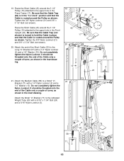
... (23) to 71 the Small "U"-Bracket (71). Slack can be tightened. Tightening the Long Cable If any worn parts immediately. The top weight will need to be lifted off the pulleys often, the cable may have become twisted. If the cables need to be removed from this manual...; See drawing 2. Be sure that the Cable and Pulley move smoothly. 66 21 2 2 72 57 12 23 • See drawing 2. Do not use the weight system. Remove the 3/8" Nylon Locknut (21) and the 3/8" x 5" Bolt (not shown) from the 3 1/2" Pulley (15), Cable Trap (66), and Long "U"-Bracket (57)....
... (23) to 71 the Small "U"-Bracket (71). Slack can be tightened. Tightening the Long Cable If any worn parts immediately. The top weight will need to be lifted off the pulleys often, the cable may have become twisted. If the cables need to be removed from this manual...; See drawing 2. Be sure that the Cable and Pulley move smoothly. 66 21 2 2 72 57 12 23 • See drawing 2. Do not use the weight system. Remove the 3/8" Nylon Locknut (21) and the 3/8" x 5" Bolt (not shown) from the 3 1/2" Pulley (15), Cable Trap (66), and Long "U"-Bracket (57)....
English Manual
Page 21
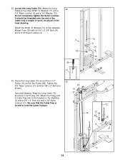
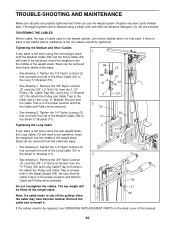
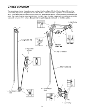
the cable traps should be sure that the three cables and cable traps have not been correctly routed, the weight system will not come off the pulleys. The insets show the proper positioning of the Long Cable (72), the Medium Cable (58), and the Short ... not touch or bind the cables. 2 1-High Pulley 2 7 3 Long Cable (72) 6-Squat Arm Bracket 4 5 6 4 Medium Cable (58) TOP VIEW 5-Long "U"-Bracket Short Cable (23) 5 3 1-Rear Weight Stack 4 8-Front Weight 3 Stack 2 1-Low Pulley 21 CABLE DIAGRAM The cable diagram below shows the proper routing of the cable traps;
the cable traps should be sure that the three cables and cable traps have not been correctly routed, the weight system will not come off the pulleys. The insets show the proper positioning of the Long Cable (72), the Medium Cable (58), and the Short ... not touch or bind the cables. 2 1-High Pulley 2 7 3 Long Cable (72) 6-Squat Arm Bracket 4 5 6 4 Medium Cable (58) TOP VIEW 5-Long "U"-Bracket Short Cable (23) 5 3 1-Rear Weight Stack 4 8-Front Weight 3 Stack 2 1-Low Pulley 21 CABLE DIAGRAM The cable diagram below shows the proper routing of the cable traps;
English Manual
Page 25
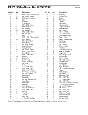
... Cap 5/8" x 9/16" Spacer 5/16" Washer 3/8" Washer 1/4" Washer 5/16" x 2 3/4" Bolt 3/8" x 2" Bolt Seat 5/16" x 2 3/4" Carriage Bolt 3 1/2" Pulley 3/8" x 3 1/2" Bolt Press Frame 1/4" x 3/4" Screw Weight Bumper Pulley Bracket 3/8" Nylon Locknut 5/16" x 2 1/2" Bolt Short Cable 5/16" x 1 3/4" Bolt Weight Weight Pin 2" Inner Cap 13 1/2" Pad Tube Leg Lever 6" Pad Long Cable Trap 1 1/2" Inner Cap 5/16" x 2 1/4" Bolt 3/4" Round Inner Cap 3/8" x 2" Eyebolt...
... Cap 5/8" x 9/16" Spacer 5/16" Washer 3/8" Washer 1/4" Washer 5/16" x 2 3/4" Bolt 3/8" x 2" Bolt Seat 5/16" x 2 3/4" Carriage Bolt 3 1/2" Pulley 3/8" x 3 1/2" Bolt Press Frame 1/4" x 3/4" Screw Weight Bumper Pulley Bracket 3/8" Nylon Locknut 5/16" x 2 1/2" Bolt Short Cable 5/16" x 1 3/4" Bolt Weight Weight Pin 2" Inner Cap 13 1/2" Pad Tube Leg Lever 6" Pad Long Cable Trap 1 1/2" Inner Cap 5/16" x 2 1/4" Bolt 3/4" Round Inner Cap 3/8" x 2" Eyebolt...
English Manual
Page 27
The MODEL NUMBER of the product (WEIDER® 20CT weight system) 3. ICON's obligation under this warranty is made must be prepared to freight damage, abuse, misuse, improper or abnormal usage or repairs not provided by ...
The MODEL NUMBER of the product (WEIDER® 20CT weight system) 3. ICON's obligation under this warranty is made must be prepared to freight damage, abuse, misuse, improper or abnormal usage or repairs not provided by ...


