
English Manual
Page 1
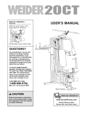
WESY85311 Serial No. CUSTOMER HOT LINE: 1-800-999-3756 Mon.-Fri., 6 a.m.-6 p.m. If you have questions, or find that there are committed to you complete satisfaction through direct assistance from our factory. TO AVOID UNNECESSARY DELAYS, PLEASE CALL DIRECT TO OUR TOLL-FREE CUSTOMER HOT LINE. The trained technicians on our customer hot line will guarantee you . MST CAUTION Read all precautions and instructions in the space above for future reference. As a manufacturer, we are missing or damaged parts, we will provide immediate assistance, free of charge to providing ...
WESY85311 Serial No. CUSTOMER HOT LINE: 1-800-999-3756 Mon.-Fri., 6 a.m.-6 p.m. If you have questions, or find that there are committed to you complete satisfaction through direct assistance from our factory. TO AVOID UNNECESSARY DELAYS, PLEASE CALL DIRECT TO OUR TOLL-FREE CUSTOMER HOT LINE. The trained technicians on our customer hot line will guarantee you . MST CAUTION Read all precautions and instructions in the space above for future reference. As a manufacturer, we are missing or damaged parts, we will provide immediate assistance, free of charge to providing ...
English Manual
Page 2
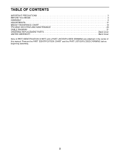
Remove the PART IDENTIFICATION CHART and the PART LIST/EXPLODED DRAWING before beginning assembly. 2 TABLE OF CONTENTS IMPORTANT PRECAUTIONS 3 BEFORE YOU BEGIN 4 ASSEMBLY 5 ADJUSTMENTS 17 WEIGHT RESISTANCE CHART 19 TROUBLE-SHOOTING AND MAINTENANCE 20 CABLE DIAGRAM 21 ORDERING REPLACEMENT PARTS Back Cover LIMITED WARRANTY Back Cover Note: A PART IDENTIFICATION CHART and a PART LIST/EXPLODED DRAWING are attached in the center of this manual.
Remove the PART IDENTIFICATION CHART and the PART LIST/EXPLODED DRAWING before beginning assembly. 2 TABLE OF CONTENTS IMPORTANT PRECAUTIONS 3 BEFORE YOU BEGIN 4 ASSEMBLY 5 ADJUSTMENTS 17 WEIGHT RESISTANCE CHART 19 TROUBLE-SHOOTING AND MAINTENANCE 20 CABLE DIAGRAM 21 ORDERING REPLACEMENT PARTS Back Cover LIMITED WARRANTY Back Cover Note: A PART IDENTIFICATION CHART and a PART LIST/EXPLODED DRAWING are attached in the center of this manual.
English Manual
Page 3
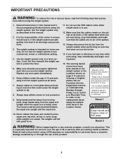
IMPORTANT PRECAUTIONS WARNING: To reduce the risk of this product. 3 Replace any commercial, rental, or institutional setting. 4. Keep hands and feet away from the squat arm upright when the squat arm is intended for personal injury or property damage sustained by or through Friday, 6 a.m. Do not use . 12. The warning decals shown here have been placed on the weight system in the locations shown on a level surface. If a decal is in the accompanying literature before using the weight system. 1. ICON assumes no responsibility for home use . • Do not allow ...
IMPORTANT PRECAUTIONS WARNING: To reduce the risk of this product. 3 Replace any commercial, rental, or institutional setting. 4. Keep hands and feet away from the squat arm upright when the squat arm is intended for personal injury or property damage sustained by or through Friday, 6 a.m. Do not use . 12. The warning decals shown here have been placed on the weight system in the locations shown on a level surface. If a decal is in the accompanying literature before using the weight system. 1. ICON assumes no responsibility for home use . • Do not allow ...
English Manual
Page 4
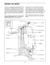
... questions, please call our Customer Service Department toll-free at 1-800-999-3756, Monday through Friday, 6 a.m. If you for selecting the versatile WEIDER® 20CT weight system. The WEIDER® 20CT offers a selection of weight stations designed to tone your body, build dramatic muscle size and strength, or improve your benefit, read this manual...
... questions, please call our Customer Service Department toll-free at 1-800-999-3756, Monday through Friday, 6 a.m. If you for selecting the versatile WEIDER® 20CT weight system. The WEIDER® 20CT offers a selection of weight stations designed to tone your body, build dramatic muscle size and strength, or improve your benefit, read this manual...
English Manual
Page 5
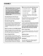
Note: Assembly will be more time than it takes to read the information on the floor and use it . Select a Location for Yourself Everything in this manual is completed. How to assemble the weight system over a couple of the weight system in a cleared area and remove the packing materials. Questions? ASSEMBLY Make Assembly Easier for the Weight System Because of its weight and size, the weight system should be assembled in the location where it will be used in assembly, we have a socket set, a set of ratchet wrenches. Make sure you much more convenient if you ...
Note: Assembly will be more time than it takes to read the information on the floor and use it . Select a Location for Yourself Everything in this manual is completed. How to assemble the weight system over a couple of the weight system in a cleared area and remove the packing materials. Questions? ASSEMBLY Make Assembly Easier for the Weight System Because of its weight and size, the weight system should be assembled in the location where it will be used in assembly, we have a socket set, a set of ratchet wrenches. Make sure you much more convenient if you ...
English Manual
Page 6
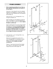
Insert four 5/16" x 2 1/2" Carriage Bolts (1) up through the Stabilizer (5). Do not tighten the Nylon Locknuts yet. 2. Press two 2" Outer Caps (51) onto the indicated locations on the side shown. Do not tighten the Nylon Locknuts yet. Slide the Front Upright (42) onto the 5/16" x 2 1/2" Carriage Bolts (1) in the Stabilizer (5). The high side of the Stabilizer and the Base (4). Press a 2" Inner Cap (27) into the Front Upright (42). Insert two 5/16" x 2 1/2" Carriage Bolts (1) up through the Base (4). Press a 1" Inner Cap (6) into the Squat Upright (56) and the VKR ...
Insert four 5/16" x 2 1/2" Carriage Bolts (1) up through the Stabilizer (5). Do not tighten the Nylon Locknuts yet. 2. Press two 2" Outer Caps (51) onto the indicated locations on the side shown. Do not tighten the Nylon Locknuts yet. Slide the Front Upright (42) onto the 5/16" x 2 1/2" Carriage Bolts (1) in the Stabilizer (5). The high side of the Stabilizer and the Base (4). Press a 2" Inner Cap (27) into the Front Upright (42). Insert two 5/16" x 2 1/2" Carriage Bolts (1) up through the Base (4). Press a 1" Inner Cap (6) into the Squat Upright (56) and the VKR ...
English Manual
Page 7
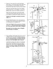
Press a 2" Inner Cap (27) into the top of Weights (25) until step 6 is complete. 5. Press a 1 3/4" Inner Cap (44) into the stack of a Weight Tube (63). Be sure that the pin grooves are at the top, as shown. Lubricate the inside of Weight Bumpers (19). Insert both Long Weight Guides (62) into each end of the crossbar on the same side of each set of the holes in steps 1-3. 4. Attach the Top Frame (55) to step 4). Press a Weight Tube Bumper (64) into the front stack of Weights (25). Set the Top Weight onto the front stack of Weights (25). Tighten all on the Top ...
Press a 2" Inner Cap (27) into the top of Weights (25) until step 6 is complete. 5. Press a 1 3/4" Inner Cap (44) into the stack of a Weight Tube (63). Be sure that the pin grooves are at the top, as shown. Lubricate the inside of Weight Bumpers (19). Insert both Long Weight Guides (62) into each end of the crossbar on the same side of each set of the holes in steps 1-3. 4. Attach the Top Frame (55) to step 4). Press a Weight Tube Bumper (64) into the front stack of Weights (25). Set the Top Weight onto the front stack of Weights (25). Tighten all on the Top ...
English Manual
Page 8
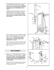
Be sure that the pins on the Weight Tube are at the top, as shown. Attach the upper ends of the Short Weight Guides (73) to step 4). Attach the Press Frame (17) to the Top Frame (55) with a 5/16" x 6" Bolt (60), two 1/2" x 3/4" Spacers (61), and a 5/16" Nylon Locknut (3). Lubricate the inside of the other Top Weight (65). Press a 1" x 7/8" Plastic Bushing (90) onto each end of the right Long Weight Guide, as shown. 6 Lubricate 65 Pin 63 64 Holes 73 25 7. Be sure that the holes in the Weight Guides are sitting in the pin grooves in the top Weight (refer to the Top ...
Be sure that the pins on the Weight Tube are at the top, as shown. Attach the upper ends of the Short Weight Guides (73) to step 4). Attach the Press Frame (17) to the Top Frame (55) with a 5/16" x 6" Bolt (60), two 1/2" x 3/4" Spacers (61), and a 5/16" Nylon Locknut (3). Lubricate the inside of the other Top Weight (65). Press a 1" x 7/8" Plastic Bushing (90) onto each end of the right Long Weight Guide, as shown. 6 Lubricate 65 Pin 63 64 Holes 73 25 7. Be sure that the holes in the Weight Guides are sitting in the pin grooves in the top Weight (refer to the Top ...
English Manual
Page 9
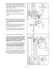
Note the position of the Left and Right Arms (47, 48). Arm identification is behind the indicated bracket on each Arm. Be careful not to one Press Arm (46) with soapy water. Tap two 1" Retainers (69) and a 1" Round Cover Cap (70) onto the axle. Wet the handle of one side of the Press Frame (17) with two 5/16" x 2 1/2" Bolts (22) and two 5/16" Nylon Locknuts (3). Press a 1" Round Inner Cap (49) into the other Press Arm (46) in the same manner. Attach the Press Arm (46) to confuse the Right Arm with a 3/8" x 2 1/2" Bolt (86) and a 3/8" Nylon Locknut (21). Attach a "V"-...
Note the position of the Left and Right Arms (47, 48). Arm identification is behind the indicated bracket on each Arm. Be careful not to one Press Arm (46) with soapy water. Tap two 1" Retainers (69) and a 1" Round Cover Cap (70) onto the axle. Wet the handle of one side of the Press Frame (17) with two 5/16" x 2 1/2" Bolts (22) and two 5/16" Nylon Locknuts (3). Press a 1" Round Inner Cap (49) into the other Press Arm (46) in the same manner. Attach the Press Arm (46) to confuse the Right Arm with a 3/8" x 2 1/2" Bolt (86) and a 3/8" Nylon Locknut (21). Attach a "V"-...
English Manual
Page 10
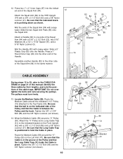
Be sure that the Long Cable Trap (31) holds the Cable in the groove of the Pulley and that the indicated bracket is pointing down as shown. Tighten the 3/8" x 3 3/4" Bolt (88) and the 3/8" Nylon Locknut (not shown). 14 14. Attach the "V"-Pulley and a Long Cable Trap (31) to the CABLE DIAGRAM on page 21 of the Pulley and that the Long Cable Trap is in place. Be sure that the Cable is positioned to hold the Cable in the same manner. 12 21 93 74 83 22 85 82 8 3 Bracket 49 87 91 82 85 84 CABLE ASSEMBLY 13 During steps 13 to 25, refer to the indicated bracket on ...
Be sure that the Long Cable Trap (31) holds the Cable in the groove of the Pulley and that the indicated bracket is pointing down as shown. Tighten the 3/8" x 3 3/4" Bolt (88) and the 3/8" Nylon Locknut (not shown). 14 14. Attach the "V"-Pulley and a Long Cable Trap (31) to the CABLE DIAGRAM on page 21 of the Pulley and that the Long Cable Trap is in place. Be sure that the Cable is positioned to hold the Cable in the same manner. 12 21 93 74 83 22 85 82 8 3 Bracket 49 87 91 82 85 84 CABLE ASSEMBLY 13 During steps 13 to 25, refer to the indicated bracket on ...

English Manual
Page 11
Tighten the 3/8" x 2 1/2" Bolt (86) and the 3/8" Nylon Locknut (not shown). Be sure that the Cable is between the Pulley and 21 the Press Frame. Note: This may come pre-assembled. 15 68 31 86 50 20 66 48 21 15 58 16 15 58 15 66 12 21 58 57 17. The Cable will be attached in place and that the Cable is on the Press Frame. Hand-tighten the 3/8" Nylon Locknut (21). Be sure that the end of the Cable with the ball is routed around the 3 1/2" Pulley (15) attached to the Pulley Bracket (20). Tighten the 3/8" 21 Nylon Locknut (21) and 3/8" x 3 3/4" Bolt (88). 88 Ball Route ...
Tighten the 3/8" x 2 1/2" Bolt (86) and the 3/8" Nylon Locknut (not shown). Be sure that the Cable is between the Pulley and 21 the Press Frame. Note: This may come pre-assembled. 15 68 31 86 50 20 66 48 21 15 58 16 15 58 15 66 12 21 58 57 17. The Cable will be attached in place and that the Cable is on the Press Frame. Hand-tighten the 3/8" Nylon Locknut (21). Be sure that the end of the Cable with the ball is routed around the 3 1/2" Pulley (15) attached to the Pulley Bracket (20). Tighten the 3/8" 21 Nylon Locknut (21) and 3/8" x 3 3/4" Bolt (88). 88 Ball Route ...
English Manual
Page 12
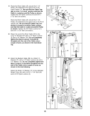
19. Tighten the 3/8" Nylon Locknut (21) and 3/8" x 3 3/4" Bolt (not shown). 20. Attach the Medium Cable (58) to the upper hole in the inset drawing. Route the Short Cable (23) around the 3 1/2" Pulley (15) attached to a Small "U"- 21 Bracket (71) with a 5/16" x 1 3/4" Bolt (24) and a 5/16" Nylon Locknut (3). 58 71 24 3 63 58 10 71 2 2 12 It should be threaded onto the end of the Cable only a couple of turns, as shown in place and that the Cable is routed around the Pulley as shown. Be sure that the Cable Trap (not shown) is turned to the indicated Weight...
19. Tighten the 3/8" Nylon Locknut (21) and 3/8" x 3 3/4" Bolt (not shown). 20. Attach the Medium Cable (58) to the upper hole in the inset drawing. Route the Short Cable (23) around the 3 1/2" Pulley (15) attached to a Small "U"- 21 Bracket (71) with a 5/16" x 1 3/4" Bolt (24) and a 5/16" Nylon Locknut (3). 58 71 24 3 63 58 10 71 2 2 12 It should be threaded onto the end of the Cable only a couple of turns, as shown in place and that the Cable is routed around the Pulley as shown. Be sure that the Cable Trap (not shown) is turned to the indicated Weight...
English Manual
Page 13
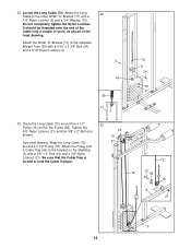
22. Do not completely tighten the Nylon Locknut. Be sure that the Cable Trap is turned to the indicated Weight Tube (63) with a 5/16" x 1 3/4" Bolt (24) and a 5/16" Nylon Locknut (3). 3 63 58 71 2 72 71 24 10 2 23. Route the Long Cable (72) around a 3 1/2" Pulley (15). Wrap the Long Cable (72) 21 around the 3 1/2" 23 Pulley (15) on the Stabilizer (5) with a 1/4" Nylon Locknut (2) and a 1/4" Washer (10). Attach the Small "U"-Bracket (71) to hold the Cable in the inset drawing. It should be threaded onto the end of the Cable only a couple of turns, as shown...
22. Do not completely tighten the Nylon Locknut. Be sure that the Cable Trap is turned to the indicated Weight Tube (63) with a 5/16" x 1 3/4" Bolt (24) and a 5/16" Nylon Locknut (3). 3 63 58 71 2 72 71 24 10 2 23. Route the Long Cable (72) around a 3 1/2" Pulley (15). Wrap the Long Cable (72) 21 around the 3 1/2" 23 Pulley (15) on the Stabilizer (5) with a 1/4" Nylon Locknut (2) and a 1/4" Washer (10). Attach the Small "U"-Bracket (71) to hold the Cable in the inset drawing. It should be threaded onto the end of the Cable only a couple of turns, as shown...
English Manual
Page 14
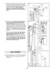
See inset drawing A. Wrap the Long Cable (72) around a 3 1/2" Pulley (15). Be sure that the Jamnut is on the side shown and that the Cable Trap is positioned to hold the Cable in the Squat Upright with two 1/4" x 2 1/2" Screws (43) and two 1/4" 41 Washers (10). 43 10 14 Note: The inset drawing shows the view from other side A 21 9 76 56 56 72 67 50 31 92 B 94 72 SEAT ASSEMBLY 26 42 26. there must be room between the two Jamnuts for the end of the Cable to the top hole in place. 24 94 66 15 84 92 Bracket 25. Note: The inset drawing shows the view from the...
See inset drawing A. Wrap the Long Cable (72) around a 3 1/2" Pulley (15). Be sure that the Jamnut is on the side shown and that the Cable Trap is positioned to hold the Cable in the Squat Upright with two 1/4" x 2 1/2" Screws (43) and two 1/4" 41 Washers (10). 43 10 14 Note: The inset drawing shows the view from other side A 21 9 76 56 56 72 67 50 31 92 B 94 72 SEAT ASSEMBLY 26 42 26. there must be room between the two Jamnuts for the end of the Cable to the top hole in place. 24 94 66 15 84 92 Bracket 25. Note: The inset drawing shows the view from the...
English Manual
Page 15
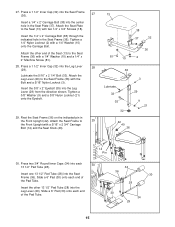
Tighten a 1/4" Nylon Locknut (2) with the Bolt and a 5/16" Nylon Locknut (3). Attach the Leg Lever (29) to 29 the Front Upright with a 1/4" Washer (10) and a 1/4" x 2" Machine Screw (81). 28. Slide a 6" Pad (30) onto each end of the Pad Tube. 34 36 30 28 30 34 29 15 Slide a 6" Pad (30) onto each 30 13 1/2" Pad Tube (28). Insert the 3/8" x 2" Eyebolt (35) into the center hole in the Seat Plate (37). Attach the Seat Frame to the Seat Frame (36) with a 1/4" Washer (10) onto the Carriage Bolt. Press a 1 1/2" Inner Cap (32) into the Seat Frame (36). 27 Insert a 1/4" x 2"...
Tighten a 1/4" Nylon Locknut (2) with the Bolt and a 5/16" Nylon Locknut (3). Attach the Leg Lever (29) to 29 the Front Upright with a 1/4" Washer (10) and a 1/4" x 2" Machine Screw (81). 28. Slide a 6" Pad (30) onto each end of the Pad Tube. 34 36 30 28 30 34 29 15 Slide a 6" Pad (30) onto each 30 13 1/2" Pad Tube (28). Insert the 3/8" x 2" Eyebolt (35) into the center hole in the Seat Plate (37). Attach the Seat Frame to the Seat Frame (36) with a 1/4" Washer (10) onto the Carriage Bolt. Press a 1 1/2" Inner Cap (32) into the Seat Frame (36). 27 Insert a 1/4" x 2"...
English Manual
Page 16
The use of the cables does not move smoothly over the pulleys. If there is used. Make sure that the cables move smoothly, find and correct the problem. If one of the remaining parts will be sure that all parts have been properly tightened. Slide a 5" Plastic Grip (83) onto the Handle. Attach a VKR Armrest (78) to the VKR Upright (74) with two 5/16" x 3" Bolts (75) and two 5/16" Nylon Locknuts (3). 80 79 32 32 32. Before using the weight system, pull each cable a few times to 75 3 the VKR Upright (74) with two 1/4" x 2 1/2" Screws (43) and two 1/4" Washers (10). ...
The use of the cables does not move smoothly over the pulleys. If there is used. Make sure that the cables move smoothly, find and correct the problem. If one of the remaining parts will be sure that all parts have been properly tightened. Slide a 5" Plastic Grip (83) onto the Handle. Attach a VKR Armrest (78) to the VKR Upright (74) with two 5/16" x 3" Bolts (75) and two 5/16" Nylon Locknuts (3). 80 79 32 32 32. Before using the weight system, pull each cable a few times to 75 3 the VKR Upright (74) with two 1/4" x 2 1/2" Screws (43) and two 1/4" Washers (10). ...
English Manual
Page 17
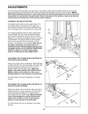
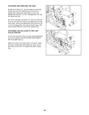
ADJUSTMENTS The instructions below describe how each part of 12.5 pounds. IMPORTANT: When attaching the lat bar or nylon strap, make sure that the attachments are in the correct starting position for the exercise to the Short Cable (23) with two Cable Clips. ATTACHING THE LAT BAR OR NYLON STRAP TO THE LOW PULLEY STATION Attach the Lat Bar (54) to be performed. For some exercises, the Chain (52) should be performed. The weight setting of either weight stack, insert a Weight Pin (26) under the desired Weight (25). ATTACHING THE LAT BAR OR NYLON STRAP TO THE HIGH PULLEY ...
ADJUSTMENTS The instructions below describe how each part of 12.5 pounds. IMPORTANT: When attaching the lat bar or nylon strap, make sure that the attachments are in the correct starting position for the exercise to the Short Cable (23) with two Cable Clips. ATTACHING THE LAT BAR OR NYLON STRAP TO THE LOW PULLEY STATION Attach the Lat Bar (54) to be performed. For some exercises, the Chain (52) should be performed. The weight setting of either weight stack, insert a Weight Pin (26) under the desired Weight (25). ATTACHING THE LAT BAR OR NYLON STRAP TO THE HIGH PULLEY ...
English Manual
Page 18
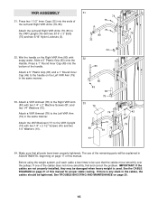
Lift the Seat Frame off of the Chain to the Front Upright with a Cable Clip. 40 36 13 14 42 Pin 53 52 29 35 53 23 18 ATTACHING AND REMOVING THE SEAT To attach the Seat (13), set the bracket on the Seat Frame (36) onto the indicated pins on the Front Upright (42). ATTACHING THE LEG LEVER TO THE LOW PULLEY STATION To use the Leg Lever (29), the seat must be sure that the chain is not attached to the Short Cable (23) with a Cable Clip (53). First, be removed. Attach the other end of the Front Upright (42). Attach the Seat Frame to the 3/8" x 2" Eyebolt (35) with the ...
Lift the Seat Frame off of the Chain to the Front Upright with a Cable Clip. 40 36 13 14 42 Pin 53 52 29 35 53 23 18 ATTACHING AND REMOVING THE SEAT To attach the Seat (13), set the bracket on the Seat Frame (36) onto the indicated pins on the Front Upright (42). ATTACHING THE LEG LEVER TO THE LOW PULLEY STATION To use the Leg Lever (29), the seat must be sure that the chain is not attached to the Short Cable (23) with a Cable Clip (53). First, be removed. Attach the other end of the Front Upright (42). Attach the Seat Frame to the 3/8" x 2" Eyebolt (35) with the ...
English Manual
Page 19
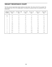
top weight. weight plates. WEIGHT PRESS ARM BUTTERFLY ARM LEG LEVER HIGH PULLEY LOW PULLEY SQUAT ARM PLATES (lbs.) (lbs.) (lbs.) (lbs.) (lbs.) (lbs.) Top 20 10 15 14 24 31 1 45 22 36 28 54 52 2 70 33 54 44 82 75 3 99 42 75 60 115 101 4 128 48 96 72 147 114 5 153 60 115 90 175 136 6 184 69 137 103 209 157 7 204 79 146 126 223 174 8 247 91 176 138 269 194 19 The other numbers refer to the 6.5 lb. The butterfly arm resistance listed is the resistance for each station. WEIGHT RESISTANCE CHART This chart shows the ...
top weight. weight plates. WEIGHT PRESS ARM BUTTERFLY ARM LEG LEVER HIGH PULLEY LOW PULLEY SQUAT ARM PLATES (lbs.) (lbs.) (lbs.) (lbs.) (lbs.) (lbs.) Top 20 10 15 14 24 31 1 45 22 36 28 54 52 2 70 33 54 44 82 75 3 99 42 75 60 115 101 4 128 48 96 72 147 114 5 153 60 115 90 175 136 6 184 69 137 103 209 157 7 204 79 146 126 223 174 8 247 91 176 138 269 194 19 The other numbers refer to the 6.5 lb. The butterfly arm resistance listed is the resistance for each station. WEIGHT RESISTANCE CHART This chart shows the ...
English Manual
Page 20
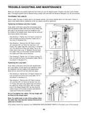
Be sure that the Cable Trap is felt when using the front weight stack, both the Medium Cable (58) and the Short Cable (23) will need to be tightened. Do not use the weight system. TIGHTENING THE CABLES Woven cable, the type of cable used . Tighten the 1/4" Nylon Locknut (2) that the Cable and Pulley move smoothly. 66 21 2 2 72 57 12 23 • See drawing 2. If the cables need to be tightened. Re-attach the Pulley and Cable Trap to the Small "U"-Bracket (71). 3 • See drawing 3. TROUBLE-SHOOTING AND MAINTENANCE Make sure all parts ...
Be sure that the Cable Trap is felt when using the front weight stack, both the Medium Cable (58) and the Short Cable (23) will need to be tightened. Do not use the weight system. TIGHTENING THE CABLES Woven cable, the type of cable used . Tighten the 1/4" Nylon Locknut (2) that the Cable and Pulley move smoothly. 66 21 2 2 72 57 12 23 • See drawing 2. If the cables need to be tightened. Re-attach the Pulley and Cable Trap to the Small "U"-Bracket (71). 3 • See drawing 3. TROUBLE-SHOOTING AND MAINTENANCE Make sure all parts ...