
English Manual
Page 1
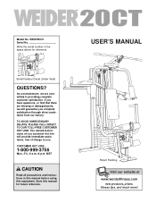
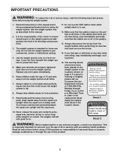
....com new products, prizes, fitness tips, and much more! WESY85311 Serial No. If you have questions, or find that there are committed to you complete satisfaction through direct assistance from our factory. MST CAUTION Read all precautions and instructions in the space above for future reference. Model No. Write the serial number in this manual before using this manual for reference.
....com new products, prizes, fitness tips, and much more! WESY85311 Serial No. If you have questions, or find that there are committed to you complete satisfaction through direct assistance from our factory. MST CAUTION Read all precautions and instructions in the space above for future reference. Model No. Write the serial number in this manual before using this manual for reference.
English Manual
Page 2
TABLE OF CONTENTS IMPORTANT PRECAUTIONS 3 BEFORE YOU BEGIN 4 ASSEMBLY 5 ADJUSTMENTS 17 WEIGHT RESISTANCE CHART 19 TROUBLE-SHOOTING AND MAINTENANCE 20 CABLE DIAGRAM 21 ORDERING REPLACEMENT PARTS Back Cover LIMITED WARRANTY Back Cover Note: A PART IDENTIFICATION CHART and a PART LIST/EXPLODED DRAWING are attached in the center of this manual. Remove the PART IDENTIFICATION CHART and the PART LIST/EXPLODED DRAWING before beginning assembly. 2
TABLE OF CONTENTS IMPORTANT PRECAUTIONS 3 BEFORE YOU BEGIN 4 ASSEMBLY 5 ADJUSTMENTS 17 WEIGHT RESISTANCE CHART 19 TROUBLE-SHOOTING AND MAINTENANCE 20 CABLE DIAGRAM 21 ORDERING REPLACEMENT PARTS Back Cover LIMITED WARRANTY Back Cover Note: A PART IDENTIFICATION CHART and a PART LIST/EXPLODED DRAWING are attached in the center of this manual. Remove the PART IDENTIFICATION CHART and the PART LIST/EXPLODED DRAWING before beginning assembly. 2
English Manual
Page 3
... arms, squat arm, leg lever, lat bar or nylon strap while weights are adequately informed of this product. 3 Decal 1 Keep hands and fingers clear of all times. ICON assumes no responsibility for persons over the age of the pulleys. 13. Make sure all of 35 or persons with great force. 11. Read all instructions in use only. Replace any commercial, rental, or institutional setting...
... arms, squat arm, leg lever, lat bar or nylon strap while weights are adequately informed of this product. 3 Decal 1 Keep hands and fingers clear of all times. ICON assumes no responsibility for persons over the age of the pulleys. 13. Make sure all of 35 or persons with great force. 11. Read all instructions in use only. Replace any commercial, rental, or institutional setting...
English Manual
Page 4
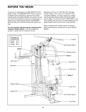
... this manual). Decal 1 VKR Arms Backrest Lat Bar High Pulley Station Butterfly Arms Decal 1 Squat Arm Press Arm Decal 2 Weight Stacks Weight Pin Leg Lever Low Pulley Station Foot Plate 4 If you , please note the product model number and serial number before using the weight system. until 6 p.m. The serial number can be found on a decal attached to develop every major muscle group of this manual carefully before calling. The model number is to achieve the specific results...
... this manual). Decal 1 VKR Arms Backrest Lat Bar High Pulley Station Butterfly Arms Decal 1 Squat Arm Press Arm Decal 2 Weight Stacks Weight Pin Leg Lever Low Pulley Station Foot Plate 4 If you , please note the product model number and serial number before using the weight system. until 6 p.m. The serial number can be found on a decal attached to develop every major muscle group of this manual carefully before calling. The model number is to achieve the specific results...
English Manual
Page 5
... reading the assembly instructions, please call our Customer Service Department at 1-800-999-3756. 5 Set Aside Enough Time How to Identify Parts Due to the many features of time and by anyone. Make sure that there is enough room to walk around the weight system as possible, we have been pre-attached. The parts needed for each stage to open -end...
... reading the assembly instructions, please call our Customer Service Department at 1-800-999-3756. 5 Set Aside Enough Time How to Identify Parts Due to the many features of time and by anyone. Make sure that there is enough room to walk around the weight system as possible, we have been pre-attached. The parts needed for each stage to open -end...
English Manual
Page 7
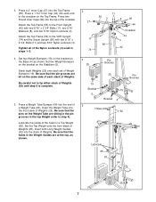
... of the Nylon Locknuts (3) used in the Weight Guides are sitting in the pin grooves in a Top Weight (65). Press a 2" Inner Cap (27) into the end of Weight Bumpers (19). Attach the Top Frame (55) to step 4). Tighten all on the Weight Tube are at the top, as shown. Press a Weight Tube Bumper (64) into the Top Frame (55). Set two Weight Bumpers (19) on...
... of the Nylon Locknuts (3) used in the Weight Guides are sitting in the pin grooves in a Top Weight (65). Press a 2" Inner Cap (27) into the end of Weight Bumpers (19). Attach the Top Frame (55) to step 4). Tighten all on the Weight Tube are at the top, as shown. Press a Weight Tube Bumper (64) into the Top Frame (55). Set two Weight Bumpers (19) on...
English Manual
Page 8
... Locknut (3). Set the Top Weight onto the rear stack of Weights (25). Be sure that the Pulley Bracket (20) is in the other Weight Tube (63). Lubricate the 3/8" x 8" Bolt (59). Insert both Short Weight Guides (73) into the rear stack of Weights (25). Press a 1" x 7/8" Plastic Bushing (90) onto each end of Weights. The Plastic Bushings should fit on the Weight Tube are sitting in the pin grooves...
... Locknut (3). Set the Top Weight onto the rear stack of Weights (25). Be sure that the Pulley Bracket (20) is in the other Weight Tube (63). Lubricate the 3/8" x 8" Bolt (59). Insert both Short Weight Guides (73) into the rear stack of Weights (25). Press a 1" x 7/8" Plastic Bushing (90) onto each end of Weights. The Plastic Bushings should fit on the Weight Tube are sitting in the pin grooves...
English Manual
Page 9
... the Right Arm (48) and the Left Arm (47). Attach a "V"-Pulley (50) and a Long Cable Trap (31) to the Left Arm (47) in the same manner. Note the position of the Right Arm is very important for step 11. Arm identification is behind the indicated bracket on each Arm. Slide a 10" Pad (45) onto the lower end of the Press Frame (17...
... the Right Arm (48) and the Left Arm (47). Attach a "V"-Pulley (50) and a Long Cable Trap (31) to the Left Arm (47) in the same manner. Note the position of the Right Arm is very important for step 11. Arm identification is behind the indicated bracket on each Arm. Slide a 10" Pad (45) onto the lower end of the Press Frame (17...
English Manual
Page 10
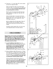
... that the Cable is positioned to the VKR Upright (74) with a 5/16" x 2 1/2" Bolt (22), two 5/16" Washers (8), a 1/2" x 17/32" Spacer (91), and a 5/16" Nylon Locknut (3). Route the Medium Cable around a "V"-Pulley (50). Wrap the Medium Cable (58) around the indicated 3 1/2" Pulley (15) attached to the other end of this manual. Attach the Squat Arm (84) to hold the Cable in place. Attach a Handle (82...
... that the Cable is positioned to the VKR Upright (74) with a 5/16" x 2 1/2" Bolt (22), two 5/16" Washers (8), a 1/2" x 17/32" Spacer (91), and a 5/16" Nylon Locknut (3). Route the Medium Cable around a "V"-Pulley (50). Wrap the Medium Cable (58) around the indicated 3 1/2" Pulley (15) attached to the other end of this manual. Attach the Squat Arm (84) to hold the Cable in place. Attach a Handle (82...

English Manual
Page 11
... Cable is routed around the 3 1/2" Pulley (15) attached to the lower hole in step 21. 57 Bracket 15 12 58 18. Be sure that the end of the Press Frame (17) and 15 23 9 that the Cable and Pulley move smoothly. Tighten the 3/8" Nylon Locknut (21) and 3/8" x 3 3/4" Bolt (not shown). 11 7 95 Crossbar 21 17 Route the Medium Cable (58) around the Pulley as shown. Route...
... Cable is routed around the 3 1/2" Pulley (15) attached to the lower hole in step 21. 57 Bracket 15 12 58 18. Be sure that the end of the Press Frame (17) and 15 23 9 that the Cable and Pulley move smoothly. Tighten the 3/8" Nylon Locknut (21) and 3/8" x 3 3/4" Bolt (not shown). 11 7 95 Crossbar 21 17 Route the Medium Cable (58) around the Pulley as shown. Route...
English Manual
Page 14
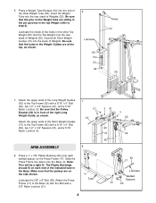
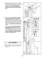
... 24 94 66 15 84 92 Bracket 25. Do not tighten the second Jamnut; Attach the Backrest (41) to the Squat Arm (84) with two 1/4" x 2 1/2" Screws (43) and two 1/4" 41 Washers (10). 43 10 14 Attach the Pulley and a Cable Trap (66) to the Front Upright (42) with the 3/8" x 2 1/4" Bolt (94) and a 3/8" Jamnut (92). Note: The inset...Position the Long Cable Trap as shown. Be sure that the Jamnut is on the side shown and that the Cable Trap is positioned to pivot. 25 50 72 72 Insets show view from the other side A 21 9 76 56 56 72 67 50 31 92 B 94 72 SEAT ASSEMBLY 26 42 ...
... 24 94 66 15 84 92 Bracket 25. Do not tighten the second Jamnut; Attach the Backrest (41) to the Squat Arm (84) with two 1/4" x 2 1/2" Screws (43) and two 1/4" 41 Washers (10). 43 10 14 Attach the Pulley and a Cable Trap (66) to the Front Upright (42) with the 3/8" x 2 1/4" Bolt (94) and a 3/8" Jamnut (92). Note: The inset...Position the Long Cable Trap as shown. Be sure that the Jamnut is on the side shown and that the Cable Trap is positioned to pivot. 25 50 72 72 Insets show view from the other side A 21 9 76 56 56 72 67 50 31 92 B 94 72 SEAT ASSEMBLY 26 42 ...
English Manual
Page 15
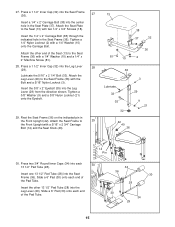
... (29) from the direction shown. Attach the Leg Lever (29) to the Seat Frame (36) with two 1/4" x 3/4" Screws (18). Press a 1 1/2" Inner Cap (32) into the center hole in the Seat Plate (37). Attach the Seat Frame to the Seat (13) with a 1/4" Washer (10) and a 1/4" x 2" Machine Screw (81). 28. Attach the Seat Plate to 29 the Front Upright with a 1/4" Washer (10) onto the Carriage Bolt. Tighten a 1/4" Nylon Locknut...
... (29) from the direction shown. Attach the Leg Lever (29) to the Seat Frame (36) with two 1/4" x 3/4" Screws (18). Press a 1 1/2" Inner Cap (32) into the center hole in the Seat Plate (37). Attach the Seat Frame to the Seat (13) with a 1/4" Washer (10) and a 1/4" x 2" Machine Screw (81). 28. Attach the Seat Plate to 29 the Front Upright with a 1/4" Washer (10) onto the Carriage Bolt. Tighten a 1/4" Nylon Locknut...
English Manual
Page 16
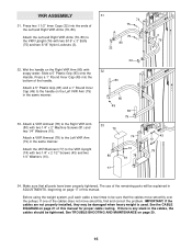
... one of this manual. IMPORTANT: If the cables are not properly installed, they may be sure that all parts have been properly tightened. Wet the handle on page 17 of the handle. Attach a VKR Armrest (78) to the handle on the Left VKR Arm (79) in ADJUSTMENTS, beginning on the Right VKR Arm (80) with two 1/4" x 2" Machine Screws (81) and two...
... one of this manual. IMPORTANT: If the cables are not properly installed, they may be sure that all parts have been properly tightened. Wet the handle on page 17 of the handle. Attach a VKR Armrest (78) to the handle on the Left VKR Arm (79) in ADJUSTMENTS, beginning on the Right VKR Arm (80) with two 1/4" x 2" Machine Screws (81) and two...
English Manual
Page 17
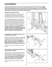
... set up for the exercise to the cables and pulleys, the actual amount of resistance at each weight station. The front weight stack is connected to the upper and lower pulleys, the press arm, and the butterfly arms. The rear weight stack is connected to be performed. The Nylon Strap (39) can be adjusted. ADJUSTMENTS The instructions below describe how each part of the weight system can be attached in the same manner. Use...
... set up for the exercise to the cables and pulleys, the actual amount of resistance at each weight station. The front weight stack is connected to the upper and lower pulleys, the press arm, and the butterfly arms. The rear weight stack is connected to be performed. The Nylon Strap (39) can be adjusted. ADJUSTMENTS The instructions below describe how each part of the weight system can be attached in the same manner. Use...
English Manual
Page 18
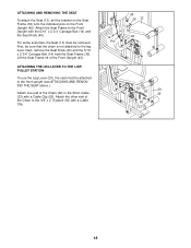
... 5/16" x 2 3/4" Carriage Bolt (14) and the Seat Knob (40). Attach the Seat Frame to the Short Cable (23) with a Cable Clip (53). ATTACHING AND REMOVING THE SEAT To attach the Seat (13), set the bracket on the Seat Frame (36) onto the indicated pins on the Front Upright (42). ATTACHING THE LEG LEVER TO THE LOW PULLEY STATION To use the Leg Lever (29), the seat must be attached to the leg lever. Lift...
... 5/16" x 2 3/4" Carriage Bolt (14) and the Seat Knob (40). Attach the Seat Frame to the Short Cable (23) with a Cable Clip (53). ATTACHING AND REMOVING THE SEAT To attach the Seat (13), set the bracket on the Seat Frame (36) onto the indicated pins on the Front Upright (42). ATTACHING THE LEG LEVER TO THE LOW PULLEY STATION To use the Leg Lever (29), the seat must be attached to the leg lever. Lift...
English Manual
Page 19
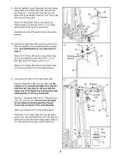
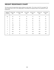
WEIGHT PRESS ARM BUTTERFLY ARM LEG LEVER HIGH PULLEY LOW PULLEY SQUAT ARM PLATES (lbs.) (lbs.) (lbs.) (lbs.) (lbs.) (lbs.) Top 20 10 15 14 24 31 1 45 22 36 28 54 52 2 70 33 54 44 82 ... 6 184 69 137 103 209 157 7 204 79 146 126 223 174 8 247 91 176 138 269 194 19 "Top" refers to the 12.5 lb. weight plates. The butterfly arm resistance listed is the resistance for each station. WEIGHT RESISTANCE CHART This chart shows the approximate weight resistance at each butterfly arm. top weight. The other numbers refer to the 6.5 lb.
WEIGHT PRESS ARM BUTTERFLY ARM LEG LEVER HIGH PULLEY LOW PULLEY SQUAT ARM PLATES (lbs.) (lbs.) (lbs.) (lbs.) (lbs.) (lbs.) Top 20 10 15 14 24 31 1 45 22 36 28 54 52 2 70 33 54 44 82 ... 6 184 69 137 103 209 157 7 204 79 146 126 223 174 8 247 91 176 138 269 194 19 "Top" refers to the 12.5 lb. weight plates. The butterfly arm resistance listed is the resistance for each station. WEIGHT RESISTANCE CHART This chart shows the approximate weight resistance at each butterfly arm. top weight. The other numbers refer to the 6.5 lb.
English Manual
Page 20
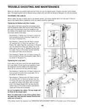
...-install it is felt when using a damp cloth and mild non-abrasive detergent. Tightening the Long Cable If any worn parts immediately. If there is slack in the cables before resistance is in the proper position and that the Cable and Pulley move smoothly. 56 Do not overtighten the cables. Remove the 3/8" Nylon Locknut (21) and the 3/8" x 2" Bolt (12) from this manual. 20 Re-attach...
...-install it is felt when using a damp cloth and mild non-abrasive detergent. Tightening the Long Cable If any worn parts immediately. If there is slack in the cables before resistance is in the proper position and that the Cable and Pulley move smoothly. 56 Do not overtighten the cables. Remove the 3/8" Nylon Locknut (21) and the 3/8" x 2" Bolt (12) from this manual. 20 Re-attach...
English Manual
Page 21
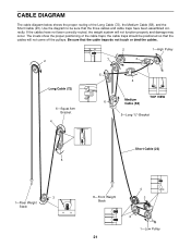
... touch or bind the cables. 2 1-High Pulley 2 7 3 Long Cable (72) 6-Squat Arm Bracket 4 5 6 4 Medium Cable (58) TOP VIEW 5-Long "U"-Bracket Short Cable (23) 5 3 1-Rear Weight Stack 4 8-Front Weight 3 Stack 2 1-Low Pulley 21 The insets show the proper positioning of the Long Cable (72), the Medium Cable (58), and the Short Cable (23). CABLE DIAGRAM The cable diagram below shows the proper routing of the cable traps; Be sure that...
... touch or bind the cables. 2 1-High Pulley 2 7 3 Long Cable (72) 6-Squat Arm Bracket 4 5 6 4 Medium Cable (58) TOP VIEW 5-Long "U"-Bracket Short Cable (23) 5 3 1-Rear Weight Stack 4 8-Front Weight 3 Stack 2 1-Low Pulley 21 The insets show the proper positioning of the Long Cable (72), the Medium Cable (58), and the Short Cable (23). CABLE DIAGRAM The cable diagram below shows the proper routing of the cable traps; Be sure that...
English Manual
Page 25
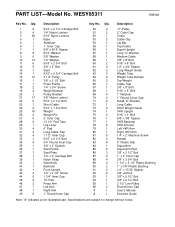
...3/8" x 5" Bolt 5/16" x 5" Bolt 1" Retainer 1" Round Cover Cap Small "U"-Bracket Long Cable Short Weight Guide VKR Upright 5/16" x 3" Bolt 5/8" x 3/8" Spacer VKR Backrest VKR Armrest Left VKR Arm Right VKR Arm 1/4" x 2" Machine Screw Handle 5" Plastic Grip Squat Arm Squat Arm Pad 3/8" x 2 1/2" Bolt 1" x 2" Inner Cap 3/8" x 3 3/4" Bolt 1 1/4" x 2 1/2" Plastic Bushing 1" x 7/8" Plastic Bushing 1/2" x 17/32" Spacer 3/8" Jamnut 3/8" x 5 1/2" Bolt 3/8" x 2 1/4" Bolt 3 1/2" Low Pulley Round Inner Cap User's Manual Exercise Guide Note: "#" indicates a non-illustrated part. WESY85311 R0802A Key No.
...3/8" x 5" Bolt 5/16" x 5" Bolt 1" Retainer 1" Round Cover Cap Small "U"-Bracket Long Cable Short Weight Guide VKR Upright 5/16" x 3" Bolt 5/8" x 3/8" Spacer VKR Backrest VKR Armrest Left VKR Arm Right VKR Arm 1/4" x 2" Machine Screw Handle 5" Plastic Grip Squat Arm Squat Arm Pad 3/8" x 2 1/2" Bolt 1" x 2" Inner Cap 3/8" x 3 3/4" Bolt 1 1/4" x 2 1/2" Plastic Bushing 1" x 7/8" Plastic Bushing 1/2" x 17/32" Spacer 3/8" Jamnut 3/8" x 5 1/2" Bolt 3/8" x 2 1/4" Bolt 3 1/2" Low Pulley Round Inner Cap User's Manual Exercise Guide Note: "#" indicates a non-illustrated part. WESY85311 R0802A Key No.
English Manual
Page 27
... consequential damages of purchase. until 6 p.m. The MODEL NUMBER of the product (WEIDER® 20CT weight system) 3. Some states do not allow the exclusion or limitation of this warranty is limited to replacing or repairing, at ICON's option, the product at 1-800-999-3756, Monday through Friday, 6 a.m. The KEY NUMBER and DESCRIPTION of the part(s) (see the front cover of incidental or consequential damages. The NAME...
... consequential damages of purchase. until 6 p.m. The MODEL NUMBER of the product (WEIDER® 20CT weight system) 3. Some states do not allow the exclusion or limitation of this warranty is limited to replacing or repairing, at ICON's option, the product at 1-800-999-3756, Monday through Friday, 6 a.m. The KEY NUMBER and DESCRIPTION of the part(s) (see the front cover of incidental or consequential damages. The NAME...


