
English Manual
Page 9
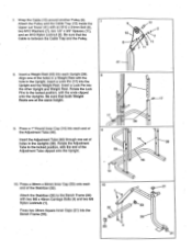
...8 42 . ° . . 17 ., 39 , . . . ..o.--17 . Insert a Lock Pin into the Bench Frame (33). 10 ........._ 1r IP 7 32 :" : . , 53 4 • gr___..--21 o 53 33 21 Press a 1" Round Inner Cap (14) into each end of holes in the Upright. Insert the Adjustment Tube (46) through ...Spacers (11), and an M10 Nylon Locknut (2). Insert a Lock Pin (17) into each end of the Adjustment Tube clipped onto the Upright. 39 e e 14 ,,, .-- Press a 38mm x 50mm Inner Cap (53) onto each Upright (39). Be sure that the Cable is between the Cable Trap and the Pulley. 9 10 8 0 12 ...
...8 42 . ° . . 17 ., 39 , . . . ..o.--17 . Insert a Lock Pin into the Bench Frame (33). 10 ........._ 1r IP 7 32 :" : . , 53 4 • gr___..--21 o 53 33 21 Press a 1" Round Inner Cap (14) into each end of holes in the Upright. Insert the Adjustment Tube (46) through ...Spacers (11), and an M10 Nylon Locknut (2). Insert a Lock Pin (17) into each end of the Adjustment Tube clipped onto the Upright. 39 e e 14 ,,, .-- Press a 38mm x 50mm Inner Cap (53) onto each Upright (39). Be sure that the Cable is between the Cable Trap and the Pulley. 9 10 8 0 12 ...


