
English Manual
Page 1
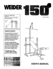
...; Serial Number Decal (Under Cross Brace) QUESTIONS? As a manufacturer, we are missing or damaged parts, we will provide immediate assistance, free of charge to providing complete customer satisfaction. TO AVOID UNNECESSARY DELAYS, PLEASE CALL DIRECT TO OUR TOLL-FREE CUSTOMER...space above for Aittireietereh6e. WEBE15061 Serial No. If you have questions, or find that there are committed to you complete satisfaction through direct assistance from our factory. The trained technicians on our customer hot line will guarantee you . Patent Pending mit 0 0 USER'S MANUAL WEIDER Model...
...; Serial Number Decal (Under Cross Brace) QUESTIONS? As a manufacturer, we are missing or damaged parts, we will provide immediate assistance, free of charge to providing complete customer satisfaction. TO AVOID UNNECESSARY DELAYS, PLEASE CALL DIRECT TO OUR TOLL-FREE CUSTOMER...space above for Aittireietereh6e. WEBE15061 Serial No. If you have questions, or find that there are committed to you complete satisfaction through direct assistance from our factory. The trained technicians on our customer hot line will guarantee you . Patent Pending mit 0 0 USER'S MANUAL WEIDER Model...
English Manual
Page 2
... YOU BEGIN PART IDENTIFICATION CHART ASSEMBLY ADJUSTING THE WEIGHT BENCH EXERCISE GUIDELINES PART LIST EXPLODED DRAWING ORDERING REPLACEMENT PARTS • 2 3 4 5 6 12 14 18 19 Back Cover LIMITED WARRANTY ICON Health & Fitness, Inc. (ICON), warrants this warranty is limited in its scope and duration to the terms set forth above is made must be pre-authorized by an ICON authorized service center, products used for commercial or rental purposes, or products used as store display models. This warranty extends...
... YOU BEGIN PART IDENTIFICATION CHART ASSEMBLY ADJUSTING THE WEIGHT BENCH EXERCISE GUIDELINES PART LIST EXPLODED DRAWING ORDERING REPLACEMENT PARTS • 2 3 4 5 6 12 14 18 19 Back Cover LIMITED WARRANTY ICON Health & Fitness, Inc. (ICON), warrants this warranty is limited in its scope and duration to the terms set forth above is made must be pre-authorized by an ICON authorized service center, products used for commercial or rental purposes, or products used as store display models. This warranty extends...
English Manual
Page 3
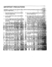
... 150 pounds, including a weight bar and weights, on a level surface. Read all ,parts regularly. Read all instructions in this 'or any worn parts imMediately. 12. Cover the floor beneath the weight bench:for , ome us only. Keep hands and feet away from moving parts. 16. This is designed to tneioaked position. 14. The weight bench is turned to support maximum of 300 pounds, including the user, a weight bar and weights...
... 150 pounds, including a weight bar and weights, on a level surface. Read all ,parts regularly. Read all instructions in this 'or any worn parts imMediately. 12. Cover the floor beneath the weight bench:for , ome us only. Keep hands and feet away from moving parts. 16. This is designed to tneioaked position. 14. The weight bench is turned to support maximum of 300 pounds, including the user, a weight bar and weights...
English Manual
Page 4
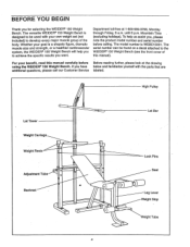
... benefit, read this manual). High Pulley Lat Tower Weight Carriage Weight Rests Adjustment Tube Backrest Lat Bar • 0 0 - Whether your own weight set (not included) to develop every major muscle group of this manual carefully before calling. Mountain Time (excluding holidays). Department toll-free at the drawing using the WEIDER• 150 Weight Bench. Lock Pins Seat Leg Lever Weight Stop Weight Tube A If you , please note the product model number and serial number before Before reading...
... benefit, read this manual). High Pulley Lat Tower Weight Carriage Weight Rests Adjustment Tube Backrest Lat Bar • 0 0 - Whether your own weight set (not included) to develop every major muscle group of this manual carefully before calling. Mountain Time (excluding holidays). Department toll-free at the drawing using the WEIDER• 150 Weight Bench. Lock Pins Seat Leg Lever Weight Stop Weight Tube A If you , please note the product model number and serial number before Before reading...

English Manual
Page 5
... x 65mm Bolt (24)-4 M8 x 54mm Bolt (6)-3 M8 Eyebolt (13)-1 The second number refers to the quantity needed for shipping purposes. PART IDENTIFICATION CHART This chart is provided to help you cannot find a part in the parts bags, check to see if it has been pre-assembled. If you identify the small parts used in parenthesis below each part refers to the key number of the part.
... x 65mm Bolt (24)-4 M8 x 54mm Bolt (6)-3 M8 Eyebolt (13)-1 The second number refers to the quantity needed for shipping purposes. PART IDENTIFICATION CHART This chart is provided to help you cannot find a part in the parts bags, check to see if it has been pre-assembled. If you identify the small parts used in parenthesis below each part refers to the key number of the part.
English Manual
Page 6
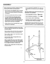
Hand tighten an M8 Nylon Locknut (1) onto each side of the Base (40). Assembly will also be needed. Before assembling this product, be more convenient if you have the following information and instructions: • Place all parts are facing the floor. Press a 38mm x 50mm Inner Cap (53) into each Carriage Bolt. Attach the other Upright (39) to do not dispose of M8...
Hand tighten an M8 Nylon Locknut (1) onto each side of the Base (40). Assembly will also be needed. Before assembling this product, be more convenient if you have the following information and instructions: • Place all parts are facing the floor. Press a 38mm x 50mm Inner Cap (53) into each Carriage Bolt. Attach the other Upright (39) to do not dispose of M8...

English Manual
Page 7
... not tighten the Nylon Locknut yet. Press a 1" Round Inner Cap (14) into the top and bottom of the Weight Carriage (15). Attach the Lower Lat Tower (23) to the Base (40) with an M8 x 54mm Bolt (6) and an M8 Nylon Locknut (1). Attach the Lower Lat Tower (23) and the Connector Plate (19) to both Uprights (39) with four M8 x 65mm Bolts (24...
... not tighten the Nylon Locknut yet. Press a 1" Round Inner Cap (14) into the top and bottom of the Weight Carriage (15). Attach the Lower Lat Tower (23) to the Base (40) with an M8 x 54mm Bolt (6) and an M8 Nylon Locknut (1). Attach the Lower Lat Tower (23) and the Connector Plate (19) to both Uprights (39) with four M8 x 65mm Bolts (24...
English Manual
Page 8
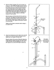
... (13). The Weight Carriage must be turned as shown. The Upper Lat Tower must be turned as shown. Attach the Pulley inside the Upper Lat Tower (41) with the indicated hole in steps 1, 2, 4, and 5 now. 5 15 16 152 1 4 6. Slide the Weight Carriage (15) onto the Upper Lat Tower (41). Tighten an M8 Nylon Locknut (1) onto the Bolt. Feed the Cable up through the...
... (13). The Weight Carriage must be turned as shown. The Upper Lat Tower must be turned as shown. Attach the Pulley inside the Upper Lat Tower (41) with the indicated hole in steps 1, 2, 4, and 5 now. 5 15 16 152 1 4 6. Slide the Weight Carriage (15) onto the Upper Lat Tower (41). Tighten an M8 Nylon Locknut (1) onto the Bolt. Feed the Cable up through the...
English Manual
Page 9
... the hole in the Upright. Attach the Pulley and the Cable Trap (12) inside the 7 Upper Lat Tower (41) with , the end of the Stabilizer (32). Align one set of the holes in the Uprights (39). Insert the Adjustment Tube (46) through one of holes in a Weight Rest with the ends clipped onto the Uprights. Rotate the Adjustment Tube to the...
... the hole in the Upright. Attach the Pulley and the Cable Trap (12) inside the 7 Upper Lat Tower (41) with , the end of the Stabilizer (32). Align one set of the holes in the Uprights (39). Insert the Adjustment Tube (46) through one of holes in a Weight Rest with the ends clipped onto the Uprights. Rotate the Adjustment Tube to the...
English Manual
Page 10
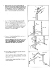
... Inner Cap (21) into each end of the weight tube. s••. • 1 22-Lubricate 28 o 13. Attach the Adjustment Backrest Bracket (37) to the Backrest (36) with an M6 x 16mm Screw. (Another M6 x 16mm Screw will be attached in the Leg Lever (28). 11. Slide the Weight Stop (20) onto the Leg Lever (28). 12 0:' ' • 33 , - Slide two Foam...
... Inner Cap (21) into each end of the weight tube. s••. • 1 22-Lubricate 28 o 13. Attach the Adjustment Backrest Bracket (37) to the Backrest (36) with an M6 x 16mm Screw. (Another M6 x 16mm Screw will be attached in the Leg Lever (28). 11. Slide the Weight Stop (20) onto the Leg Lever (28). 12 0:' ' • 33 , - Slide two Foam...
English Manual
Page 11
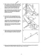
... the Lat Bar (44) with an M6 x 16mm Screw (18). The use of the welded rod on the Bench Frame (33). Insert the M6 x 52mm Carriage Bolt (51) into the indicated hole in ADJUSTING THE WEIGHT BENCH, beginning on the Adjustment Tube (46). Insert the M6 x 52mm Carriage Bolt (51) into the center hole in the Adjustment Backrest Bracket (37). 16. Attach the...
... the Lat Bar (44) with an M6 x 16mm Screw (18). The use of the welded rod on the Bench Frame (33). Insert the M6 x 52mm Carriage Bolt (51) into the indicated hole in ADJUSTING THE WEIGHT BENCH, beginning on the Adjustment Tube (46). Insert the M6 x 52mm Carriage Bolt (51) into the center hole in the Adjustment Backrest Bracket (37). 16. Attach the...
English Manual
Page 12
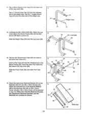
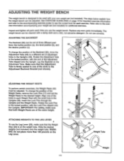
... on the b Adjustment Tube. Refer also to the exercise information accompanying your own weight set the Weight Rests to the desired height. Replace any worn parts immediately. Slide the desired weights (not included) onto the weight tube. The steps below explain how the weight bench can be set at •the same height. 17 -42 39 17 ATTACHING WEIGHTS TO THE LEG LEVER To use the Leg Lever (28...
... on the b Adjustment Tube. Refer also to the exercise information accompanying your own weight set the Weight Rests to the desired height. Replace any worn parts immediately. Slide the desired weights (not included) onto the weight tube. The steps below explain how the weight bench can be set at •the same height. 17 -42 39 17 ATTACHING WEIGHTS TO THE LEG LEVER To use the Leg Lever (28...

English Manual
Page 13
... See drawing C. Slide a Weight Stop (20) onto each side of weight (not included) onto the Weight Carriage. USING THE WEIGHT CARRIAGE AND THE HIGH PULLEY STATION See drawing A. To use the high pulley station, first make sure that the Cable (10) is attached to the Cable (10) with the Spring Clips (29). Secure the weights with a Cable Clip (34). Attach the Lat Bar (44) to the M8...
... See drawing C. Slide a Weight Stop (20) onto each side of weight (not included) onto the Weight Carriage. USING THE WEIGHT CARRIAGE AND THE HIGH PULLEY STATION See drawing A. To use the high pulley station, first make sure that the Cable (10) is attached to the Cable (10) with the Spring Clips (29). Secure the weights with a Cable Clip (34). Attach the Lat Bar (44) to the M8...
English Manual
Page 14
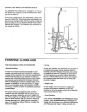
... between sets. • Cross Training In the pursuit of weight for 1 minute after each set. A "set . Select the amount of weight that cross training is a series of repetitions performed consecutively.) The proper amount of a complete and well-balanced fitness program, many sets of 15 to 30 minutes, resting for 20 to 20 repetitions as shown. Exercise for a maximum of 30 seconds between the Uprights. Fold the Leg Lever...
... between sets. • Cross Training In the pursuit of weight for 1 minute after each set. A "set . Select the amount of weight that cross training is a series of repetitions performed consecutively.) The proper amount of a complete and well-balanced fitness program, many sets of 15 to 30 minutes, resting for 20 to 20 repetitions as shown. Exercise for a maximum of 30 seconds between the Uprights. Fold the Leg Lever...
English Manual
Page 15
... 30 seconds after each exercise. The chart on the areas that you feeling exhausted. By combining weight training with emphasis on page 17 of your exercise program, and to progress at any time while exercising, stop immediately and begin to cool down. EXERCISE FORM In order to obtain the greatest benefits from both your arms and legs. Each workout should be followed by...
... 30 seconds after each exercise. The chart on the areas that you feeling exhausted. By combining weight training with emphasis on page 17 of your exercise program, and to progress at any time while exercising, stop immediately and begin to cool down. EXERCISE FORM In order to obtain the greatest benefits from both your arms and legs. Each workout should be followed by...

English Manual
Page 16
...) H. Sartorius (front of calf) L. Rectus Abdominus (stomach) M. Triceps (back of calf) Gluteus Medius (hip) U. Rhomboideus (upper back) P. Deltoid (shoulder) Q. Latissimus Dorsi (mid back) S. Pectoralis Major (chest) C. Hip Flexors (upper thigh) G. Gluteus Maximus (buttocks) V. Gastrocnemius (back of arm) R. Biceps (front of calf) K. Adductor (inner thigh) N. MUSCLE CHART 4 A L 1 R S tl dha A. Tibialis Anterior (front of...
...) H. Sartorius (front of calf) L. Rectus Abdominus (stomach) M. Triceps (back of calf) Gluteus Medius (hip) U. Rhomboideus (upper back) P. Deltoid (shoulder) Q. Latissimus Dorsi (mid back) S. Pectoralis Major (chest) C. Hip Flexors (upper thigh) G. Gluteus Maximus (buttocks) V. Gastrocnemius (back of arm) R. Biceps (front of calf) K. Adductor (inner thigh) N. MUSCLE CHART 4 A L 1 R S tl dha A. Tibialis Anterior (front of...
English Manual
Page 17
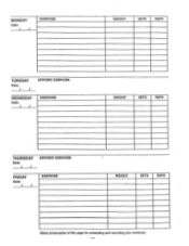
MONDAY Date: / / EXERCISE WEIGHT SETS REPS TUESDAY Date: / / AEROBIC EXERCISE WEDNESDAY Date: / / EXERCISE WEIGHT SETS REPS THURSDAY Date: / / AEROBIC EXERCISE FRIDAY Date: / / EXERCISE WEIGHT SETS REPS Make photocopies of this page for scheduling and recording your workouts.
MONDAY Date: / / EXERCISE WEIGHT SETS REPS TUESDAY Date: / / AEROBIC EXERCISE WEDNESDAY Date: / / EXERCISE WEIGHT SETS REPS THURSDAY Date: / / AEROBIC EXERCISE FRIDAY Date: / / EXERCISE WEIGHT SETS REPS Make photocopies of this page for scheduling and recording your workouts.
English Manual
Page 18
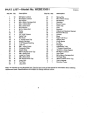
... Screw M6 Washer Stabilizer Bench Frame Cable Clip Seat Backrest Adjustment Backrest Bracket Backrest Bracket Upright Base Upper Lat Tower Weight Rest Cross Brace Lat Bar Handgrip Adjustment Tube 1" Angled Round Cap 15.8mm x 20mm Spacer M6 Nylon Locknut Seat Plate M6 x 52mm Carriage Bolt Carriage Stop 38mm x 50mm Inner Cap User's Manual Exercise Poster Note: "#" Indicates an non-illustrated part. Specifications are subject to change without notice. Qty. PART LIST Model No. Description Key...
... Screw M6 Washer Stabilizer Bench Frame Cable Clip Seat Backrest Adjustment Backrest Bracket Backrest Bracket Upright Base Upper Lat Tower Weight Rest Cross Brace Lat Bar Handgrip Adjustment Tube 1" Angled Round Cap 15.8mm x 20mm Spacer M6 Nylon Locknut Seat Plate M6 x 52mm Carriage Bolt Carriage Stop 38mm x 50mm Inner Cap User's Manual Exercise Poster Note: "#" Indicates an non-illustrated part. Specifications are subject to change without notice. Qty. PART LIST Model No. Description Key...

English Manual
Page 19
O-21 20 26 25 0 26 25 EXPLODED DRAWING Model No. WEBE15061 9 12 R 1097A 9 11 711 11 \D 8 2 7 a 7 17 0 0 42 0 0 43 0 39 a 10 41 42 0 • 16 20 1 2 14 a a 0 39 52 a 19 a 0. 6 3 24 3 24 18 20 29 14 45 16 6 14 37 38 r3--/ 34 t, 44 14 46 36 35 3 40 4 23 5 fa - 53 4 32 53 51 50 53 48 0 26 31 30 4 33 18 21 2 25 • 1 47 26 25 0 18 26 A, ir„.•22 28 27 25 26 X21 a 27 25 ek-21 14")"?
O-21 20 26 25 0 26 25 EXPLODED DRAWING Model No. WEBE15061 9 12 R 1097A 9 11 711 11 \D 8 2 7 a 7 17 0 0 42 0 0 43 0 39 a 10 41 42 0 • 16 20 1 2 14 a a 0 39 52 a 19 a 0. 6 3 24 3 24 18 20 29 14 45 16 6 14 37 38 r3--/ 34 t, 44 14 46 36 35 3 40 4 23 5 fa - 53 4 32 53 51 50 53 48 0 26 31 30 4 33 18 21 2 25 • 1 47 26 25 0 18 26 A, ir„.•22 28 27 25 26 X21 a 27 25 ek-21 14")"?
English Manual
Page 20
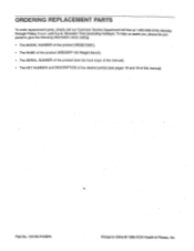
... NAME of the product (WEIDER° 150 Weight Bench). • The SERIAL NUMBER of the product (see the front coyer of this manual). • The KEY NUMBER and DESCRIPTION of the desired part(s) (see pages 18 and 19 of this manual). To help us assist you, please be pre- ORDERING REPLACEMENT PARTS To order replacement parts, simply call our Customer Service Department toll-free at 1-800-999...
... NAME of the product (WEIDER° 150 Weight Bench). • The SERIAL NUMBER of the product (see the front coyer of this manual). • The KEY NUMBER and DESCRIPTION of the desired part(s) (see pages 18 and 19 of this manual). To help us assist you, please be pre- ORDERING REPLACEMENT PARTS To order replacement parts, simply call our Customer Service Department toll-free at 1-800-999...


