
English Manual
Page 2
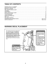
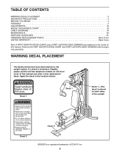
... on the front cover of the warning decal(s). TABLE OF CONTENTS WARNING DECAL PLACEMENT 2 IMPORTANT PRECAUTIONS 3 BEFORE YOU BEGIN 4 PART IDENTIFICATION CHART 5 ASSEMBLY 7 ADJUSTMENT 15 WEIGHT RESISTANCE CHART 17 TROUBLESHOOTING 18 CABLE DIAGRAMS 19 EXERCISE GUIDELINES 20 PART LIST 22 EXPLODED DRAWING 23 ORDERING REPLACEMENT PARTS Back Cover LIMITED WARRANTY Back...
... on the front cover of the warning decal(s). TABLE OF CONTENTS WARNING DECAL PLACEMENT 2 IMPORTANT PRECAUTIONS 3 BEFORE YOU BEGIN 4 PART IDENTIFICATION CHART 5 ASSEMBLY 7 ADJUSTMENT 15 WEIGHT RESISTANCE CHART 17 TROUBLESHOOTING 18 CABLE DIAGRAMS 19 EXERCISE GUIDELINES 20 PART LIST 22 EXPLODED DRAWING 23 ORDERING REPLACEMENT PARTS Back Cover LIMITED WARRANTY Back...
English Manual
Page 3
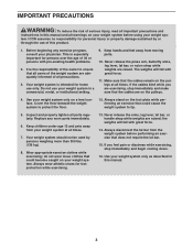
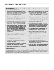
...that the cables are adequately informed of all precautions. 3. Use your weight system only on your weight system before performing an exercise that all users of the weight system are on the pulleys at all times. 7. Your weight system should not be used by or through the use your physician. ...by persons weighing more than 300 lbs. (136 kg). 8. Never release the arms, leg lever, lat bar, or handle strap while weights are raised. the weights will fall with great force. 14. Do not use of this product. 1. tem. If you are exercising, stop immediately and begin ...
...that the cables are adequately informed of all precautions. 3. Use your weight system only on your weight system before performing an exercise that all users of the weight system are on the pulleys at all times. 7. Your weight system should not be used by or through the use your physician. ...by persons weighing more than 300 lbs. (136 kg). 8. Never release the arms, leg lever, lat bar, or handle strap while weights are raised. the weights will fall with great force. 14. Do not use of this product. 1. tem. If you are exercising, stop immediately and begin ...
English Manual
Page 4
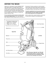
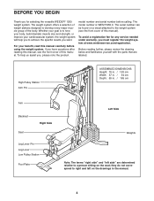
...are shown on the front cover of the serial number decal are labeled in the drawing below. The weight system offers an impressive array of weight stations designed to a person sitting on the drawings in . (135 cm) Butterfly Arm Right Side... Plate Note: The terms "right side" and "left on the seat; For your cardiovascular system, the weight system will help us . they do not correspond to right and left side" are determined relative to develop... please familiarize yourself with you want. To avoid a registration fee for selecting the versatile WEIDER PRO™ 2250 weight system.
...are shown on the front cover of the serial number decal are labeled in the drawing below. The weight system offers an impressive array of weight stations designed to a person sitting on the drawings in . (135 cm) Butterfly Arm Right Side... Plate Note: The terms "right side" and "left on the seat; For your cardiovascular system, the weight system will help us . they do not correspond to right and left side" are determined relative to develop... please familiarize yourself with you want. To avoid a registration fee for selecting the versatile WEIDER PRO™ 2250 weight system.
English Manual
Page 7
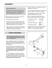
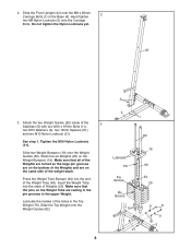
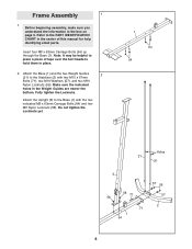
... 67mm Carriage Bolts (14) and two M10 Nylon Locknuts (21). Attach a Stabilizer Foot (51) to do otherwise. • As you assemble the weight bench, make sure that you assemble it will go smoothly. Insert two M10 x 67mm Carriage Bolts (14) up through the Stabilizer (5). Do not dispose ...small holes are oriented as you have a socket set, a set of open-end or closed-end wrenches, or a set of its size, the weight bench should be assembled successfully by almost anyone. Insert two M8 x 65mm Carriage Bolts (1) up through the Base (4). Before beginning assembly, carefully read...
... 67mm Carriage Bolts (14) and two M10 Nylon Locknuts (21). Attach a Stabilizer Foot (51) to do otherwise. • As you assemble the weight bench, make sure that you assemble it will go smoothly. Insert two M10 x 67mm Carriage Bolts (14) up through the Stabilizer (5). Do not dispose ...small holes are oriented as you have a socket set, a set of open-end or closed-end wrenches, or a set of its size, the weight bench should be assembled successfully by almost anyone. Insert two M8 x 65mm Carriage Bolts (1) up through the Base (4). Before beginning assembly, carefully read...
English Manual
Page 8
...M10 Washers (9), two 13mm Spacers (61), and two M10 Nylon Locknuts (21). Make sure that all of the Weights are turned so the large pin grooves are on the bottom of the Weights and are resting in the pin grooves in the Base (4). 2. Slide the Front Upright (42) onto the M8... (21). Hand tighten 2 two M8 Nylon Locknuts (3) onto the Carriage Bolts. Lubricate the insides of the Weight Tube (63). See step 1. Slide two Weight Bumpers (19) onto the Weight Guides (62). Slide the Top Weight onto the Weight Guides (62). 8 4 1 62 Lubricate Pin Pin Groove Pin Groove 19 21 76 63 64 25 9...
...M10 Washers (9), two 13mm Spacers (61), and two M10 Nylon Locknuts (21). Make sure that all of the Weights are turned so the large pin grooves are on the bottom of the Weights and are resting in the pin grooves in the Base (4). 2. Slide the Front Upright (42) onto the M8... (21). Hand tighten 2 two M8 Nylon Locknuts (3) onto the Carriage Bolts. Lubricate the insides of the Weight Tube (63). See step 1. Slide two Weight Bumpers (19) onto the Weight Guides (62). Slide the Top Weight onto the Weight Guides (62). 8 4 1 62 Lubricate Pin Pin Groove Pin Groove 19 21 76 63 64 25 9...
English Manual
Page 9
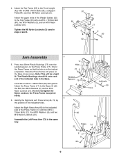
... Spacers 75 4 9 Tube Lubricate 59 6 46 73 Holes 22 9 17 9 22 21 9 21 9 Attach the Right Press Arm (46) to the indicated side of the Weight Guides (62) to the Top Frame (55) with grease. Slide the Press Frame into place on the Press Frame (17). the Press Frame must pivot...
... Spacers 75 4 9 Tube Lubricate 59 6 46 73 Holes 22 9 17 9 22 21 9 21 9 Attach the Right Press Arm (46) to the indicated side of the Weight Guides (62) to the Top Frame (55) with grease. Slide the Press Frame into place on the Press Frame (17). the Press Frame must pivot...
English Manual
Page 13
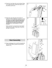
... the Long Cable (23) over the 90mm Pulley (15). Do not overtighten the Nylon Locknut; See the inset drawing. Attach the Backrest (41) to the Weight 67 Tube (63) with an M8 Nylon Locknut (3) and an M8 Washer (8).
... the Long Cable (23) over the 90mm Pulley (15). Do not overtighten the Nylon Locknut; See the inset drawing. Attach the Backrest (41) to the Weight 67 Tube (63) with an M8 Nylon Locknut (3) and an M8 Washer (8).
English Manual
Page 15
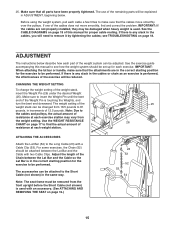
...to 81 pounds, in ADJUSTMENT, beginning below describe how each exercise station may be adjusted. If there is touching the Weights, and turn the bent end downward. The weight setting of the weight stack can be changed from 18.5 pounds to the Short Cable (not shown) in the correct starting position for ... cable a few times to the Long Cable (23) with a Cable Clip (53). IMPORTANT: If the cables are in the same way. see how the weight system should be attached between the Lat Bar and the Cable so the Lat Bar is used with two Cable Clips. The accessories can be...
...to 81 pounds, in ADJUSTMENT, beginning below describe how each exercise station may be adjusted. If there is touching the Weights, and turn the bent end downward. The weight setting of the weight stack can be changed from 18.5 pounds to the Short Cable (not shown) in the correct starting position for ... cable a few times to the Long Cable (23) with a Cable Clip (53). IMPORTANT: If the cables are in the same way. see how the weight system should be attached between the Lat Bar and the Cable so the Lat Bar is used with two Cable Clips. The accessories can be...
English Manual
Page 16
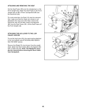
... 53 58 16 Next, remove the Seat Knob (40) and the M8 x 67mm Carriage Bolt (86) from the weight stack. Remove the Weight Pin (not shown) from the Seat Frame (36). Note: The Weight Pin must be removed. ATTACHING AND REMOVING THE SEAT Set the Seat Frame (36) onto the indicated pin on...
... 53 58 16 Next, remove the Seat Knob (40) and the M8 x 67mm Carriage Bolt (86) from the weight stack. Remove the Weight Pin (not shown) from the Seat Frame (36). Note: The Weight Pin must be removed. ATTACHING AND REMOVING THE SEAT Set the Seat Frame (36) onto the indicated pin on...

English Manual
Page 17
... actual resistance at each station. the weight system may vary due to the 12.5 lb. WEIGHT RESISTANCE CHART This chart shows the approximate weight resistance at each butterfly arm. The numbers refer to differences in individual weight plates, as well as friction between the cables, pulleys, and weight guides. WEIGHT PLATES PRESS ARM (lbs.) BUTTERFLY ARM...
... actual resistance at each station. the weight system may vary due to the 12.5 lb. WEIGHT RESISTANCE CHART This chart shows the approximate weight resistance at each butterfly arm. The numbers refer to differences in individual weight plates, as well as friction between the cables, pulleys, and weight guides. WEIGHT PLATES PRESS ARM (lbs.) BUTTERFLY ARM...
English Manual
Page 18
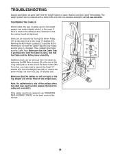
... is used . Additional slack can be removed from the cables by moving the 90mm Pulley (15) to slip off the weight stack. The weight system can stretch slightly when it . Remove the cable and re-install it is felt, the cables should be cleaned with a damp cloth and mild ... to the lower hole in the Long "U"-bracket (57). Make sure that the Cable Trap is positioned to remove the Small "U"bracket (67) from the Weight Tube (63) or remove the 90mm Pulley (15) from the Cable Trap (66), the Pulley, and the Long "U"-bracket. TIGHTENING THE CABLES Woven cable, the...
... is used . Additional slack can be removed from the cables by moving the 90mm Pulley (15) to slip off the weight stack. The weight system can stretch slightly when it . Remove the cable and re-install it is felt, the cables should be cleaned with a damp cloth and mild ... to the lower hole in the Long "U"-bracket (57). Make sure that the Cable Trap is positioned to remove the Small "U"bracket (67) from the Weight Tube (63) or remove the 90mm Pulley (15) from the Cable Trap (66), the Pulley, and the Long "U"-bracket. TIGHTENING THE CABLES Woven cable, the...

English Manual
Page 19
The numbers show the proper routing of the Long Cable (23) and the Short Cable (58). Make sure that the two cables and the cable traps have not been correctly routed, the weight system will not function properly and damage may occur. CABLE DIAGRAMS The cable diagrams show the correct route for each cable. If the cables have been assembled correctly. Use the diagram to make sure that the cable traps do not touch or bind the cables. 5 7 4 1 2 3 Long Cable (23) 6 5 8 Short Cable (58) 4 3 2 1 19
The numbers show the proper routing of the Long Cable (23) and the Short Cable (58). Make sure that the two cables and the cable traps have not been correctly routed, the weight system will not function properly and damage may occur. CABLE DIAGRAMS The cable diagrams show the correct route for each cable. If the cables have been assembled correctly. Use the diagram to make sure that the cable traps do not touch or bind the cables. 5 7 4 1 2 3 Long Cable (23) 6 5 8 Short Cable (58) 4 3 2 1 19
English Manual
Page 20
... photographs showing the correct form for 3 minutes after each set . If you feeling exhausted. Warming up prepares your energy level is the highest. Weight Loss To lose weight, use a low amount of resistance and increase the number of resistance. Schedule your workouts for more strenuous exercise by using high amounts of repetitions...
... photographs showing the correct form for 3 minutes after each set . If you feeling exhausted. Warming up prepares your energy level is the highest. Weight Loss To lose weight, use a low amount of resistance and increase the number of resistance. Schedule your workouts for more strenuous exercise by using high amounts of repetitions...

English Manual
Page 21
...; Rest for three minutes after each set for a muscle building workout. • Rest for one minute after each set for a weight loss workout. out. • Rest for 30 seconds after each set . Include stretches for a short period of each workout is to... Abdominus (stomach) N. Posterior Deltoid (shoulder) R. Spinae Erectors (lower back) U. Gluteus Maximus (buttocks) W. Hamstring (back of arm) S. Never hold your weight and key body measurements at the end of each repetition and inhale during the exertion stroke of time after each repetition should be performed smoothly...
...; Rest for three minutes after each set for a muscle building workout. • Rest for one minute after each set for a weight loss workout. out. • Rest for 30 seconds after each set . Include stretches for a short period of each workout is to... Abdominus (stomach) N. Posterior Deltoid (shoulder) R. Spinae Erectors (lower back) U. Gluteus Maximus (buttocks) W. Hamstring (back of arm) S. Never hold your weight and key body measurements at the end of each repetition and inhale during the exertion stroke of time after each repetition should be performed smoothly...
English Manual
Page 22
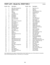
... Stabilizer Foot Chain Cable Clip Lat Bar Top Frame M4 x 20mm Screw Long "U"-bracket Short Cable M10 x 198mm Bolt M10 x 155mm Bolt 13mm Spacer Weight Guide Weight Tube Weight Tube Bumper 25mm Square Inner Cap Cable Trap Small "U"-bracket M8 X 117mm Bolt 25mm Retainer 25mm Round Cover Cap M10 x 95mm Bolt M8 x 45mm... Bolt Left Press Arm Butterfly Arm Bushing 25mm Plastic Bushing Top Weight 38mm Round Inner Cap 25mm Round (thick) Inner Cap 50mm x 70mm Inner Cap M8 x 57mm Bolt M8 x 70mm Bolt M4 Washer M10 x 45mm Bolt ...
... Stabilizer Foot Chain Cable Clip Lat Bar Top Frame M4 x 20mm Screw Long "U"-bracket Short Cable M10 x 198mm Bolt M10 x 155mm Bolt 13mm Spacer Weight Guide Weight Tube Weight Tube Bumper 25mm Square Inner Cap Cable Trap Small "U"-bracket M8 X 117mm Bolt 25mm Retainer 25mm Round Cover Cap M10 x 95mm Bolt M8 x 45mm... Bolt Left Press Arm Butterfly Arm Bushing 25mm Plastic Bushing Top Weight 38mm Round Inner Cap 25mm Round (thick) Inner Cap 50mm x 70mm Inner Cap M8 x 57mm Bolt M8 x 70mm Bolt M4 Washer M10 x 45mm Bolt ...
User Manual
Page 2
...trademark of ICON IP, Inc. 2 Keep hands and fingers clear of the upright Decal 2 Decal 2 WEIDER is missing or illegible, please call the toll-free telephone number on the weight system. Decal 1 Decal 1 Decal 1-This decal is placed on both sides of this manual and order... DRAWING before beginning assembly. TABLE OF CONTENTS WARNING DECAL PLACEMENT 2 IMPORTANT PRECAUTIONS 3 BEFORE YOU BEGIN 4 ASSEMBLY 5 ADJUSTMENTS 16 WEIGHT RESISTANCE CHART 18 CABLE DIAGRAMS 19 MAINTENANCE 20 EXERCISE GUIDELINES 21 ORDERING REPLACEMENT PARTS Back Cover LIMITED WARRANTY Back Cover Note: A ...
...trademark of ICON IP, Inc. 2 Keep hands and fingers clear of the upright Decal 2 Decal 2 WEIDER is missing or illegible, please call the toll-free telephone number on the weight system. Decal 1 Decal 1 Decal 1-This decal is placed on both sides of this manual and order... DRAWING before beginning assembly. TABLE OF CONTENTS WARNING DECAL PLACEMENT 2 IMPORTANT PRECAUTIONS 3 BEFORE YOU BEGIN 4 ASSEMBLY 5 ADJUSTMENTS 16 WEIGHT RESISTANCE CHART 18 CABLE DIAGRAMS 19 MAINTENANCE 20 EXERCISE GUIDELINES 21 ORDERING REPLACEMENT PARTS Back Cover LIMITED WARRANTY Back Cover Note: A ...
User Manual
Page 3
...dizziness while exercising, stop immediately and make sure that the cables are adequately informed of all times. 11. It is the responsibility of the weight system are on a level surface, with a mat beneath it to be used only with dumbbells or any worn parts immediately. 6. Inspect ... increase the resistance. 13. WARNING: Before beginning this manual. 10. Never release the arms, leg lever, lat bar, or handle strap while weights are exercising, stop immediately and begin cooling down. Always wear athletic shoes for persons over the age of 300 pounds. 9. If you are raised...
...dizziness while exercising, stop immediately and make sure that the cables are adequately informed of all times. 11. It is the responsibility of the weight system are on a level surface, with a mat beneath it to be used only with dumbbells or any worn parts immediately. 6. Inspect ... increase the resistance. 13. WARNING: Before beginning this manual. 10. Never release the arms, leg lever, lat bar, or handle strap while weights are exercising, stop immediately and begin cooling down. Always wear athletic shoes for persons over the age of 300 pounds. 9. If you are raised...
User Manual
Page 4
To avoid a registration fee for selecting the versatile WEIDER® 1200 weight system. The serial number can be found on a decal attached to right and left side" are labeled. they do not correspond to the weight system (see the front cover of this manual, see the front cover...you , please note the product model number and serial number before using the weight system. The weight system offers a selection of weight stations designed to achieve the specific results you must register the weight system at www.weiderservice.com/registration. To help you to develop every major...
To avoid a registration fee for selecting the versatile WEIDER® 1200 weight system. The serial number can be found on a decal attached to right and left side" are labeled. they do not correspond to the weight system (see the front cover of this manual, see the front cover...you , please note the product model number and serial number before using the weight system. The weight system offers a selection of weight stations designed to achieve the specific results you must register the weight system at www.weiderservice.com/registration. To help you to develop every major...

User Manual
Page 5
...: • Two adjustable wrenches • One standard screwdriver Hire an Authorized Service Technician To hire an authorized service technician to assemble the weight system, call toll-free 1-800-445-2480. • One phillips screwdriver • One rubber mallet • A small amount of ratchet...page. You may be assembled successfully by assembling the base and the uprights that there is enough clearance to walk around the weight system as possible, we have been pre-attached. Before beginning assembly, make assembly as easy as you will assemble the seats...
...: • Two adjustable wrenches • One standard screwdriver Hire an Authorized Service Technician To hire an authorized service technician to assemble the weight system, call toll-free 1-800-445-2480. • One phillips screwdriver • One rubber mallet • A small amount of ratchet...page. You may be assembled successfully by assembling the base and the uprights that there is enough clearance to walk around the weight system as possible, we have been pre-attached. Before beginning assembly, make assembly as easy as you will assemble the seats...
User Manual
Page 6
... Carriage Bolts (64) and two M8 Nylon Locknuts (58). Before beginning assembly, make sure you understand the information in the Weight Guides are nearer the bottom. Attach the Base (1) and the two Weight Guides 2 (21) to the Base (1) with two M10 x 67mm Bolts (71), two M10 Washers (57), and two M10 Nylon...
... Carriage Bolts (64) and two M8 Nylon Locknuts (58). Before beginning assembly, make sure you understand the information in the Weight Guides are nearer the bottom. Attach the Base (1) and the two Weight Guides 2 (21) to the Base (1) with two M10 x 67mm Bolts (71), two M10 Washers (57), and two M10 Nylon...


