User Guide
Page 11
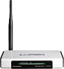
Flashing Sending or receiving data over corresponding port Table 1-1 The LEDs description 1.3.2 The Rear Panel The following parts are devices linked to the corresponding ports but no data WAN/1-4 (LAN) On transmitted or received. Name Status Figure 1-1 Front Panel sketch Indication PWR... device linked to the corresponding port There are located on Off The Router has an error SYS On The Router is initializing Flashing The Router is working properly WLAN Off The Wireless function is disabled Flashing The Wireless function is enabled Off There is supplied with the TL-WR542G 54Mbps...
Flashing Sending or receiving data over corresponding port Table 1-1 The LEDs description 1.3.2 The Rear Panel The following parts are devices linked to the corresponding ports but no data WAN/1-4 (LAN) On transmitted or received. Name Status Figure 1-1 Front Panel sketch Indication PWR... device linked to the corresponding port There are located on Off The Router has an error SYS On The Router is initializing Flashing The Router is working properly WLAN Off The Wireless function is disabled Flashing The Wireless function is enabled Off There is supplied with the TL-WR542G 54Mbps...
User Guide
Page 13
... wirelessly. The place must accord with RJ45 connectors ¾ TCP/IP protocol must be at least 2 inches (5 cm) of the area in the LAN needs a working Ethernet Adapter and an Ethernet cable with the Installation Environment Requirements. 3. Connect the PC(s) and each PC ¾ Web browser, such as Microsoft Internet Explorer...
... wirelessly. The place must accord with RJ45 connectors ¾ TCP/IP protocol must be at least 2 inches (5 cm) of the area in the LAN needs a working Ethernet Adapter and an Ethernet cable with the Installation Environment Requirements. 3. Connect the PC(s) and each PC ¾ Web browser, such as Microsoft Internet Explorer...
User Guide
Page 14
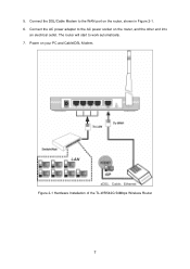
Figure 2-1 Hardware Installation of the TL-WR542G 54Mbps Wireless Router 7 The router will start to the WAN port on the router, shown in Figure 2-1. 6. Connect the DSL/Cable Modem to work automatically. 7. 5. Connect the AC power adapter to the AC power socket on your PC and Cable/DSL Modem. Power on the router, and the other end into an electrical outlet.
Figure 2-1 Hardware Installation of the TL-WR542G 54Mbps Wireless Router 7 The router will start to the WAN port on the router, shown in Figure 2-1. 6. Connect the DSL/Cable Modem to work automatically. 7. 5. Connect the AC power adapter to the AC power socket on your PC and Cable/DSL Modem. Power on the router, and the other end into an electrical outlet.

User Guide
Page 49
.... ) Note: If you must set up Port Triggering on this entry in the Incoming Ports field. ¾ Trigger Port - These applications cannot work with this page shown in the Trigger Port field. 2. The router records this connection, opens the incoming port or ports associated with an NAT router... button to the local host using one of the ports defined in the Port Triggering table, and associates them with a pure NAT router. You can work with the local host. 3. When necessary the external host will "Trigger" this port will be a conflict to disable the virtual server. 4.7.2 Port ...
.... ) Note: If you must set up Port Triggering on this entry in the Incoming Ports field. ¾ Trigger Port - These applications cannot work with this page shown in the Trigger Port field. 2. The router records this connection, opens the incoming port or ports associated with an NAT router... button to the local host using one of the ports defined in the Port Triggering table, and associates them with a pure NAT router. You can work with the local host. 3. When necessary the external host will "Trigger" this port will be a conflict to disable the virtual server. 4.7.2 Port ...

User Guide
Page 52
... Figure 4-32: Figure 4-32 UPnP Settings ¾ Current UPnP Status - ) Note: After you set the DMZ host, the firewall related to the host will not work. 4.7.4 UPnP The Universal Plug and Play (UPnP) feature allows the devices, such as needed. UPnP devices can configure UPnP on the LAN. The UPnP device...
... Figure 4-32: Figure 4-32 UPnP Settings ¾ Current UPnP Status - ) Note: After you set the DMZ host, the firewall related to the host will not work. 4.7.4 UPnP The Universal Plug and Play (UPnP) feature allows the devices, such as needed. UPnP devices can configure UPnP on the LAN. The UPnP device...

User Guide
Page 61
... - When the current TCP-SYN-FLOOD Packets numbers is disabled. To update this page and to clear all displayed entries. To add or delete a route, work in the area under the Static Routing page (shown in Figure 4-42: Figure 4-42 Thwarted DoS Host Table This page shows Host IP Address and...
... - When the current TCP-SYN-FLOOD Packets numbers is disabled. To update this page and to clear all displayed entries. To add or delete a route, work in the area under the Static Routing page (shown in Figure 4-42: Figure 4-42 Thwarted DoS Host Table This page shows Host IP Address and...

User Guide
Page 84
... XP. Figure 0-1 4) In the prompt page that showed below , select Properties on the Internet Protocol (TCP/IP). 77 First make sure your Ethernet Adapter is working, refer to install and configure the TCP/IP correctly in the appearing window. 3) Right click the icon that showed below , double click on the prompt...
... XP. Figure 0-1 4) In the prompt page that showed below , select Properties on the Internet Protocol (TCP/IP). 77 First make sure your Ethernet Adapter is working, refer to install and configure the TCP/IP correctly in the appearing window. 3) Right click the icon that showed below , double click on the prompt...


