
System Reference Manual (primary manual)
Page 11
... ii Safety Information and Caution iii Regulatory Information v FCC Part 68 vi Telephone Consumer Protection Act of 1991 (United States) ..... Configuring Your System Accessing the BIOS Setup Utility 16 Changing the Display's Power Management Settings 17 Configuring the System Board 20 Chapter 3 - Identifying Components Front View 2 Drives 3 Buttons and Switches 4 Indicators...
... ii Safety Information and Caution iii Regulatory Information v FCC Part 68 vi Telephone Consumer Protection Act of 1991 (United States) ..... Configuring Your System Accessing the BIOS Setup Utility 16 Changing the Display's Power Management Settings 17 Configuring the System Board 20 Chapter 3 - Identifying Components Front View 2 Drives 3 Buttons and Switches 4 Indicators...

System Reference Manual (primary manual)
Page 29
Configuring your system. Chapter 2 Configuring Your System This chapter contains information on configuring your system can consist of the following: ❑ Making changes to the BIOS settings ❑ Making changes to the display's power management settings ❑ Changing the system board jumper position 15
Configuring your system. Chapter 2 Configuring Your System This chapter contains information on configuring your system can consist of the following: ❑ Making changes to the BIOS settings ❑ Making changes to the display's power management settings ❑ Changing the system board jumper position 15
System Reference Manual (primary manual)
Page 30
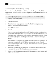
... rebooting the system, save any top-level screen and follow the prompts. 16 VAIO® Reference Manual Accessing the BIOS Setup Utility You must access the BIOS Setup Utility to make changes to the BIOS settings (see "CMOS Setup Options" on BIOS settings). ! Once an item is available. If an item has a triangle ( ) to...plus/minus (+/-) keys to select a menu from any open files and exit the Microsoft® Windows® operating system. 1 Reboot the system. 2 When the Sony logo appears, press F3. Press for setup. 3 Press F2. Use the up and down arrow keys to back out of the screen.
... rebooting the system, save any top-level screen and follow the prompts. 16 VAIO® Reference Manual Accessing the BIOS Setup Utility You must access the BIOS Setup Utility to make changes to the BIOS settings (see "CMOS Setup Options" on BIOS settings). ! Once an item is available. If an item has a triangle ( ) to...plus/minus (+/-) keys to select a menu from any open files and exit the Microsoft® Windows® operating system. 1 Reboot the system. 2 When the Sony logo appears, press F3. Press for setup. 3 Press F2. Use the up and down arrow keys to back out of the screen.

System Reference Manual (primary manual)
Page 43
...and Replacing Components 29 Replacing the Lithium Battery You may need to replace the lithium battery if your computer by selecting Shut Down... The lithium battery has a typical life of all the BIOS options that the settings will refer to this time, and you can hold the charge for a ... on page 16). Otherwise it in the CMOS memory (BIOS setup values and Plug and Play values) may explode if mistreated. Although the computer can skip all remaining steps. 3 Compare all values stored in fire. 1 Reboot your computer consistently loses the date or time settings after which the ...
...and Replacing Components 29 Replacing the Lithium Battery You may need to replace the lithium battery if your computer by selecting Shut Down... The lithium battery has a typical life of all the BIOS options that the settings will refer to this time, and you can hold the charge for a ... on page 16). Otherwise it in the CMOS memory (BIOS setup values and Plug and Play values) may explode if mistreated. Although the computer can skip all remaining steps. 3 Compare all values stored in fire. 1 Reboot your computer consistently loses the date or time settings after which the ...

System Reference Manual (primary manual)
Page 45
If no error message displays, the computer's BIOS settings were retained during the reboot process to exit the BIOS Setup Utility. The computer's BIOS settings are now restored. appears during the reboot sequence, press F2 during the battery replacement and you can skip the remaining steps.... 17 Refer to the list you made in step 3 and restore any non-default BIOS settings (see "CMOS...
If no error message displays, the computer's BIOS settings were retained during the reboot process to exit the BIOS Setup Utility. The computer's BIOS settings are now restored. appears during the reboot sequence, press F2 during the battery replacement and you can skip the remaining steps.... 17 Refer to the list you made in step 3 and restore any non-default BIOS settings (see "CMOS...
System Reference Manual (primary manual)
Page 49
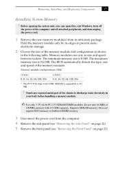
..., 256 DIMM2 0, 8, 16, 32, 64, 128, 256 * The PCV-J150 ships with 133 MHz memory. Does not support EDO memory or buffered DIMM memory. 3 Disconnect the power cord from its edges to prevent staticelectricity damage. 2 Choose the size of the computer and all attached peripherals, and then unplug the power cord... module(s) from the computer. 4 Remove the side panel (see "Removing the Side Panel" on page 22). 5 Remove the front panel (see "Removing the Front Panel" on page 23). SDRAM is 512 MB. Do not mix 66 MHz or 100MHz memory with 64 MB. The BIOS automatically detects the type...
..., 256 DIMM2 0, 8, 16, 32, 64, 128, 256 * The PCV-J150 ships with 133 MHz memory. Does not support EDO memory or buffered DIMM memory. 3 Disconnect the power cord from its edges to prevent staticelectricity damage. 2 Choose the size of the computer and all attached peripherals, and then unplug the power cord... module(s) from the computer. 4 Remove the side panel (see "Removing the Side Panel" on page 22). 5 Remove the front panel (see "Removing the Front Panel" on page 23). SDRAM is 512 MB. Do not mix 66 MHz or 100MHz memory with 64 MB. The BIOS automatically detects the type...

System Reference Manual (primary manual)
Page 79
The Award BIOS setup has five menu items on the menu bar. Text that is not enclosed in this guide. A small triangle ( ) indicates that you can change are ... system. The other options. Chapter 7 CMOS Setup Options This chapter describes each item are shown without brackets directly below the default option in the Award BIOS Setup Utility (see "Accessing the BIOS Setup Utility" on page 16).
The Award BIOS setup has five menu items on the menu bar. Text that is not enclosed in this guide. A small triangle ( ) indicates that you can change are ... system. The other options. Chapter 7 CMOS Setup Options This chapter describes each item are shown without brackets directly below the default option in the Award BIOS Setup Utility (see "Accessing the BIOS Setup Utility" on page 16).
System Reference Manual (primary manual)
Page 81
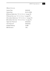
CMOS Setup Options 69 Main Screen System Time [00:00:00] System Date [01/01/2000] Primary Master (see "IDE Sub-Menus" on page 70) Primary Slave (see "IDE Sub-Menus" on page 70) Secondary Master (see "IDE Sub-Menus" on page 70) Secondary Slave (see "IDE Sub-Menus" on page 70) Supervisor Password [Disabled] User Password [Disabled] Installed Memory 64 MB BIOS Revision 1002
CMOS Setup Options 69 Main Screen System Time [00:00:00] System Date [01/01/2000] Primary Master (see "IDE Sub-Menus" on page 70) Primary Slave (see "IDE Sub-Menus" on page 70) Secondary Master (see "IDE Sub-Menus" on page 70) Secondary Slave (see "IDE Sub-Menus" on page 70) Supervisor Password [Disabled] User Password [Disabled] Installed Memory 64 MB BIOS Revision 1002
System Reference Manual (primary manual)
Page 94
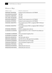
82 VAIO® Reference Manual Memory Map Address range 00000000h-0009FFFFh 000A0000h-000AFFFFh 000B0000h-000BFFFFh 000C0000h-000CBFFFh 000F0000h-000FFFFFh 00100000h-037FFFFFh E8800000h-E8803FFFh E9000000h-E90007FFh E9800000h...-EFFFFFFFh F0000000h-FEBFFFFFh F0000000h-F7FFFFFFh FFEE0000h-FFEFFFFFh FFFE0000h-FFFFFFFFh Default configuration System board extension for ACPI BIOS SiS 730s SiS 730s SiS 730s System board extension for ACPI BIOS System board extension for ACPI BIOS Texas Instruments OHCI-compliant IEEE 1394 host controller Texas Instruments OHCI-compliant IEEE 1394 host controller ...
82 VAIO® Reference Manual Memory Map Address range 00000000h-0009FFFFh 000A0000h-000AFFFFh 000B0000h-000BFFFFh 000C0000h-000CBFFFh 000F0000h-000FFFFFh 00100000h-037FFFFFh E8800000h-E8803FFFh E9000000h-E90007FFh E9800000h...-EFFFFFFFh F0000000h-FEBFFFFFh F0000000h-F7FFFFFFh FFEE0000h-FFEFFFFFh FFFE0000h-FFFFFFFFh Default configuration System board extension for ACPI BIOS SiS 730s SiS 730s SiS 730s System board extension for ACPI BIOS System board extension for ACPI BIOS Texas Instruments OHCI-compliant IEEE 1394 host controller Texas Instruments OHCI-compliant IEEE 1394 host controller ...
System Reference Manual (primary manual)
Page 100
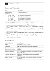
88 VAIO® Reference Manual Drives and Controllers Drive Diskette drive CD-RW drive* CD-RW read... innermost track to 20X at the outermost track (the data transfer standard 1X rate is 150 kbytes/s). System BIOS Make and model ROM Passwords Recovery boot block Power management Advanced features Plug and Play devices Special features Award-...CMOS Flash memory User and supervisor passwords supported Supported APM 1.2 ACPI-1.0 compliant hardware for use with APM and PNP BIOS APIs Supported with steerable DMA channels and interrupts PC-99 compliant, multi-boot, PCI add-in card autoconfigure The...
88 VAIO® Reference Manual Drives and Controllers Drive Diskette drive CD-RW drive* CD-RW read... innermost track to 20X at the outermost track (the data transfer standard 1X rate is 150 kbytes/s). System BIOS Make and model ROM Passwords Recovery boot block Power management Advanced features Plug and Play devices Special features Award-...CMOS Flash memory User and supervisor passwords supported Supported APM 1.2 ACPI-1.0 compliant hardware for use with APM and PNP BIOS APIs Supported with steerable DMA channels and interrupts PC-99 compliant, multi-boot, PCI add-in card autoconfigure The...

System Reference Manual (primary manual)
Page 101
... Clear configuration jumper 62 codes, beeps 77 COM1 port - See SERIAL connector communications, specifications 87 computer lithium battery vii computer safety information ii configuration jumper, CMOS Clear 62 configuring BIOS setup utility 16 power management 17 system board 20 connectors 4-pin on modem card 63 AUX-IN 61 CD-IN 60 ... 55 MOUSE 53 PCI 51 power 52 PRINTER 55 TELEPHONE 63 USB 54 cover, for 88 CMOS - See lithium battery beep codes 77 BIOS Setup Utility 16 BIOS setup utility 16 advanced screen 71 boot screen 73 exit screen 74 main screen 69 options 67 power screen 72 screens 67...
... Clear configuration jumper 62 codes, beeps 77 COM1 port - See SERIAL connector communications, specifications 87 computer lithium battery vii computer safety information ii configuration jumper, CMOS Clear 62 configuring BIOS setup utility 16 power management 17 system board 20 connectors 4-pin on modem card 63 AUX-IN 61 CD-IN 60 ... 55 MOUSE 53 PCI 51 power 52 PRINTER 55 TELEPHONE 63 USB 54 cover, for 88 CMOS - See lithium battery beep codes 77 BIOS Setup Utility 16 BIOS setup utility 16 advanced screen 71 boot screen 73 exit screen 74 main screen 69 options 67 power screen 72 screens 67...

System Reference Manual (primary manual)
Page 103
... IN connector 57 memory module connector 50 MIC connector 57 MONITOR connector 55 MOUSE 53 See Also I/O slot slot cover, removing 40 specifications audio 87 BIOS 88 communications 87 drives and controllers 88 graphics 86 I /O connectors 9 icons 7 recording ii regulatory information v removing add-in card 28 front panel 23 memory module... - See Also system memory memory module connector 50 removing 33 specifications for 85 R radio interference v RAM - See processor model numbers ii modem - See SERIAL setup, BIOS 16 side panel 25 removing 22 slot - memory map memory -
... IN connector 57 memory module connector 50 MIC connector 57 MONITOR connector 55 MOUSE 53 See Also I/O slot slot cover, removing 40 specifications audio 87 BIOS 88 communications 87 drives and controllers 88 graphics 86 I /O connectors 9 icons 7 recording ii regulatory information v removing add-in card 28 front panel 23 memory module... - See Also system memory memory module connector 50 removing 33 specifications for 85 R radio interference v RAM - See processor model numbers ii modem - See SERIAL setup, BIOS 16 side panel 25 removing 22 slot - memory map memory -


