System Reference Manual (primary manual)
Page 2
... additional charge. Notice to change without notice. Use of such software is a registered trademark of Advanced Micro Devices. IN NO EVENT SHALL SONY ELECTRONICS INC. Sony, VAIO, the VAIO logo, and i.LINK are trademarks or registered trademarks of IBM Corporation. Owner's Record The model number and serial number are registered trademarks of your Sony Service Center. Microsoft, Windows, and the Windows logo are located on the back of Microsoft...
... additional charge. Notice to change without notice. Use of such software is a registered trademark of Advanced Micro Devices. IN NO EVENT SHALL SONY ELECTRONICS INC. Sony, VAIO, the VAIO logo, and i.LINK are trademarks or registered trademarks of IBM Corporation. Owner's Record The model number and serial number are registered trademarks of your Sony Service Center. Microsoft, Windows, and the Windows logo are located on the back of Microsoft...
System Reference Manual (primary manual)
Page 5
... result in a residential installation. Only peripherals (computer input/output devices, terminals, printers, etc.) that interference will not occur in interference to result in a particular installation. Regulatory Information Declaration of FCC Rules. This device complies with noncompliant peripherals is likely to radio and television reception. Operation with Part 15 of Conformity Trade Name: SONY Model No.: PCV-J150 Responsible Party: Sony Electronics Inc.
... result in a residential installation. Only peripherals (computer input/output devices, terminals, printers, etc.) that interference will not occur in interference to result in a particular installation. Regulatory Information Declaration of FCC Rules. This device complies with noncompliant peripherals is likely to radio and television reception. Operation with Part 15 of Conformity Trade Name: SONY Model No.: PCV-J150 Responsible Party: Sony Electronics Inc.

System Reference Manual (primary manual)
Page 11
... Part 68 vi Telephone Consumer Protection Act of 1991 (United States) ..... Removing, Installing, and Replacing Components Removing the Side Panel 22 Removing the Front Panel 23 Replacing the Front Panel 24 Replacing the Side Panel 25 xi vi Telephone Consumer Guidelines (Canada vii DISPOSAL OF LITHIUM BATTERY vii INDUSTRY CANADA NOTICE viii AVIS DE L'INDUSTRIE CANADA viii Chapter 1 - Configuring Your System Accessing the BIOS Setup Utility 16 Changing the Display's Power Management Settings...
... Part 68 vi Telephone Consumer Protection Act of 1991 (United States) ..... Removing, Installing, and Replacing Components Removing the Side Panel 22 Removing the Front Panel 23 Replacing the Front Panel 24 Replacing the Side Panel 25 xi vi Telephone Consumer Guidelines (Canada vii DISPOSAL OF LITHIUM BATTERY vii INDUSTRY CANADA NOTICE viii AVIS DE L'INDUSTRIE CANADA viii Chapter 1 - Configuring Your System Accessing the BIOS Setup Utility 16 Changing the Display's Power Management Settings...
System Reference Manual (primary manual)
Page 12
... Exit Screen 74 Chapter 8 - System Board Connectors 48 Front Panel Header 48 Diskette Drive Connector 49 Memory Module (DIMM) Connectors 50 PCI Slot Connectors 51 IDE Connectors 52 Power Connector 52 KEYBOARD and MOUSE Connectors 53 USB Connectors 54 PRINTER, i.LINK, and MONITOR Connectors 55 SERIAL, HEADPHONES, LINE IN, MIC Connectors 57 Fan Connector 59 CD-IN Connector 60 AUX-IN Connector 61 Configuration Jumper 62 Chapter 5 - Ethernet Card Chapter 7 - xii VAIO® Reference Manual Installing an Add-In Card 26 Removing an Add-in Card 28 Replacing the Lithium Battery...
... Exit Screen 74 Chapter 8 - System Board Connectors 48 Front Panel Header 48 Diskette Drive Connector 49 Memory Module (DIMM) Connectors 50 PCI Slot Connectors 51 IDE Connectors 52 Power Connector 52 KEYBOARD and MOUSE Connectors 53 USB Connectors 54 PRINTER, i.LINK, and MONITOR Connectors 55 SERIAL, HEADPHONES, LINE IN, MIC Connectors 57 Fan Connector 59 CD-IN Connector 60 AUX-IN Connector 61 Configuration Jumper 62 Chapter 5 - Ethernet Card Chapter 7 - xii VAIO® Reference Manual Installing an Add-In Card 26 Removing an Add-in Card 28 Replacing the Lithium Battery...

System Reference Manual (primary manual)
Page 34
Access to specific setup fields is stored in CMOS. The CMOS and Non-Volatile RAM (NVRAM) settings are cleared. ✍ The configuration jumpers should never need changing unless otherwise directed by a technical support or service technician. ! Before opening the system, save any open files, exit the Microsoft® Windows® operating system, turn off the power of reserved jumper blocks (do not change). No other parameters are only cleared if the checksum test returns false. Configuring the...
Access to specific setup fields is stored in CMOS. The CMOS and Non-Volatile RAM (NVRAM) settings are cleared. ✍ The configuration jumpers should never need changing unless otherwise directed by a technical support or service technician. ! Before opening the system, save any open files, exit the Microsoft® Windows® operating system, turn off the power of reserved jumper blocks (do not change). No other parameters are only cleared if the checksum test returns false. Configuring the...
System Reference Manual (primary manual)
Page 40
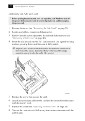
..., save any open files, exit Windows, turn off the power of the computer and all attached peripherals, and then unplug the power cord. 1 Remove the cover (see "Removing the Side Panel" on page 22). 2 Locate an available expansion slot connector. 3 Remove the slot cover adjacent to the card (see the instructions that came with the add-in card into the slot at the bottom of the bracket fits into the PCI slot connector. Use a gentle...
..., save any open files, exit Windows, turn off the power of the computer and all attached peripherals, and then unplug the power cord. 1 Remove the cover (see "Removing the Side Panel" on page 22). 2 Locate an available expansion slot connector. 3 Remove the slot cover adjacent to the card (see the instructions that came with the add-in card into the slot at the bottom of the bracket fits into the PCI slot connector. Use a gentle...

System Reference Manual (primary manual)
Page 43
... power the CMOS memory. ! Although the computer can hold the charge for a short time while replacing the battery, it off the computer and unplug the power cord. 7 Remove the side panel (see "Accessing the BIOS Setup Utility" on page 67). from the main menu using the right arrow key. 5 Press Enter, type Y when prompted to discard changes, then press Enter to exit the BIOS Setup Utility. 6 Turn off . Do not disassemble it in the CMOS memory (BIOS setup values and Plug...
... power the CMOS memory. ! Although the computer can hold the charge for a short time while replacing the battery, it off the computer and unplug the power cord. 7 Remove the side panel (see "Accessing the BIOS Setup Utility" on page 67). from the main menu using the right arrow key. 5 Press Enter, type Y when prompted to discard changes, then press Enter to exit the BIOS Setup Utility. 6 Turn off . Do not disassemble it in the CMOS memory (BIOS setup values and Plug...
System Reference Manual (primary manual)
Page 46
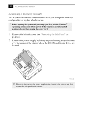
32 VAIO® Reference Manual Removing a Memory Module You may need to the chassis. Before opening the system unit, save any open files, exit the Windows® operating system, turn off the power of the computer and all attached peripherals, and then unplug the power cord. 1 Remove the left side cover (see "Removing the Side Panel" on page 22). 2 Remove the power supply by lifting it up and resting it upside...
32 VAIO® Reference Manual Removing a Memory Module You may need to the chassis. Before opening the system unit, save any open files, exit the Windows® operating system, turn off the power of the computer and all attached peripherals, and then unplug the power cord. 1 Remove the left side cover (see "Removing the Side Panel" on page 22). 2 Remove the power supply by lifting it up and resting it upside...
System Reference Manual (primary manual)
Page 48
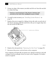
... the module in memory and will configure itself accordingly when you turn on the computer. 34 VAIO® Reference Manual 5 Grasp one edge of the chassis to discharge static electricity in your body before handling the memory module. 6 To install system memory, see "Replacing the Side Panel" on page 25). 9 Reconnect the power cord and turn on the computer. Touch any change in a static-free bag. !
... the module in memory and will configure itself accordingly when you turn on the computer. 34 VAIO® Reference Manual 5 Grasp one edge of the chassis to discharge static electricity in your body before handling the memory module. 6 To install system memory, see "Replacing the Side Panel" on page 25). 9 Reconnect the power cord and turn on the computer. Touch any change in a static-free bag. !

System Reference Manual (primary manual)
Page 52
Your computer automatically recognizes the extra memory and will configure itself accordingly when you turn on the computer. 38 VAIO® Reference Manual 11 Replace the power supply by sliding it down the rails on each side of the chassis opening until the metal tab on the computer. No further action is required. Tab fits into slot in CD-RW drive AUR002.VSD 12 Replace the side panel (see "Replacing the Side Panel" on page 25). 13 Reconnect the power cord and turn on the power supply slips into the slot in the CD-RW drive.
Your computer automatically recognizes the extra memory and will configure itself accordingly when you turn on the computer. 38 VAIO® Reference Manual 11 Replace the power supply by sliding it down the rails on each side of the chassis opening until the metal tab on the computer. No further action is required. Tab fits into slot in CD-RW drive AUR002.VSD 12 Replace the side panel (see "Replacing the Side Panel" on page 25). 13 Reconnect the power cord and turn on the power supply slips into the slot in the CD-RW drive.
System Reference Manual (primary manual)
Page 55
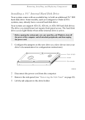
... power cord. 1 Configure the jumpers on page 22). 4 Lift the tab adjacent to the drive holder. Power connector Jumpers Drive connector KY0084.VSD 2 Disconnect the power cord from the computer. 3 Remove the side panel (see your drive's documentation for configuration instructions). Your system can support ATA-33, ATA-66, or ATA-100 hard disk drives. The drive you install must not require front panel access. The hard disk drive access light blinks when either internal drive is active. ! Removing, Installing, and Replacing Components 41 Installing a 3½" Internal Hard Disk Drive...
... power cord. 1 Configure the jumpers on page 22). 4 Lift the tab adjacent to the drive holder. Power connector Jumpers Drive connector KY0084.VSD 2 Disconnect the power cord from the computer. 3 Remove the side panel (see your drive's documentation for configuration instructions). Your system can support ATA-33, ATA-66, or ATA-100 hard disk drives. The drive you install must not require front panel access. The hard disk drive access light blinks when either internal drive is active. ! Removing, Installing, and Replacing Components 41 Installing a 3½" Internal Hard Disk Drive...

System Reference Manual (primary manual)
Page 59
Chapter 4 System Board This chapter identifies each component on the system board and provides a detailed description of each connector, jumper, and switch on the system board. Keyboard, Mouse CPU CPU Fan Memory USB1/2/3 Power Supply Fan Parallel (top), i.Link, Monitor IEEE 1394 Header (not used) Serial (top) MicIn, Line In, Line Out Video (not used) CD-In (to CD-RW drive) Aux-In (not used) Wake-On-LAN (not used) PCI slot 4 PCI slot 3 PCI slot 2 PCI slot 1 CMOS Clear Normal 1-2 Clear 2-3 Power Supply Diskette Secondary IDE Primary IDE VIRQ Battery Front panel header OM04581.VS 47
Chapter 4 System Board This chapter identifies each component on the system board and provides a detailed description of each connector, jumper, and switch on the system board. Keyboard, Mouse CPU CPU Fan Memory USB1/2/3 Power Supply Fan Parallel (top), i.Link, Monitor IEEE 1394 Header (not used) Serial (top) MicIn, Line In, Line Out Video (not used) CD-In (to CD-RW drive) Aux-In (not used) Wake-On-LAN (not used) PCI slot 4 PCI slot 3 PCI slot 2 PCI slot 1 CMOS Clear Normal 1-2 Clear 2-3 Power Supply Diskette Secondary IDE Primary IDE VIRQ Battery Front panel header OM04581.VS 47
System Reference Manual (primary manual)
Page 81
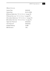
CMOS Setup Options 69 Main Screen System Time [00:00:00] System Date [01/01/2000] Primary Master (see "IDE Sub-Menus" on page 70) Primary Slave (see "IDE Sub-Menus" on page 70) Secondary Master (see "IDE Sub-Menus" on page 70) Secondary Slave (see "IDE Sub-Menus" on page 70) Supervisor Password [Disabled] User Password [Disabled] Installed Memory 64 MB BIOS Revision 1002
CMOS Setup Options 69 Main Screen System Time [00:00:00] System Date [01/01/2000] Primary Master (see "IDE Sub-Menus" on page 70) Primary Slave (see "IDE Sub-Menus" on page 70) Secondary Master (see "IDE Sub-Menus" on page 70) Secondary Slave (see "IDE Sub-Menus" on page 70) Supervisor Password [Disabled] User Password [Disabled] Installed Memory 64 MB BIOS Revision 1002

System Reference Manual (primary manual)
Page 93
... Standard floppy disk controller Primary IDE controller (dual FIFO) SiS 5513 dual PCI IDE controller Standard floppy disk controller Communications port (COM1) Motherboard resources Motherboard resources PCI bus WDM communication device WDM communication device Realtek RTL8139 (A/B/C/8130) PCI Fast Ethernet NIC SiS Accelerated Graphics Port SiS 730s SiS 7018 audio driver Primary IDE controller (dual FIFO) SiS 5513 dual PCI IDE controller Secondary IDE controller (dual FIFO) Motherboard resources Motherboard resources ✍ I/O addresses that may be used by add-in cards are not listed.
... Standard floppy disk controller Primary IDE controller (dual FIFO) SiS 5513 dual PCI IDE controller Standard floppy disk controller Communications port (COM1) Motherboard resources Motherboard resources PCI bus WDM communication device WDM communication device Realtek RTL8139 (A/B/C/8130) PCI Fast Ethernet NIC SiS Accelerated Graphics Port SiS 730s SiS 7018 audio driver Primary IDE controller (dual FIFO) SiS 5513 dual PCI IDE controller Secondary IDE controller (dual FIFO) Motherboard resources Motherboard resources ✍ I/O addresses that may be used by add-in cards are not listed.

System Reference Manual (primary manual)
Page 95
... 7001 PCI to USB open host controller 09 WDM communication device 09 ACPI IRQ holder for PCI IRQ steering 09 SCI IRQ used by ACPI bus 10 ACPI IRQ holder for PCI IRQ steering 10 SiS 7018 audio driver 11 SiS 730s 11 ACPI IRQ holder for PCI IRQ steering 12 PS/2® compatible mouse port 13 Numeric data processor 14 Primary IDE controller (dual FIFO...
... 7001 PCI to USB open host controller 09 WDM communication device 09 ACPI IRQ holder for PCI IRQ steering 09 SCI IRQ used by ACPI bus 10 ACPI IRQ holder for PCI IRQ steering 10 SiS 7018 audio driver 11 SiS 730s 11 ACPI IRQ holder for PCI IRQ steering 12 PS/2® compatible mouse port 13 Numeric data processor 14 Primary IDE controller (dual FIFO...
System Reference Manual (primary manual)
Page 98
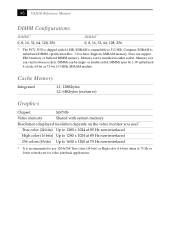
or double-sided. Cache Memory Integrated L1: 128Kbytes L2: 64Kbytes (exclusive) Graphics Chipset SiS730S Video memory Shared with 64 MB. Does not support EDO memory or buffered DIMM memory. Computer SDRAM is expandable to use )* True color (24 bits) Up to ...video playback applications. Memory size can be installed in either socket. 86 VAIO® Reference Manual DIMM Configurations DIMM1* 0, 8, 16, 32, 64, 128, 256 DIMM2* 0, 8, 16, 32, 64, 128, 256 * The PCV-J150 is shipped with system memory Resolution (displayed resolution depends on the video monitor you use...
or double-sided. Cache Memory Integrated L1: 128Kbytes L2: 64Kbytes (exclusive) Graphics Chipset SiS730S Video memory Shared with 64 MB. Does not support EDO memory or buffered DIMM memory. Computer SDRAM is expandable to use )* True color (24 bits) Up to ...video playback applications. Memory size can be installed in either socket. 86 VAIO® Reference Manual DIMM Configurations DIMM1* 0, 8, 16, 32, 64, 128, 256 DIMM2* 0, 8, 16, 32, 64, 128, 256 * The PCV-J150 is shipped with system memory Resolution (displayed resolution depends on the video monitor you use...
System Reference Manual (primary manual)
Page 100
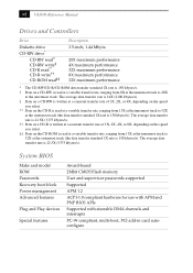
...BIOS Make and model ROM Passwords Recovery boot block Power management Advanced features Plug and Play devices Special features Award-based 2Mbit CMOS Flash memory User and supervisor passwords supported Supported APM 1.2 ACPI-1.0 compliant hardware for use with APM and PNP BIOS APIs Supported with steerable DMA channels and interrupts PC-99 compliant, multi-boot, PCI add-in card... 150 kbytes/s). 88 VAIO® Reference Manual Drives and Controllers Drive Diskette drive CD-RW drive* CD-RW read† CD-RW write‡ CD-R read** CD-R write†† CD-ROM read‡‡ ...
...BIOS Make and model ROM Passwords Recovery boot block Power management Advanced features Plug and Play devices Special features Award-based 2Mbit CMOS Flash memory User and supervisor passwords supported Supported APM 1.2 ACPI-1.0 compliant hardware for use with APM and PNP BIOS APIs Supported with steerable DMA channels and interrupts PC-99 compliant, multi-boot, PCI add-in card... 150 kbytes/s). 88 VAIO® Reference Manual Drives and Controllers Drive Diskette drive CD-RW drive* CD-RW read† CD-RW write‡ CD-R read** CD-R write†† CD-ROM read‡‡ ...

System Reference Manual (primary manual)
Page 101
... 63 USB 54 cover, for 88 display, power management 17 89 Index A add-in card installing 26 removing 28 address map, system 80 audio specifications 87 AUX-IN connector 61 B battery - See Also BIOS CMOS Clear configuration jumper 62 codes, beeps 77 COM1 port - See processor D DIMM - See lithium battery beep codes 77 BIOS Setup Utility 16 BIOS setup utility 16 advanced screen 71 boot screen 73 exit screen 74 main screen 69 options 67 power screen 72 screens 67 BIOS specifications 88 C card, modem 63 cards Ethernet 65, 87 CD-IN connector 60 CD-RW drive location...
... 63 USB 54 cover, for 88 display, power management 17 89 Index A add-in card installing 26 removing 28 address map, system 80 audio specifications 87 AUX-IN connector 61 B battery - See Also BIOS CMOS Clear configuration jumper 62 codes, beeps 77 COM1 port - See processor D DIMM - See lithium battery beep codes 77 BIOS Setup Utility 16 BIOS setup utility 16 advanced screen 71 boot screen 73 exit screen 74 main screen 69 options 67 power screen 72 screens 67 BIOS specifications 88 C card, modem 63 cards Ethernet 65, 87 CD-IN connector 60 CD-RW drive location...

System Reference Manual (primary manual)
Page 102
... E error messages beep codes 77 PCI configuration 78 Ethernet card 65, 87 Ethernet connector 12, 65 expansion slots 13 specifications for 88 installing 3½" hard disk drive 42 add-in card 26 system memory 36 interference v IRQ settings 83 J jumper - See modem card fax/modem - See Also communications FCC Part 68 vi front panel removing 23 replacing 24 front panel header 48 front view 2 buttons and switches 4 connectors 5 drives 3 indicators 5 G graphics controller - See Also slots F fan connectors 59 CPU-FAN 59 PWR-FAN 59 fax card - See system board K KEYBOARD connector 9, 53...
... E error messages beep codes 77 PCI configuration 78 Ethernet card 65, 87 Ethernet connector 12, 65 expansion slots 13 specifications for 88 installing 3½" hard disk drive 42 add-in card 26 system memory 36 interference v IRQ settings 83 J jumper - See modem card fax/modem - See Also communications FCC Part 68 vi front panel removing 23 replacing 24 front panel header 48 front view 2 buttons and switches 4 connectors 5 drives 3 indicators 5 G graphics controller - See Also slots F fan connectors 59 CPU-FAN 59 PWR-FAN 59 fax card - See system board K KEYBOARD connector 9, 53...

System Reference Manual (primary manual)
Page 103
See processor model numbers ii modem - See SERIAL setup, BIOS 16 side panel 25 removing 22 slot - See Also I/O slot slot cover, removing 40 specifications audio 87 BIOS 88 communications 87 drives and controllers 88 graphics 86 I /O connectors 9 icons 7 recording ii regulatory information v removing add-in card 28 front panel 23 memory module 33 side panel 22 91 slot cover 40 replacing 25 front panel 24 lithium battery 30 side panel 25 resolution - memory map memory - See Also display MONITOR connector 10, 55 MOUSE connector 9, 53 N notice to users ii P panel, front...
See processor model numbers ii modem - See SERIAL setup, BIOS 16 side panel 25 removing 22 slot - See Also I/O slot slot cover, removing 40 specifications audio 87 BIOS 88 communications 87 drives and controllers 88 graphics 86 I /O connectors 9 icons 7 recording ii regulatory information v removing add-in card 28 front panel 23 memory module 33 side panel 22 91 slot cover 40 replacing 25 front panel 24 lithium battery 30 side panel 25 resolution - memory map memory - See Also display MONITOR connector 10, 55 MOUSE connector 9, 53 N notice to users ii P panel, front...

