System Reference Manual (primary manual)
Page 26
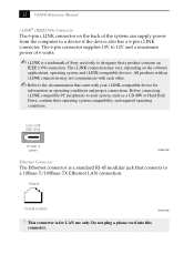
...; Refer to the documentation that connects to a 10Base-T/100Base-TX Ethernet LAN connection. Ethernet On back of the system can supply power from the computer to designate that a product contains an IEEE 1394 connection. The i.LINK connection may not communicate with your i.LINK-compatible device... not plug a phone cord into this connector. 12 VAIO® Reference Manual i.LINK® (IEEE1394) Connector The 6-pin i.LINK connector on the back of system KY0100.VSD ! The 6-pin connector supplies 10V to 12V and a maximum power of Sony used only to a device if the device also has...
...; Refer to the documentation that connects to a 10Base-T/100Base-TX Ethernet LAN connection. Ethernet On back of the system can supply power from the computer to designate that a product contains an IEEE 1394 connection. The i.LINK connection may not communicate with your i.LINK-compatible device... not plug a phone cord into this connector. 12 VAIO® Reference Manual i.LINK® (IEEE1394) Connector The 6-pin i.LINK connector on the back of system KY0100.VSD ! The 6-pin connector supplies 10V to 12V and a maximum power of Sony used only to a device if the device also has...
System Reference Manual (primary manual)
Page 36
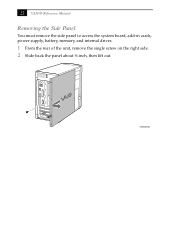
22 VAIO® Reference Manual Removing the Side Panel You must remove the side panel to access the system board, add-in cards, power supply, battery, memory, and internal drives. 1 From the rear of the unit, remove the single screw on the right side. 2 Slide back the panel about ½ inch, then lift out. KY0064B.VSD
22 VAIO® Reference Manual Removing the Side Panel You must remove the side panel to access the system board, add-in cards, power supply, battery, memory, and internal drives. 1 From the rear of the unit, remove the single screw on the right side. 2 Slide back the panel about ½ inch, then lift out. KY0064B.VSD
System Reference Manual (primary manual)
Page 46
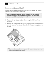
... open files, exit the Windows® operating system, turn off the power of the computer and all attached peripherals, and then unplug the power cord. 1 Remove the left side cover (see "Removing the Side Panel" on page 22). 2 Remove the power supply by lifting it up and resting it upside down over the corner... of the chassis where the CD-RW and floppy drives are located. AUR001.VSD ✍ The screw that secures the power supply to the chassis is the same screw that secures the side panel to remove a memory module if you change the memory configuration or replace a ...
... open files, exit the Windows® operating system, turn off the power of the computer and all attached peripherals, and then unplug the power cord. 1 Remove the left side cover (see "Removing the Side Panel" on page 22). 2 Remove the power supply by lifting it up and resting it upside down over the corner... of the chassis where the CD-RW and floppy drives are located. AUR001.VSD ✍ The screw that secures the power supply to the chassis is the same screw that secures the side panel to remove a memory module if you change the memory configuration or replace a ...
System Reference Manual (primary manual)
Page 48
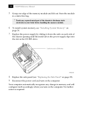
...the CD-RW drive. 34 VAIO® Reference Manual 5 Grasp one edge of the chassis opening until the metal tab on the power supply slips into slot in CD-RW drive AUR002.VSD 8 Replace the side panel (see "Installing System Memory" on page 36. 7 Replace the power supply by sliding it down the ...rails on each side of the memory module and lift out. Store the module in your body before handling the memory module. 6 To install system memory, see "Replacing the Side Panel" on page 25). 9 Reconnect the power cord and turn on the computer. Your computer ...
...the CD-RW drive. 34 VAIO® Reference Manual 5 Grasp one edge of the chassis opening until the metal tab on the power supply slips into slot in CD-RW drive AUR002.VSD 8 Replace the side panel (see "Installing System Memory" on page 36. 7 Replace the power supply by sliding it down the ...rails on each side of the memory module and lift out. Store the module in your body before handling the memory module. 6 To install system memory, see "Replacing the Side Panel" on page 25). 9 Reconnect the power cord and turn on the computer. Your computer ...
System Reference Manual (primary manual)
Page 50
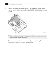
AUR001.VSD ✍ The screw that secures the power supply to the chassis is the same screw that secures the side panel to the chassis. 7 If necessary, remove the memory module you wish to replace (see "Removing a Memory Module" on page 33). 36 VAIO® Reference Manual 6 Remove the power supply by lifting it up and rest it upside down over the corner of the chassis where the CD-RW and floppy drives are located.
AUR001.VSD ✍ The screw that secures the power supply to the chassis is the same screw that secures the side panel to the chassis. 7 If necessary, remove the memory module you wish to replace (see "Removing a Memory Module" on page 33). 36 VAIO® Reference Manual 6 Remove the power supply by lifting it up and rest it upside down over the corner of the chassis where the CD-RW and floppy drives are located.

System Reference Manual (primary manual)
Page 52
Tab fits into the slot in CD-RW drive AUR002.VSD 12 Replace the side panel (see "Replacing the Side Panel" on page 25). 13 Reconnect the power cord and turn on the computer. No further action is required. Your computer automatically recognizes the extra memory and will configure itself accordingly when you turn on the computer. 38 VAIO® Reference Manual 11 Replace the power supply by sliding it down the rails on each side of the chassis opening until the metal tab on the power supply slips into slot in the CD-RW drive.
Tab fits into the slot in CD-RW drive AUR002.VSD 12 Replace the side panel (see "Replacing the Side Panel" on page 25). 13 Reconnect the power cord and turn on the computer. No further action is required. Your computer automatically recognizes the extra memory and will configure itself accordingly when you turn on the computer. 38 VAIO® Reference Manual 11 Replace the power supply by sliding it down the rails on each side of the chassis opening until the metal tab on the power supply slips into slot in the CD-RW drive.
System Reference Manual (primary manual)
Page 56
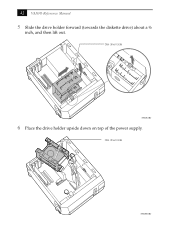
42 VAIO® Reference Manual 5 Slide the drive holder forward (towards the diskette drive) about a ½ inch, and then lift out. Disk drive holder KY0081B.VSD Disk drive holder KY0081.VSD 6 Place the drive holder upside down on top of the power supply.
42 VAIO® Reference Manual 5 Slide the drive holder forward (towards the diskette drive) about a ½ inch, and then lift out. Disk drive holder KY0081B.VSD Disk drive holder KY0081.VSD 6 Place the drive holder upside down on top of the power supply.
System Reference Manual (primary manual)
Page 64
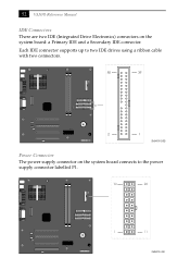
52 VAIO® Reference Manual IDE Connectors There are two IDE (Integrated Drive Electronics) connectors on the system board connects to the power supply connector labelled P1. 10 20 1 11 OM04701I.VSD Each IDE connector supports up to two IDE drives using a ribbon cable with two connectors. 40 39 2 1 OM04701G.VSD Power Connector The power supply connector on the system board: a Primary IDE and a Secondary IDE connector.
52 VAIO® Reference Manual IDE Connectors There are two IDE (Integrated Drive Electronics) connectors on the system board connects to the power supply connector labelled P1. 10 20 1 11 OM04701I.VSD Each IDE connector supports up to two IDE drives using a ribbon cable with two connectors. 40 39 2 1 OM04701G.VSD Power Connector The power supply connector on the system board: a Primary IDE and a Secondary IDE connector.


