Revision History
Page 5
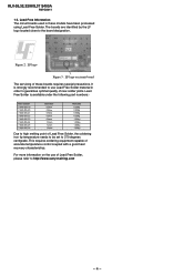
Lead Free Information The circuit boards used in order to http://www.sony-training.com - 4 - This requires soldering equipment capable of new ... in these boards requires special precautions. It is available under the following part numbers:- KLV-26,32,32/H/S,37 S400A RM-GA011 1-5. The boards are identified by the LF logo located close to 370 degrees...6mm Remarks 0.25Kg 0.50Kg 0.50Kg 0.25Kg 1.00Kg 1.00Kg 1.00Kg 1.00Kg Due to high melting point of these models have been processed using Lead Free Solder. Lead Free Solder is strongly recommended to use of Lead Free Solder, ...
Lead Free Information The circuit boards used in order to http://www.sony-training.com - 4 - This requires soldering equipment capable of new ... in these boards requires special precautions. It is available under the following part numbers:- KLV-26,32,32/H/S,37 S400A RM-GA011 1-5. The boards are identified by the LF logo located close to 370 degrees...6mm Remarks 0.25Kg 0.50Kg 0.50Kg 0.25Kg 1.00Kg 1.00Kg 1.00Kg 1.00Kg Due to high melting point of these models have been processed using Lead Free Solder. Lead Free Solder is strongly recommended to use of Lead Free Solder, ...
Revision History
Page 12
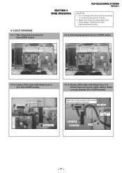
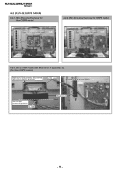
... 4 WIRE DRESSING KLV-26,32,32/H/S,37 S400A RM-GA011 CAUTION : 1. Make sure wires are kept away from sharp edges, heatsinks & other high-temperature parts. 4-1-2. Dress LVDS cable with correct direction as shown. Wire Dressing Overview for Non-CISPR model. Do not overpull the wires... during dressing --> avoid disconnection of wires. 2. 4-1.(KLV-26S400A) 4-1-1. Wire Dressing Overview for CISPR model. 4-1-3. Dress LVDS cable with Sheet Core C & Shield Tape and screw...
... 4 WIRE DRESSING KLV-26,32,32/H/S,37 S400A RM-GA011 CAUTION : 1. Make sure wires are kept away from sharp edges, heatsinks & other high-temperature parts. 4-1-2. Dress LVDS cable with correct direction as shown. Wire Dressing Overview for Non-CISPR model. Do not overpull the wires... during dressing --> avoid disconnection of wires. 2. 4-1.(KLV-26S400A) 4-1-1. Wire Dressing Overview for CISPR model. 4-1-3. Dress LVDS cable with Sheet Core C & Shield Tape and screw...
Revision History
Page 14
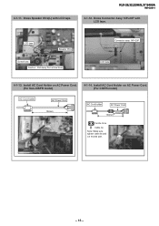
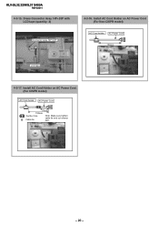
KLV-26,32,32/H/S,37 S400A RM-GA011 4-1-12. 4-1-11. Dress Speaker Wire(L) with LCD tape. Install AC Cord Holder on AC Power Cord. (For CISPR model) AC Cord holder AC Power Cord 130mm AC Cord holder AC Power Cord 70mm 130mm Ferrite Core Cable tie Note: Make sure tighten cable tie and cut excess part. - 13 - Install AC Cord Holder on AC Power Cord. (For Non-CISPR model) 4-1-14. Dress Connector Assy 14P+20P with LCD tape. LCD tape Datum Speaker Wire Screw boss Caution : Pull away from screw boss Connector assy 14P+20P Datum LCD tape 4-1-13.
KLV-26,32,32/H/S,37 S400A RM-GA011 4-1-12. 4-1-11. Dress Speaker Wire(L) with LCD tape. Install AC Cord Holder on AC Power Cord. (For CISPR model) AC Cord holder AC Power Cord 130mm AC Cord holder AC Power Cord 70mm 130mm Ferrite Core Cable tie Note: Make sure tighten cable tie and cut excess part. - 13 - Install AC Cord Holder on AC Power Cord. (For Non-CISPR model) 4-1-14. Dress Connector Assy 14P+20P with LCD tape. LCD tape Datum Speaker Wire Screw boss Caution : Pull away from screw boss Connector assy 14P+20P Datum LCD tape 4-1-13.
Revision History
Page 15
KLV-26,32,32/H/S,37 S400A RM-GA011 4-2. (KLV-32,32/H/S S400A) 4-2-1. LVDS cable Datum Datum UUsseeUULLtatpaepe location as shown. Wire Dressing Overview for Non-CISPR model 4-2-2. Dress LVDS Cable with Sheet Core C (quantity: 2). (For Non-CISPR model) Make sure LVDS connector fully inserted with correct direction as guide line UL Tape Sheet Core C Datum - 14 - Wire Dressing Overview for CISPR model 4-2-3.
KLV-26,32,32/H/S,37 S400A RM-GA011 4-2. (KLV-32,32/H/S S400A) 4-2-1. LVDS cable Datum Datum UUsseeUULLtatpaepe location as shown. Wire Dressing Overview for Non-CISPR model 4-2-2. Dress LVDS Cable with Sheet Core C (quantity: 2). (For Non-CISPR model) Make sure LVDS connector fully inserted with correct direction as guide line UL Tape Sheet Core C Datum - 14 - Wire Dressing Overview for CISPR model 4-2-3.
Revision History
Page 16
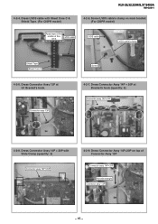
... C Datum 4-2-6. Connector assy 14P+20P 4-2-8. Dress Connector Assy 14P + 20P with Sheet Core C & Shield Tape. (For CISPR model) KLV-26,32,32/H/S,37 S400A RM-GA011 4-2-5. Dress Connector Assy 14P+20P on main bracket. (For CISPR model) Apply tape at Bracket's hook (quantity: 5). Dress Connector Assy 14P + 20P at the middle of Connector Assy...
... C Datum 4-2-6. Connector assy 14P+20P 4-2-8. Dress Connector Assy 14P + 20P with Sheet Core C & Shield Tape. (For CISPR model) KLV-26,32,32/H/S,37 S400A RM-GA011 4-2-5. Dress Connector Assy 14P+20P on main bracket. (For CISPR model) Apply tape at Bracket's hook (quantity: 5). Dress Connector Assy 14P + 20P at the middle of Connector Assy...
Revision History
Page 17
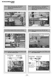
...32,32/H/S,37 S400A RM-GA011 4-2-10. Sheet Core C Speaker Wire Datum Connector assy 14P+20P Caution : Pull away from screw boss Speaker Wire Screw boss 4-2-13. Dress Speaker Wire (L) with Sheet Core C and Slide Clamp. Apply Sheet Core C on LCD Panel and dress Connector Assy 14P+20P & Speaker Wire with LCD...Datum 4-2-11. Dress Connector Assy 14P+20P & Speaker wire with LCD tape. LCD tape Datum Caution : Pull away from screw boss Screw boss 4-2-12. Install AC Cord Holder on AC Power Cord. (For CISPR model) AC Cord holder AC Power Cord 70mm 170mm Ferrite Core Cable ...
...32,32/H/S,37 S400A RM-GA011 4-2-10. Sheet Core C Speaker Wire Datum Connector assy 14P+20P Caution : Pull away from screw boss Speaker Wire Screw boss 4-2-13. Dress Speaker Wire (L) with Sheet Core C and Slide Clamp. Apply Sheet Core C on LCD Panel and dress Connector Assy 14P+20P & Speaker Wire with LCD...Datum 4-2-11. Dress Connector Assy 14P+20P & Speaker wire with LCD tape. LCD tape Datum Caution : Pull away from screw boss Screw boss 4-2-12. Install AC Cord Holder on AC Power Cord. (For CISPR model) AC Cord holder AC Power Cord 70mm 170mm Ferrite Core Cable ...
Revision History
Page 18
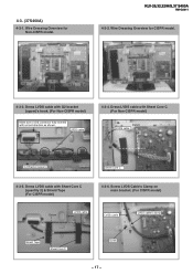
... sure LVDS connector fully inserted with Sheet Core C (quantity 2) & Shield Tape (For CISPR model) 4-3-6. Dress LVDS cable with correct direction as shown. LVDS cable 4-3-4. KLV-26,32,32/H/S,37 S400A RM-GA011 4-3-2. Dress LVDS cable with Sheet Core C. (For Non-CISPR model) Datum LVDS cable Datum G2 Bracket (upper) Sheet Core C 4-3-5. 4-3. (37S400A) 4-3-1. Screw LVDS...
... sure LVDS connector fully inserted with Sheet Core C (quantity 2) & Shield Tape (For CISPR model) 4-3-6. Dress LVDS cable with correct direction as shown. LVDS cable 4-3-4. KLV-26,32,32/H/S,37 S400A RM-GA011 4-3-2. Dress LVDS cable with Sheet Core C. (For Non-CISPR model) Datum LVDS cable Datum G2 Bracket (upper) Sheet Core C 4-3-5. 4-3. (37S400A) 4-3-1. Screw LVDS...
Revision History
Page 21
Install AC Cord Holder on AC Power Cord (For Non-CISPR model) AC Cord holder AC Power Cord 130mm LCD tape Datum 4-3-17. Dress Connector Assy 14P+20P with LCD tape (quantity: 2) Connector assy 14P+20P Datum 4-3-16. KLV-26,32,32/H/S,37 S400A RM-GA011 4-3-15. Install AC Cord Holder on AC Power Cord. (For CISPR model) AC Cord holder AC Power Cord 70mm 130mm Ferrite Core Cable tie Note: Make sure tighten cable tie and cut excess part. - 20 -
Install AC Cord Holder on AC Power Cord (For Non-CISPR model) AC Cord holder AC Power Cord 130mm LCD tape Datum 4-3-17. Dress Connector Assy 14P+20P with LCD tape (quantity: 2) Connector assy 14P+20P Datum 4-3-16. KLV-26,32,32/H/S,37 S400A RM-GA011 4-3-15. Install AC Cord Holder on AC Power Cord. (For CISPR model) AC Cord holder AC Power Cord 70mm 130mm Ferrite Core Cable tie Note: Make sure tighten cable tie and cut excess part. - 20 -
Revision History
Page 38
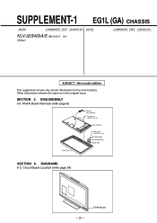
... Board Removal (refer page 8) 2 Harness with connector 1 Two screws (+BVTP2 4 X 16) 3 LCD panel 5 Two screws (+BVTP2 3 X 12) 6 HG4A board 4 One connector Guide Light Bezel assy SECTION 6. CHASSIS NO. CHASSIS NO. SECTION 3. MODEL KLV-32S400A/S RM-GA011 EA (Silver) COMMANDER DEST. DISASSEMBLY 3-3. Other information remains the same as in the original issue. Circuit...
... Board Removal (refer page 8) 2 Harness with connector 1 Two screws (+BVTP2 4 X 16) 3 LCD panel 5 Two screws (+BVTP2 3 X 12) 6 HG4A board 4 One connector Guide Light Bezel assy SECTION 6. CHASSIS NO. CHASSIS NO. SECTION 3. MODEL KLV-32S400A/S RM-GA011 EA (Silver) COMMANDER DEST. DISASSEMBLY 3-3. Other information remains the same as in the original issue. Circuit...
Revision History
Page 43
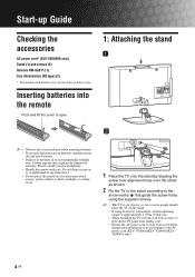
... Checking the accessories AC power cord* (KLV-40S400A only) Stand (1) and screws (3) Remote RM-GA011 (1) Size AA batteries (R6 type) (2) * For models with care. Please consult your local authority. • Handle the remote with ferrite cores, do not remove these cores. Do not drop or step on... an electric screwdriver, set the tightening torque at approximately 1.5N·m (15kgf·cm). • When installing the TV onto the wall, follow step 1 to prevent the TV panel from falling over. • Ensure the AC power cord is away from screw holes during stand installation to avoid damage...
... Checking the accessories AC power cord* (KLV-40S400A only) Stand (1) and screws (3) Remote RM-GA011 (1) Size AA batteries (R6 type) (2) * For models with care. Please consult your local authority. • Handle the remote with ferrite cores, do not remove these cores. Do not drop or step on... an electric screwdriver, set the tightening torque at approximately 1.5N·m (15kgf·cm). • When installing the TV onto the wall, follow step 1 to prevent the TV panel from falling over. • Ensure the AC power cord is away from screw holes during stand installation to avoid damage...
Revision History
Page 47
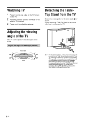
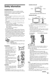
... wallmounting of your TV. Detaching the TableTop Stand from the TV Remove the screws guided by the Wall-Mount Bracket model for any reason other than to determine the strength of the TV. Sufficient expertise is required in installing this TV, especially to wall-mount the TV. For product protection and safety reasons, Sony strongly recommends that...
... wallmounting of your TV. Detaching the TableTop Stand from the TV Remove the screws guided by the Wall-Mount Bracket model for any reason other than to determine the strength of the TV. Sufficient expertise is required in installing this TV, especially to wall-mount the TV. For product protection and safety reasons, Sony strongly recommends that...
Revision History
Page 48
...TV set. • When transporting the TV set flat, install upside down and cause personal injury or damage to the TV set on the LCD panel. • When lifting or moving , pack it regularly. Operate the TV...on the cables. - Installation • The TV set should carry out wall installations. • For safety reasons, it picks up Install and use Sony accessories, including: - KLV-40S400A/KLV-37S400A...the Wall-mount bracket model. Air circulation is blocked. The core conductors may be installed near an easily accessible AC power outlet. • Place the TV set . •...
...TV set. • When transporting the TV set flat, install upside down and cause personal injury or damage to the TV set on the LCD panel. • When lifting or moving , pack it regularly. Operate the TV...on the cables. - Installation • The TV set should carry out wall installations. • For safety reasons, it picks up Install and use Sony accessories, including: - KLV-40S400A/KLV-37S400A...the Wall-mount bracket model. Air circulation is blocked. The core conductors may be installed near an easily accessible AC power outlet. • Place the TV set . •...
Revision History
Page 71
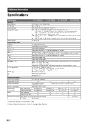
Design and specifications are approximate values. Additional Information Specifications Model name KLV-40S400A KLV-37S400A KLV-32S400A KLV-26S400A System Panel System LCD (Liquid Crystal Display) Panel TV System B/G, I, D/K, M Colour System PAL, PAL60, SECAM, NTSC4.43, NTSC3.58 Channel Coverage Sound Output B/G: VHF: E2 to E12/ UHF: E21 to E69/ CATV.../24p, 1080p (50/60 Hz), 1080i (50/60 Hz), 720p (50/60 Hz), 576p, 576i, 480p, 480i Audio: Two channel linear PCM 32, 44.1 and 48 kHz, 16, 20 and 24 bits Analogue audio input (minijack): 500 mVrms, Impedance: 47 kilohms (HDMI IN 3 only) PC...
Design and specifications are approximate values. Additional Information Specifications Model name KLV-40S400A KLV-37S400A KLV-32S400A KLV-26S400A System Panel System LCD (Liquid Crystal Display) Panel TV System B/G, I, D/K, M Colour System PAL, PAL60, SECAM, NTSC4.43, NTSC3.58 Channel Coverage Sound Output B/G: VHF: E2 to E12/ UHF: E21 to E69/ CATV.../24p, 1080p (50/60 Hz), 1080i (50/60 Hz), 720p (50/60 Hz), 576p, 576i, 480p, 480i Audio: Two channel linear PCM 32, 44.1 and 48 kHz, 16, 20 and 24 bits Analogue audio input (minijack): 500 mVrms, Impedance: 47 kilohms (HDMI IN 3 only) PC...
Revision History
Page 77
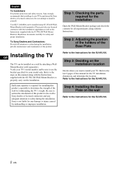
...model only. To Sony Dealers and Contractors: Provide full attention to determine the strength of the wall for withstanding the TV's weight. Sufficient expertise is not liable for installing this product, especially to safety during the installation. Sony is required for any damage or injury caused by Sony..., periodic maintenance and examination of this manual for the SU-WL100. 2 (GB) GB Installing the TV The TV can be sure to install your TV's model number and be installed using SUWL100 WallMount Bracket (sold separately). Your KLV-26S400A can be performed...
...model only. To Sony Dealers and Contractors: Provide full attention to determine the strength of the wall for withstanding the TV's weight. Sufficient expertise is not liable for installing this product, especially to safety during the installation. Sony is required for any damage or injury caused by Sony..., periodic maintenance and examination of this manual for the SU-WL100. 2 (GB) GB Installing the TV The TV can be sure to install your TV's model number and be installed using SUWL100 WallMount Bracket (sold separately). Your KLV-26S400A can be performed...
Revision History
Page 80
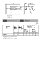
125 Screen centre point/ English Installation dimensions table AR PR Unit: mm Model Name/ Display dimensions/ Screen centre dimension/ Length for each mounting angle/ Angle (0o)/ Angle (20o)/ A B C KLV-26S400A 675 466 83 Installation dimensions may differ according to how the TV is installed. D E F G H 335 157 269 439 342
125 Screen centre point/ English Installation dimensions table AR PR Unit: mm Model Name/ Display dimensions/ Screen centre dimension/ Length for each mounting angle/ Angle (0o)/ Angle (20o)/ A B C KLV-26S400A 675 466 83 Installation dimensions may differ according to how the TV is installed. D E F G H 335 157 269 439 342
Revision History
Page 81
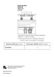
Hook location a b* Model Name KLV-26S400A * Hook position "b" cannot be used for the models in the table below. * * * Hook location a Printed in Malaysia
Hook location a b* Model Name KLV-26S400A * Hook position "b" cannot be used for the models in the table below. * * * Hook location a Printed in Malaysia


