Revision History
Page 3
... Information 4 5. White Balance Adjustment 22 5-6. Standby LED Error Display 6 6. Printed Wiring Boards 25 6-5. LCD Panel Removal 10 4. Factory Reset 22 5-5. LED Display Control 5 2-4. Circuit Board Location 24 6-3. GP Board Removal (KLV-26,32,32/H/S S400A 9 3-6. BG1, GP, HG4 Boards, Speakers, Bezel Assy and LCD Panel 28 7-2. (KLV-32,32/H/S S400A 29 7-2-1. Chassis-1 33 7-1-3. Leakage Test 3 1-4. WARNING 3 1-5. Accessing Service Menu 21...
... Information 4 5. White Balance Adjustment 22 5-6. Standby LED Error Display 6 6. Printed Wiring Boards 25 6-5. LCD Panel Removal 10 4. Factory Reset 22 5-5. LED Display Control 5 2-4. Circuit Board Location 24 6-3. GP Board Removal (KLV-26,32,32/H/S S400A 9 3-6. BG1, GP, HG4 Boards, Speakers, Bezel Assy and LCD Panel 28 7-2. (KLV-32,32/H/S S400A 29 7-2-1. Chassis-1 33 7-1-3. Leakage Test 3 1-4. WARNING 3 1-5. Accessing Service Menu 21...
Revision History
Page 4
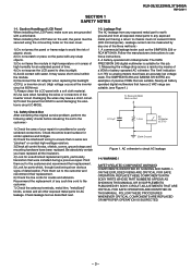
... the backlight (CCFL) or inverter circuit. (High voltage occurs at the inverter circuit at 650Vrms) 7) Always clean the LCD panel with water. Follow the manufacturers instructions to check...32,32/H/S,37 S400A RM-GA011 SECTION 1 SAFETY NOTES 1-1. Leakage current can be secured using the 4 mounting holes on the rear cover. 1) Do not press the panel or frame edge to chassis must have an accurate low voltage...entire board surface for AC leakage. WARNING ! REPLACE THESE COMPONENTS WITH SONY PARTS WHOSE PART NUMBERS APPEAR AS SHOWN IN THIS MANUAL OR IN SUPPLEMENTS PUBLISHED BY SONY. ...
... the backlight (CCFL) or inverter circuit. (High voltage occurs at the inverter circuit at 650Vrms) 7) Always clean the LCD panel with water. Follow the manufacturers instructions to check...32,32/H/S,37 S400A RM-GA011 SECTION 1 SAFETY NOTES 1-1. Leakage current can be secured using the 4 mounting holes on the rear cover. 1) Do not press the panel or frame edge to chassis must have an accurate low voltage...entire board surface for AC leakage. WARNING ! REPLACE THESE COMPONENTS WITH SONY PARTS WHOSE PART NUMBERS APPEAR AS SHOWN IN THIS MANUAL OR IN SUPPLEMENTS PUBLISHED BY SONY. ...
Revision History
Page 5
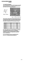
...32,32/H/S,37 S400A RM-GA011 1-5. Figure 2: LF logo Figure 3: LF logo on the use Lead Free Solder material in these boards requires special precautions. This requires soldering equipment capable of these models have been processed using Lead Free Solder. For more information on circuit board...characteristics. It is available under the following part numbers:- The boards are identified by the LF logo located close to 370 ... to the board designation. Lead Free Solder is strongly recommended to use of new solder joints. Lead Free Information The circuit boards used in...
...32,32/H/S,37 S400A RM-GA011 1-5. Figure 2: LF logo Figure 3: LF logo on the use Lead Free Solder material in these boards requires special precautions. This requires soldering equipment capable of these models have been processed using Lead Free Solder. For more information on circuit board...characteristics. It is available under the following part numbers:- The boards are identified by the LF logo located close to 370 ... to the board designation. Lead Free Solder is strongly recommended to use of new solder joints. Lead Free Information The circuit boards used in...
Revision History
Page 7
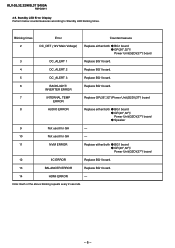
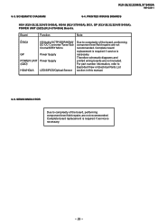
... z BG1 board z GP(26",32")/ Power Unit(G2D)(37") board 12 IIC ERROR Replace BG1 board. 13 BALANCER ERROR Replace BG1 board. 14 HDMI ERROR - Blinking times Error Countermeasure 2 DC_DET (12V Main Voltage) Replace either /both z BG1 board z GP(26",32")/ Power Unit(G2D)(37") board 3 DC_ALERT 1 Replace BG1 board. 4 DC_ALERT 2 Replace BG1 board. 5 DC_ALERT 3 Replace BG1 board. 6 BACKLIGHT/ Replace BG1 board. Standby...
... z BG1 board z GP(26",32")/ Power Unit(G2D)(37") board 12 IIC ERROR Replace BG1 board. 13 BALANCER ERROR Replace BG1 board. 14 HDMI ERROR - Blinking times Error Countermeasure 2 DC_DET (12V Main Voltage) Replace either /both z BG1 board z GP(26",32")/ Power Unit(G2D)(37") board 3 DC_ALERT 1 Replace BG1 board. 4 DC_ALERT 2 Replace BG1 board. 5 DC_ALERT 3 Replace BG1 board. 6 BACKLIGHT/ Replace BG1 board. Standby...
Revision History
Page 9
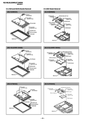
... Bezel assy 3-4. KLV-26,32,32/H/S,37 S400A RM-GA011 3-3. HG4 and HG4A Boards Removal (KLV-26S400A) 2 Harness with connector 1 Two screws (+BVTP2 4 X 16) 3 LCD panel 5 Two screws (+BVTP2 3 X 12) 6 HG4 board 4 One connector Guide Light Bezel assy (KLV-32,32/H/S S400A) 2 Harness with connector Bezel assy 5 Two screws (+BVTP2 3 X 12) 3 LCD panel 6 HG4A board 4 One connector Guide Light...
... Bezel assy 3-4. KLV-26,32,32/H/S,37 S400A RM-GA011 3-3. HG4 and HG4A Boards Removal (KLV-26S400A) 2 Harness with connector 1 Two screws (+BVTP2 4 X 16) 3 LCD panel 5 Two screws (+BVTP2 3 X 12) 6 HG4 board 4 One connector Guide Light Bezel assy (KLV-32,32/H/S S400A) 2 Harness with connector Bezel assy 5 Two screws (+BVTP2 3 X 12) 3 LCD panel 6 HG4A board 4 One connector Guide Light...
Revision History
Page 10
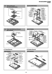
...) 1 Four screws (+PSW 3SG) 2 One connector 3 GP board G1 Bracket KLV-26,32,32/H/S,37 S400A RM-GA011 (KLV-32,32/H/S S400A) 4 One screw (+PSW M4 X 8) 5 One screw (+PSW M4 X 8) 2 Two screws (+PSW M4 X 8) Vesa Frame (Top) Assy 6 One screw (+PSW M4 X 8) 7...M4 X 8) 3 One screw (+PSW M4 X 8) Frame Spine (R) 6 Two screws (+BVTP2 4 X 16) Frame Bottom 3-8. 3-5. Power Unit (G2D) Board Removal (KLV-37S400A) 2 Six screws (+BVST 3 X 8) 3 G2 Bracket, Upper 1 Power Unit (G2D Board) Bezel Assy (KLV-37S400A) 4 Two screws 3 Two screws (+PSW M4 X 8) (+PSW M5 X 8) 5 Four screws (+PSW M4 X 8) 6 Two...
...) 1 Four screws (+PSW 3SG) 2 One connector 3 GP board G1 Bracket KLV-26,32,32/H/S,37 S400A RM-GA011 (KLV-32,32/H/S S400A) 4 One screw (+PSW M4 X 8) 5 One screw (+PSW M4 X 8) 2 Two screws (+PSW M4 X 8) Vesa Frame (Top) Assy 6 One screw (+PSW M4 X 8) 7...M4 X 8) 3 One screw (+PSW M4 X 8) Frame Spine (R) 6 Two screws (+BVTP2 4 X 16) Frame Bottom 3-8. 3-5. Power Unit (G2D) Board Removal (KLV-37S400A) 2 Six screws (+BVST 3 X 8) 3 G2 Bracket, Upper 1 Power Unit (G2D Board) Bezel Assy (KLV-37S400A) 4 Two screws 3 Two screws (+PSW M4 X 8) (+PSW M5 X 8) 5 Four screws (+PSW M4 X 8) 6 Two...
Revision History
Page 23
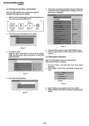
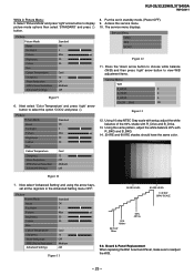
... is replaced. 1. Factory Reset Note: The TEST RESET option resets all the customer adjustable data back to Service Menu. KLV-26,32,32/H/S,37 S400A RM-GA011 5-4. While TV set on standby, press the following menu will appear on the remote commander (RM-GA011). Now return to factory defaults. 1. Press... 'up' arrow button to select OK and 'Enter' button to be adjusted when BG1 board and Panel is displayed: Service Menu Service ...
... is replaced. 1. Factory Reset Note: The TEST RESET option resets all the customer adjustable data back to Service Menu. KLV-26,32,32/H/S,37 S400A RM-GA011 5-4. While TV set on standby, press the following menu will appear on the remote commander (RM-GA011). Now return to factory defaults. 1. Press... 'up' arrow button to select OK and 'Enter' button to be adjusted when BG1 board and Panel is displayed: Service Menu Service ...
Revision History
Page 24
Access the service menu. 10. Board & Panel Replacement When replacing the BG1 board and Panel, make sure to select the option 'COOL' and press . Service Menu Status W/B Service Figure 12 11. Picture Picture Mode Reset ... press 'right' arrow button to view W/B adjustment items. Service Menu W/B R_DRIVE 0 G_DRIVE 0 B_DRIVE 0 COLOR _SAVE OK Figure 13 12. Figure 10 7. KLV-26,32,32/H/S,37 S400A RM-GA011 While in standby mode. (Power OFF). 9. Picture Picture Mode Reset Backlight Picture Brightness Colour Hue Colour Temperature Sharpness Noise Reduction MPEG...
Access the service menu. 10. Board & Panel Replacement When replacing the BG1 board and Panel, make sure to select the option 'COOL' and press . Service Menu Status W/B Service Figure 12 11. Picture Picture Mode Reset ... press 'right' arrow button to view W/B adjustment items. Service Menu W/B R_DRIVE 0 G_DRIVE 0 B_DRIVE 0 COLOR _SAVE OK Figure 13 12. Figure 10 7. KLV-26,32,32/H/S,37 S400A RM-GA011 While in standby mode. (Power OFF). 9. Picture Picture Mode Reset Backlight Picture Brightness Colour Hue Colour Temperature Sharpness Noise Reduction MPEG...

Revision History
Page 25
BLOCK DIAGRAM SECTION 6 DIAGRAMS Due to complexity of the board, performing component level field repairs are not recommended. KLV-26,32,32/H/S,37 S400A RM-GA011 6-1. Complete board replacement is required if service is necessary. 6-2. CIRCUIT BOARD LOCATION KLV-26,32,32/H/S,37 S400A BG1 Board Block Switch Panel GP Board (KLV-26,32,32/H/S S400A) Power Unit (G2D Board) (KLV-37S400A) HG4 Board (KLV-26,32,32/H/S S400A) HG4A Board (KLV-37S400A) - 24 -
BLOCK DIAGRAM SECTION 6 DIAGRAMS Due to complexity of the board, performing component level field repairs are not recommended. KLV-26,32,32/H/S,37 S400A RM-GA011 6-1. Complete board replacement is required if service is necessary. 6-2. CIRCUIT BOARD LOCATION KLV-26,32,32/H/S,37 S400A BG1 Board Block Switch Panel GP Board (KLV-26,32,32/H/S S400A) Power Unit (G2D Board) (KLV-37S400A) HG4 Board (KLV-26,32,32/H/S S400A) HG4A Board (KLV-37S400A) - 24 -
Revision History
Page 26
... if service is necessary. Complete board replacement is required if service is necessary. - 25 - SCHEMATIC DIAGRAM 6-4. For part number information, refer to complexity of the board, performing component level field repairs are not included. PRINTED WIRING BOARDS HG4 (KLV-26,32,32/H/S S400A), HG4A (KLV-37S400A), BG1, GP (KLV-26,32,32/H/S S400A), POWER UNIT (G2D) (KLV...
... if service is necessary. Complete board replacement is required if service is necessary. - 25 - SCHEMATIC DIAGRAM 6-4. For part number information, refer to complexity of the board, performing component level field repairs are not included. PRINTED WIRING BOARDS HG4 (KLV-26,32,32/H/S S400A), HG4A (KLV-37S400A), BG1, GP (KLV-26,32,32/H/S S400A), POWER UNIT (G2D) (KLV...
Revision History
Page 29
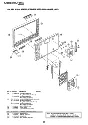
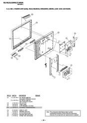
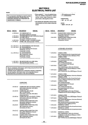
...GUIDE, LIGHT 105 1-826-648-21 LOUD SPEAKER (4.2 X 15CM) 106 ! 1-802-613-11 LCD PANEL (26INCH WXGA TFT) 107 X-2189-890-01 BEZEL(26) ASSY 108 4-103-599-21 EMBLEM, SONY NO.7 109 * A-1527-469-A HG4 MOUNT 110 X-2318-678-1 BRACKET, SIDE JACK ASSY h... Note: The components identified by mark contain confidential information. Strictly follow the instructions whenever the components are repaired and /or replaced. - 28 - KLV-26,32,32/H/S,37 S400A RM-GA011 7-1-3. BG1, GP, HG4 BOARDS, SPEAKERS, BEZEL ASSY AND LCD...
...GUIDE, LIGHT 105 1-826-648-21 LOUD SPEAKER (4.2 X 15CM) 106 ! 1-802-613-11 LCD PANEL (26INCH WXGA TFT) 107 X-2189-890-01 BEZEL(26) ASSY 108 4-103-599-21 EMBLEM, SONY NO.7 109 * A-1527-469-A HG4 MOUNT 110 X-2318-678-1 BRACKET, SIDE JACK ASSY h... Note: The components identified by mark contain confidential information. Strictly follow the instructions whenever the components are repaired and /or replaced. - 28 - KLV-26,32,32/H/S,37 S400A RM-GA011 7-1-3. BG1, GP, HG4 BOARDS, SPEAKERS, BEZEL ASSY AND LCD...
Revision History
Page 32
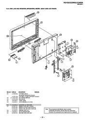
...21 LOUD SPEAKER (4.2 X 15CM) 106 ! 1-802-653-12 LCD PANEL (32 WXGA TFT) 107 X-2189-523-1 BEZEL(32) ASSY (KLV-32S400A) X-2318-468-1 BEZEL(32)(S) ASSY (KLV-32S400A/S) X-2318-464-1 BEZEL(32)(H) ASSY (KLV-32S400A/H) 108 4-103-642-21 EMBLEM, SONY NO.7 109 * 1-480-889-11 BLOCK SWITCH PANEL 110 X-...2318-678-1 BRACKET, SIDE JACK ASSY Note: The components identified by mark contain confidential information. NO. BG1, GP, HG4 BOARDS, SPEAKERS, BEZEL ASSY AND LCD PANEL 109 KLV-26,32,32/H/S,37 S400A RM-GA011 107...
...21 LOUD SPEAKER (4.2 X 15CM) 106 ! 1-802-653-12 LCD PANEL (32 WXGA TFT) 107 X-2189-523-1 BEZEL(32) ASSY (KLV-32S400A) X-2318-468-1 BEZEL(32)(S) ASSY (KLV-32S400A/S) X-2318-464-1 BEZEL(32)(H) ASSY (KLV-32S400A/H) 108 4-103-642-21 EMBLEM, SONY NO.7 109 * 1-480-889-11 BLOCK SWITCH PANEL 110 X-...2318-678-1 BRACKET, SIDE JACK ASSY Note: The components identified by mark contain confidential information. NO. BG1, GP, HG4 BOARDS, SPEAKERS, BEZEL ASSY AND LCD PANEL 109 KLV-26,32,32/H/S,37 S400A RM-GA011 107...
Revision History
Page 35
...408-01 GUIDE, LIGHT 104 1-826-648-21 LOUD SPEAKER (4.2 X 15CM) 105 ! 1-802-622-11 LCD PANEL (37INCH WXGA TFT) 106 X-2190-008-1 BEZEL(37) ASSY 107 4-103-642-21 EMBLEM, SONY NO.7 108 * 1-480-889-11 BLOCK SWITCH PANEL 109 * X-2318-678-1 BRACKET, SIDE JACK ASSY 110... * 1-474-095-12 POWER, UNIT (G2D BOARD) Note: The components identified by mark contain confidential information. NO. Strictly follow the instructions whenever the components are repaired and /or replaced. - 34 - KLV-26,32,32/H/S,37 S400A RM-GA011 7-3-3.
...408-01 GUIDE, LIGHT 104 1-826-648-21 LOUD SPEAKER (4.2 X 15CM) 105 ! 1-802-622-11 LCD PANEL (37INCH WXGA TFT) 106 X-2190-008-1 BEZEL(37) ASSY 107 4-103-642-21 EMBLEM, SONY NO.7 108 * 1-480-889-11 BLOCK SWITCH PANEL 109 * X-2318-678-1 BRACKET, SIDE JACK ASSY 110... * 1-474-095-12 POWER, UNIT (G2D BOARD) Note: The components identified by mark contain confidential information. NO. Strictly follow the instructions whenever the components are repaired and /or replaced. - 34 - KLV-26,32,32/H/S,37 S400A RM-GA011 7-3-3.
Revision History
Page 36
... Zealand)) GP COMPLETE KIT (26) (KLV-26S400A(New Zealand)) GP COMPL KIT (32) (Except KLV-32S400A(New Zealand)) GP COMPL (32) (KLV-32S400A(New Zealand)) POWER, UNIT (G2D board) (KLV-37S400A REF NO. DESCRIPTION The components identified by mark contain confidential information. Complete... 32S400A(New Zealand), 37S400A(New Zealand * A-1527-469-A HG4 MOUNT (KLV-26,32,32/H/S S400A) A-1548-456-A HG4A MOUNT (KLV-37S400A Due to the Exploded View or Electrical Parts List section of the board, performing component level field repairs are in ohms • F : nonflammable CAPACITORS •...
... Zealand)) GP COMPLETE KIT (26) (KLV-26S400A(New Zealand)) GP COMPL KIT (32) (Except KLV-32S400A(New Zealand)) GP COMPL (32) (KLV-32S400A(New Zealand)) POWER, UNIT (G2D board) (KLV-37S400A REF NO. DESCRIPTION The components identified by mark contain confidential information. Complete... 32S400A(New Zealand), 37S400A(New Zealand * A-1527-469-A HG4 MOUNT (KLV-26,32,32/H/S S400A) A-1548-456-A HG4A MOUNT (KLV-37S400A Due to the Exploded View or Electrical Parts List section of the board, performing component level field repairs are in ohms • F : nonflammable CAPACITORS •...
Revision History
Page 38
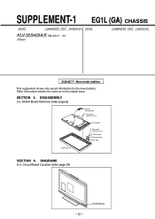
... variant information for the new model(s). Circuit Board Location (refer page 24) HG4A Board - 37 - Other information remains the same as in the original issue. DIAGRAMS 6-2. MODEL KLV-32S400A/S RM-GA011 EA (Silver) COMMANDER DEST. HG4A Board Removal (refer page 8) 2 Harness with connector 1 Two screws (+BVTP2 4 X 16) 3 LCD panel 5 Two screws (+BVTP2 3 X 12) 6 HG4A...
... variant information for the new model(s). Circuit Board Location (refer page 24) HG4A Board - 37 - Other information remains the same as in the original issue. DIAGRAMS 6-2. MODEL KLV-32S400A/S RM-GA011 EA (Silver) COMMANDER DEST. HG4A Board Removal (refer page 8) 2 Harness with connector 1 Two screws (+BVTP2 4 X 16) 3 LCD panel 5 Two screws (+BVTP2 3 X 12) 6 HG4A...
Revision History
Page 39
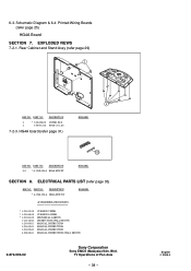
...7-2-1. PART NO. DESCRIPTION 2 * 3-106-086-01 COVER, ECS 4 3-700-532-01 FOOT (15 x 20) 7-2-3. HG4A board (refer page 31) REMARK 103 REF NO. PART NO. ELECTRICAL PARTS LIST (refer page 35) REF NO. English 2008...) MANUAL, INSTRUCTION MANUAL, INSTRUCTION MANUAL, INSTRUCTION MANUAL, INSTRUCTION (WALL MOUNT) 9-872-993-02 Sony Corporation Sony EMCS (Malaysia) Sdn. Bhd. DESCRIPTION 103 * A-1548-456-A HG4A MOUNT REMARK SECTION 8. Printed Wiring Boards (refer page 25) HG4A Board SECTION 7. TV Operations of Pan Asia - 38 - PART NO. Schematic Diagram & 6-4.
...7-2-1. PART NO. DESCRIPTION 2 * 3-106-086-01 COVER, ECS 4 3-700-532-01 FOOT (15 x 20) 7-2-3. HG4A board (refer page 31) REMARK 103 REF NO. PART NO. ELECTRICAL PARTS LIST (refer page 35) REF NO. English 2008...) MANUAL, INSTRUCTION MANUAL, INSTRUCTION MANUAL, INSTRUCTION MANUAL, INSTRUCTION (WALL MOUNT) 9-872-993-02 Sony Corporation Sony EMCS (Malaysia) Sdn. Bhd. DESCRIPTION 103 * A-1548-456-A HG4A MOUNT REMARK SECTION 8. Printed Wiring Boards (refer page 25) HG4A Board SECTION 7. TV Operations of Pan Asia - 38 - PART NO. Schematic Diagram & 6-4.

